
Module Two
Virginia Driver Responsibilities:
Preparing to Operate a Vehicle
•
Driver Preparation Procedures
•
Identifying Vehicle Control Devices
•
Operating Vehicle Control Devices
•
Vehicle Balance Considerations
•
Standard Vehicle Reference Points
Virginia Department of Education
in cooperation with the
Virginia Department of Motor Vehicles
Curriculum Scope and Sequence Modules
for Driver Education in Virginia

Table of Contents
Standards of Learning Addressed in This Module ..................................................... 1
Introduction ................................................................................................................... 2
Topic 1—Driver Preparation Procedures .................................................................... 3
Lesson 1 ......................................................................................................................... 4
Lesson 2 ......................................................................................................................... 6
Lesson 3 ......................................................................................................................... 8
Lesson 4 ....................................................................................................................... 12
Topic 2—Identifying Vehicle Control Devices ........................................................... 13
Lesson 1 ....................................................................................................................... 14
Lesson 2 ....................................................................................................................... 16
Topic 3—Operating Vehicle Control Devices ............................................................
19
Lesson 1 ....................................................................................................................... 20
Lesson 2 ....................................................................................................................... 24
Topic 4—Vehicle Balance Considerations ................................................................ 27
Lesson 1 ....................................................................................................................... 28
Lesson 2 ....................................................................................................................... 32
Topic 5—Standard Vehicle Reference Points ........................................................... 37
Lesson 1 ....................................................................................................................... 38
Lesson 2 ....................................................................................................................... 48
Lesson 3 ....................................................................................................................... 54
Worksheets .................................................................................................................. 59
Simulation .................................................................................................................... 70
Assessment ................................................................................................................. 71

Standards of Learning Addressed In This Module
Module Two—August, 2001 Page 1
DE.2 The student will demonstrate an understanding of basic vehicle operating procedures.
Key concepts/skills include
a) pre-driving procedures;
b) starting procedures (automatic and manual transmissions);
c) vehicle information, warning, and control devices;
d) vehicle securing procedures.
DE.3 The student will recognize the effects of momentum, gravity, and inertia on vehicle
control and balance, and the relationship between kinetic energy and force of impact.
Key concepts/skills include
a) seating and hand position;
b) steering, braking, and acceleration;
c) compensating for shifts in vehicle load (from side to side, front to rear, and rear to
front) that affect vehicle performance;
d) types of collisions — head-on, near-frontal, broadside, rear-end, rollover, sideswipe.
DE.4 The student will demonstrate the ability to manage visibility, time, and space to avoid
conflicts and reduce driving risks. Key concepts/skills include
a) synthesizing information visually from the driving environment, using a space-
management
process;
b) applying following-interval concepts;
c) selecting gap and judging distance;
d) estimating passing-time and space needs.
DE.7 The student will demonstrate the ability to communicate presence and intentions with
other highway transportation users. Key concepts/skills include
a) vehicle position and driver action;
b) vehicle communication devices.
DE.15 The student will identify and evaluate emergency response strategies to reduce the
severity of or avoid a collision in high-risk driving situations. Key concepts/skills include
a) evasive maneuvers, using brake and steering combinations;
b) off-road recovery;
c) front and rear traction control.
DE.18 The student will analyze how preventive maintenance reduces the possibility of vehicle
failures and recognize the warning signs that indicate the need for maintenance, repair,
or replacement. Key concepts/skills include
a) vehicle warning devices;
b) lights and signals;
c) steering and suspension systems;
d) tires and braking systems;
e) fuel and ignition electronics.

Module Two Introduction
Module Two—Virginia Driver Responsibilities: Preparing to Operate a Vehicle
The student will recognize the necessity of making routine vehicle checks and adjustments prior to and after
entering the vehicle; appropriately identify and respond to alert symbols, warning symbols, vehicle control
devices, and safety devices; understand and control vehicle balance and vehicle operating space; and
appropriately apply the techniques of vehicle reference points to establish roadway position and vehicle
placement.
Topic 1—Driver Preparation Procedures
The student will utilize basic procedures and readiness techniques to enter, start, and secure the vehicle, and
perform basic vehicle maintenance checks.
Topic 2—Identifying Vehicle Control Devices
The student will recognize and understand the function and operation of each vehicular alert or warning
symbol, control device, information device, and comfort system.
Topic 3—Operating Vehicle Control Devices
The student will demonstrate proper steering, braking, and acceleration techniques, and be able to operate
the vehicular systems and devices while seated in the driver’s seat.
Topic 4—Vehicle Balance Considerations
The student will recognize the effects of steering, braking, and acceleration on the balance of a vehicle, and
will demonstrate vehicular control utilizing vehicle balance techniques.
Topic 5—Standard Vehicle Reference Points
The student will utilize standard vehicle reference points to determine and execute lane placement, stopping
position, and turning maneuvers.
Classroom Instruction
Topic 1 — Driver Preparation Procedures
Topic 2 — Identifying Vehicle Control Devices
Topic 3 — Operating Vehicle Control Devices
Topic 4 — Vehicle Balance Considerations
Topic 5 — Standard Vehicle Reference Points
Recommended Minutes
20
30
50
25
30
Supplement—Parent Participation Activities 55
In-Car Instruction (Option 1)
Behind-the-Wheel Instruction/Break
Observation
Laboratory Multiphase (Option 2)
Behind-the-Wheel Instruction/Break
Observation
Simulation
50
50
40
80
120
Parental Involvement 60
Minimum Time Frames
Module Two–3 Hours
Module Two—August, 2001 Page 2

Instructor Activities
Time Frame
Module Two
Topic 1—Driver Preparation Procedures
Review Module Two, Topic 1 Lesson Plans Prior to Lesson
Show Transparencies
T-2.1 “Pre-Drive Tasks”
T-2.2 “Pre-Drive Tasks”
T-2.3 “Pre-Drive Tasks”
T-2.4 “Under the Hood Checks”
T-2.5 “Driver Readiness Tasks”
T-2.6 “Driver Readiness Tasks”
T-2.7 “Starting Tasks”
T-2.8 “Starting Tasks”
T-2.9 “Securing Tasks”
T-2.10 “Securing Tasks”
Distribute and Review Student Worksheets
W-2.1 “Driver Preparations”
W-2.2 “Under the Hood Checks”
Review Module Assessments Prior to Lesson
MA-2.1 “Module Two Assessment”
Additional Resources (Media and/or Text)
Video: “Teaching Your Teens To Drive.” (AAA)
“Owners Manual” for the driver education vehicle
“Drive Right”
“Empower Yourself with Zone Control Driving”
“Handbook Plus”
“How to Drive”
“License To Drive”
“Responsible Driving”
20 minutes
(2-3 minutes)
(2-3 minutes)
(2-3 minutes)
(2-5 minutes)
(2-3 minutes)
(2-3 minutes)
(2-3 minutes)
(2-3 minutes)
(2-3 minutes)
(1-2 minutes)
10 minutes
20 Minutes Instructional Time
Prerequisites: Qualifies for Valid Learner’s Permit
Module Two—August, 2001 Page 3

Activities & Resources
T-2.2 Pre-Drive Tasks
Knowledge and Skills
The student is expected to describe and demonstrate pre-drive tasks.
Distribute Worksheet W-2.1 “Driver Preparations” to students
for completion during this section.
Topic: 1 Lesson: 1
Driver Preparation Procedures
Show Transparencies T-2.1, T-2.2, and T-2.3 “Pre-Drive
Tasks” to discuss pre-drive checks around the vehicle.
•
Check around outside of vehicle.
•
Check for small children and pets.
• Store valuables in the trunk.
•
Approach driver’s door from front.
•
Approach door from rear in parking lot.
• Check vehicle and traffic flow.
• Unlock door and enter quickly.
T-2.1 Pre-Drive Tasks
T-2.3 Pre-Drive Tasks
Module Two—August, 2001 Page 4

Topic: 1 Lesson: 1
...continued
Support Information
Driver Preparation
The driver preparation section involves all the tasks that lead up to putting the car in motion and securing
the vehicle. The topics will review pre-drive, driver readiness, starting, and securing tasks. The novice
driver will be introduced to the preventive maintenance responsibilities associated with using a vehicle.
The driver will review the meaning of vehicle controls and their locations. Appropriate uses of each are
described in this support information. The module concludes with a discussion of targeting skills and the
relationship of the vehicle operating space to standard vehicle reference points. A mirroring technique is
introduced that will eliminate mirror blind spots and reduce night glare in the side view mirrors. Module
Two, Topic 1 starts with pre-drive tasks and concludes with developing standard reference points. This
topic prepares the novice driver for the first in-car lesson.
Reviewing Pre-Drive Inspection
The driver will become familiar with the specific tasks related to approaching the vehicle in a safe
manner. The tasks are not listed in order of importance. The student will develop a preferred sequence
or procedure on Worksheet W-2.1 with the guidance of the instructor.
On Approach to Vehicle
•
Check outside of vehicle.
• Check for small children and pets.
•
Check for obvious fluid leakage. Identify the source of any leaking fluids (coolant, air conditioner
condensation, brake, motor oil, transmission fluid).
• Check for tire inflation, position, and damage.
• Check for obvious physical damage to body or glass.
•
Approach driver’s door from front when parked at curb.
• Approach from rear when parked in a parking lot.
On Arrival to Vehicle
•
Store all valuables in trunk or secure on floor of vehicle.
• Look into vehicle and check traffic flow.
• Unlock doors to enter vehicle.
•
Enter vehicle with key in hand.
• Place key at appropriate location (dash/console). Storage of key on dashboard will prevent start-up
before pre-start procedures are completed.
•
Sit directly behind the steering wheel and allow for comfortable access to brake pedal and accelerator,
which is the greatest distance from the driver, while keeping heel of foot on floorboard.
• Adjust head restraints. To minimize neck injury, level head restraint directly across from top of ear.
Recognize that a lowered head restraint may cause injury in a crash and encourages whiplash.
•
Fasten seat and shoulder restraints. Prevent yourself from being thrown about or out of the vehicle by
adjusting seat and shoulder restraints snugly across hips and chest.
• Adjust mirrors to gain maximum field of vision and sight distance from rear and side view mirrors, and to
reduce or eliminate mirror blind spot.
•
Set or check parking brake.
• Lock the handle device. Locked doors are not “dead locked,” and may fly open in a crash.
“Teaching Your Teens To Drive” (AAA) provides a video, student
guide, and parent guide that have three lesson segments
devoted to driver preparation, starting, and moving the vehicle.
This resource adds to the information presented in this segment.
Module Two—August, 2001 Page 5

Knowledge and Skills
The student is expected to summarize basic vehicle maintenance checks outlined in the owner’s
manual.
Activities & Resources
Show Transparency T-2.4 “Under the Hood Checks” to discuss
basic maintenance self-checks under the hood.
Distribute Worksheet W-2.2 “Under the Hood Checks” to
students for completion during this section.
Each driver should have an idea of his/her responsibility for
vehicle maintenance. The owner’s manual of any vehicle will
provide information about periodic maintenance. Emphasize
the need for periodic maintenance to be completed by qualified
service personnel. Many vehicles can be driven 100,000 miles
before the first scheduled engine tune-up. For instance, Ford
and General Motor Companies’ maintenance schedules for
most of the 1999 passenger cars, minivans, light trucks, sport
utilities, vans, and 4x4s extend over 150,000 miles. However,
it is important to remember that certain items require service
on a more frequent schedule.
Provide students with some background information about
basic maintenance requirements. The vehicle owner’s manual
is the recommended resource for maintenance information.
Ask the students to bring copies of family vehicle owner’s
manual to class for comparison of information provided.
Topic: 1 Lesson: 2
Driver Preparation Procedures
T-2.4
Under the Hood Checks
Module Two—August, 2001 Page 6

Topic: 1 Lesson: 2
Support Information
Weekly Self-Checks—Tire Pressure, Tire Wear, and Damage
• Maximum pressure listed on tire side-wall
•
Vehicle manufacturer’s pressure recommendation for smooth ride
•
Tire tread wear, damage, or bars showing
• Cuffing (uneven wear on inside or outside tread areas)
•
Bald spots, bald center, or worn side treads
•
Cuts, stones, metal fragments, or other damage
Weekly Self-Checks—Vehicle Safety, Communication Devices, and Accessories
• Headlights, tail lights, and turn signals
•
Emergency lights and markers
•
Emergency kit
• Windshield wiper blades, operation, and washer fluid
• Heating, ventilation, and air conditioner systems (HVAC)
•
Safety warning lamps (brake, ABS, air bag, safety belt) for operation
Regular (1-2 Months) Self-Checks
• Function of all interior and exterior lights
•
Engine oil level, brake fluid level, and engine coolant level
•
Lap/shoulder belts and seat latches for wear and function
Self-Check (Twice Per Year)
• Air pressure in spare tire
•
Power steering fluid level
•
Parking brake for proper operation
• Hinges, latches, door weather strips, and outside locks (check and lubricate)
• Body and door drain holes (check and clean)
•
Cooling system coolant strength
• Battery connections (clean if necessary)
• Transmission fluid level
Professional Service Every 3,000-5,000 Miles
•
Oil change/filter replacement
• Tire rotation/balance
Professional Service Every 15,000 Miles
•
Automatic transmission fluid level
•
Brake pads/shoes/rotors/drums, brake lines, hoses, and parking brake system
• Engine cooling system
• Steering linkage, suspension and, if equipped, drive shaft and ball joints
•
Cabin air filter replacement, if equipped
Professional Service Every 30,000 Miles
• Exhaust system and heat shield
• Engine air filter and fuel filter replacement
•
Accessory drive belts
• Automatic transmission/transaxle service, if equipped
Check owner’s manual for vehicle maintenance recommendations.
Module Two—August, 2001 Page 7

Show Transparencies T-2.5 and T-2.6 “Driver Readiness
Tasks” to discuss driver seating position, restraints, and mirror
adjustments made prior to starting a motor vehicle. Encourage
students to list the procedures on Worksheet W-2.1.
Knowledge and Skills
The student is expected to:
• describe and demonstrate driver readiness tasks.
•
describe and demonstrate vehicle starting tasks.
Activities & Resources
Show Transparency T-2.7 “Starting Tasks” to discuss driver
tasks necessary to start a motor vehicle. Encourage students to
list the procedures on Worksheet W-2.1.
Topic: 1 Lesson: 3
Driver Preparation Procedures
T-2.5 Driver Readiness Tasks
T-2.6 Driver Readiness Tasks
T-2.7 Starting Tasks
Module Two—August, 2001 Page 8

Topic: 1 Lesson: 3
...continued
Support Information
Driver Readiness Tasks (Recommended for Use In-Car)
Security Needs
•
Entry checks
• Locking doors
Seating Position
•
Feet position
• Arm position
•
Hand position
•
Visual needs (chin above steering wheel)
Active Restraints
•
Safety belts
•
Head restraints
Mirror Settings
•
Rear mirror setting position
• Side mirror setting to reduce mirror blind zone and glare elimination (BGE)
Starting Tasks (Recommended for Use In-Car)
• Check parking brake.
•
Place foot on brake.
• Put key in ignition.
• Place shift selector in “Park” or “Neutral.”
•
Check for fuel injection or automatic choke.
•
Turn key to “on” position.
• Check alert lights and gauges.
•
Turn key to start engine.
•
Adjust heating, ventilation, and air conditioning (HVAC).
• Set accessories (headlights or daylight running lights are recommended).
• Check for warning lights and gauges.
Show Transparency T-2.8 “Starting Tasks” to continue
discussing driver tasks needed to start a motor vehicle, and
guide students in listing the procedures on Worksheet W-2.1.
It is recommended that the owner’s manual for the driver
education vehicle be used as supplemental text in this session.
The owner’s manual often has starting and securing
procedures as an integral part of the ‘getting to know your
vehicle’ section.
T-2.8 Starting Tasks
Module Two—August, 2001 Page 9

Topic: 1 Lesson: 3
...continued
Starting Procedure Information and Sample Questions
Parking Brake
If parking brake is firmly set, will the vehicle move? What wheel(s) does this brake control? How do you
release the parking brake? Should parking brakes be used year-round?
Foot on Service Brake
Prevents vehicle from moving before you are ready. Keeps driver from using the accelerator pedal when
starting the engine.
Key in Ignition
Which key enters the ignition? Which side of key is up? What is the other key for? How do keys differ with
various makes of vehicles?
Gear Selection (Park/Neutral)
Most automatic transmission vehicles will not start in any gear except park or neutral. Where are these
gears located on the selector indicator? How does park differ from neutral? When would neutral be used
instead of park?
Fuel Injection/Choke
Most new vehicles are fuel-injected. Owner's Manual or EFI markings indicate fuel injection. The choke on
older vehicles controls the fuel-air mixture entering the carburetor to facilitate burn.
Ignition to Start
A key is necessary to unlock steering control and start vehicle. Note position of start switch and watch
engine information light for indication that the engine is on. Be careful not to hold key longer than a few
seconds. The owner’s manual provides guidelines for timing of start.
Gauge Check
Gauges provide certain information concerning the mechanical condition of the vehicle and warn of any
unusual vehicle problems.
Accessories Needed
Turn on or adjust any needed accessories (i.e., ventilation system, daylight running lights, night headlights,
wipers, defrosters, radio, or other devices). Daylight running lights are becoming standard equipment on
General Motors vehicles. Studies indicate that crashes are reduced when vehicles are more visible.
(Headlight use on driver education vehicles is recommended due to the school divisions’ responsibility for
providing a higher level of care for their students' safety.)
Module Two—August, 2001 Page 10
Module Two—August, 2001 Page 11
Notes

Activities & Resources
Knowledge and Skills
The student is expected to describe and demonstrate vehicle securing tasks.
Show Transparencies T-2.9 and T-2.10 “Securing Tasks” to
discuss driver tasks needed to secure a motor vehicle, and
guide students in listing the procedures on Worksheet W-
2.1.
•
Stop in a legal, secure parking space.
• Set parking brake.
• Place shift selector in (P)ark.
•
Turn off any accessories used.
•
Turn ignition switch to “off.”
• “Lock” ignition and remove key.
• Remove occupant restraints.
•
Check traffic prior to exiting vehicle.
• Secure doors and windows.
Topic: 1 Lesson: 4
Driver Preparation Procedures
T-2.9 Securing Tasks
Teaching Your Teens To Drive” (AAA) provides a video,
student guide, and parent guide that have three lesson
segments devoted to driver preparation, starting, and moving
the vehicle. This resource adds to the information presented
in this segment.
T-2.10 Securing Tasks
Module Two—August, 2001 Page 12

Instructor Activities
Time Frame
Module Two
Topic 2—Identifying Vehicle Control Devices
30 minutes
(2-5 minutes)
(2-5 minutes)
(2-5 minutes)
(2-5 minutes)
(2-5 minutes)
(2-5 minutes)
(2-5 minutes)
10-15 minutes
30 Minutes Instructional Time
Prerequisites: Qualifies for Virginia Learner’s Permit
Review Module Two, Topic 2 Lesson Plans Prior to Lesson
Show Transparencies
T-2.11 "Alert/Warning Symbols and Controls”
T-2.12 "Alert/Warning Symbols and Controls”
T-2.13 "Control, Information, Comfort, and Safety Devices”
T-2.14 "Control, Information, Comfort, and Safety Devices”
T-2.15 "Control, Information, Comfort, and Safety Devices”
T-2.16 "Control, Information, Comfort, and Safety Devices”
T-2.17 "Control, Information, Comfort, and Safety Devices”
Distribute and Review Student Worksheets
W-2.3 "Control and Information Devices”
W-2.4 "Control, Information, Comfort, and Safety Devices”
W-2.5 "Family Vehicle Instrument Panel”
Review Module Assessments Prior to Lesson
W-2.3 "Control and Information Devices”
W-2.4 "Control, Information, Comfort, and Safety Devices”
W-2.5 "Family Vehicle Instrument Panel”
W-2.6 "Family Vehicle Equipment”
MA-2.1 “ Module Two Assessment”
Additional Resources (Media and/or Text)
Video: “Teaching Your Teens To Drive.” (AAA)
“Owner’s Manual” for the driver education vehicle
“Drive Right”
“Empower Yourself with Zone Control Driving”
“Handbook Plus”
“How to Drive”
“License To Drive”
“Responsible Driving”
Module Two—August, 2001 Page 13

Show Transparency T-2.11 “Alert/ Warning Symbols and
Controls” to discuss the alert and warning symbols found in
motor vehicles. Provide information on vehicular control,
convenience, safety, and communication devices, with
attention to their safe and proper use.
Knowledge and Skills
The student is expected to recognize each vehicular alert or warning symbol and explain the symbol’s
function and operation.
Activities & Resources
Show Transparency T-2.12 “Alert/Warning Symbols and
Controls” to continue discussing the alert and warning
symbols.
Use Worksheet W-2.3 “Control and Information Devices”
during classroom discussion to illustrate the various
operational controls.
Topic: 2 Lesson: 1
Identifying Vehicle Control Devices
T-2.11 Alert/Warning Symbols
and Controls
T-2.12 Alert/Warning Symbols
and Controls
Provide W-2.5 “Family Vehicle Instrument Panel” for use as a
parent involvement activity. Use the vehicle owner’s manual to
compare the control and information devices and symbols on
the dashboard with the ones illustrated on the worksheet.
Note: W-2.5 may be used as a Topic 3 assessment tool, which
gives students a longer time period to complete the exercise.
Module Two—August, 2001 Page 14

Topic: 2 Lesson: 1
...continued
Support Information
Purpose of Lesson
• Assist students in recognizing the symbols used to identify the operation, safety, communication, and
control devices found in motor vehicles.
•
Assist students in correctly responding to and operating the various safety, communication, and control
devices found in motor vehicles.
Transparency Answers
A. Air Bag On/Off Switch B. Air Bag Activation
C. Antilock Brake System Activation D. Theft Deterrent System Activation
E. 12 Volt Extension Outlet F. Battery Warning Light
G. Brake Warning Light H. Safety Alert Symbol
I. Vent and Air Flow Control J. Door Locks
K. Low Oil Pressure Warning Light L. Temperature Indicator
M. Seat Belt Reminder N. Fog Lamps
O. Drive Wheel Selector P. Fuel Indicator
Q. Fuse / Fuse Box R. Emergency Flashers
S. Turn Signal/Wipers Stalk T. Headlights/High Beam Indicator
U. Hood Release V. Horn
W. Fan Speed Indicator X. Interior Light Adjustment
Y. Lighter Indicator Z. Exterior Lights
AA. Overdrive On/Off switch BB. Parking Lamp Indicator
CC. Adjust Left/Right Side Mirror DD. Power Window Controls
EE. Rear Defroster Indicator FF. Cruise Control Device
GG. Steering Wheel Height Adjustment HH. Trunk Release
II. Left/Right Signal Indicator JJ. Front Windshield Defroster
KK. Windshield Washer LL. Windshield Wipers
MM. Electronic Traction System Control
“Teaching Your Teens To Drive” (AAA) provides a video, student
guide, and parent guide that have three lesson segments
devoted to driver preparation, starting, and moving the vehicle.
This resource adds to the information presented in this segment.
Module Two—August, 2001 Page 15

Knowledge and Skills
The student is expected to identify the location and function of the various control, information, comfort,
and safety devices.
Activities & Resources
Show Transparencies T-2.13, T-2.14, T-2.15, T-2.16, and T-2.17
“Control, Information, Comfort, and Safety Devices” to identify
the location and function of the various control, information,
comfort, and safety devices. The switches, dials, gauges, and
levers confronted by a driver are identified.
Topic: 2 Lesson: 2
Identifying Vehicle Control Devices
T-2.13 Control, Information,
Comfort, and Safety Devices
T-2.14 Control, Information,
Comfort, and Safety Devices
T-2.15 Control, Information,
Comfort, and Safety Devices
Module Two—August, 2001 Page 16
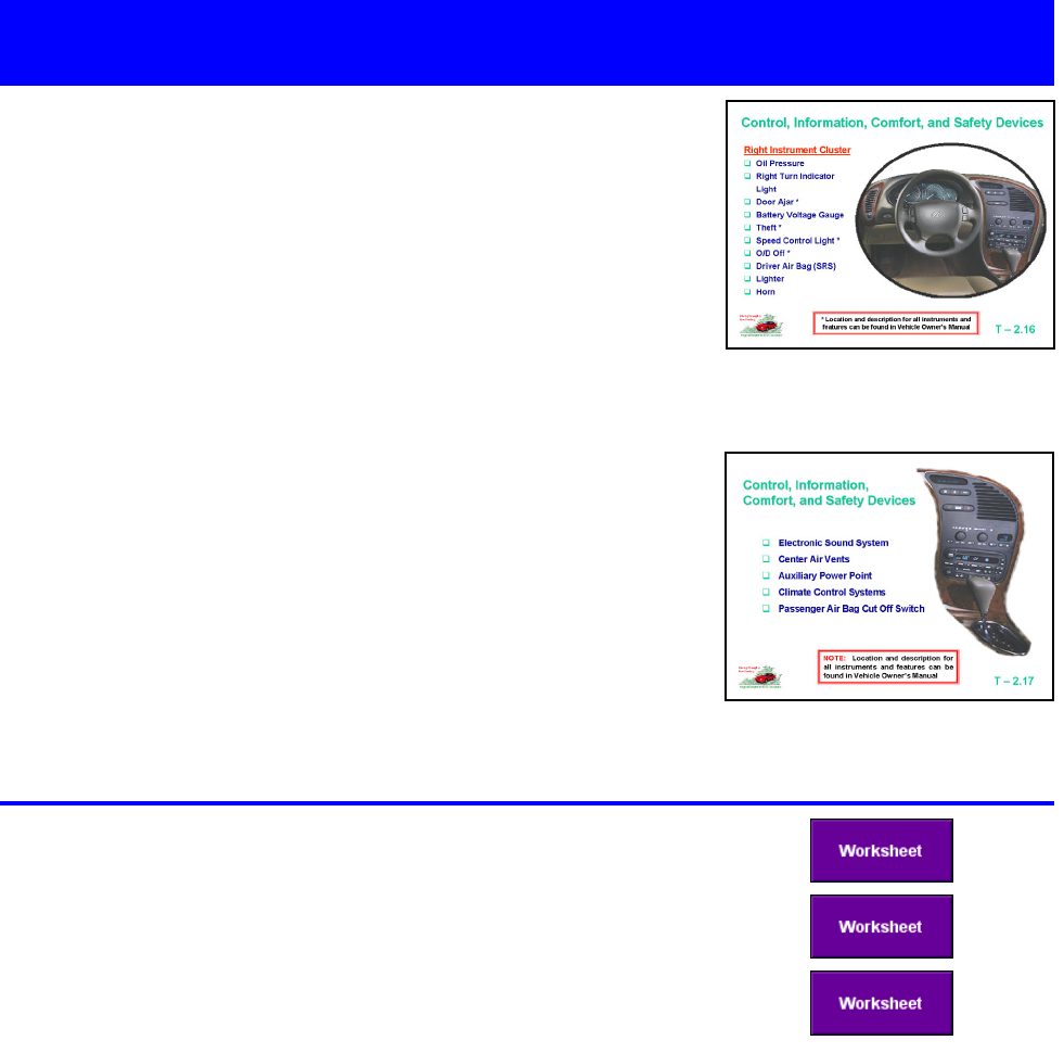
T-2.17 Control, Information,
Comfort, and Safety Devices
Topic: 2 Lesson: 2
...continued
T-2.16 Control, Information,
Comfort, and Safety Devices
Collect Worksheet W-2.3 “Control and Information Devices,”
Worksheet W-2.4 “Control, Information, Comfort, and Safety
Devices,” and Worksheet W-2.5 “Family Vehicle Instrument
Panel,” and use as assessment tools for this session.
Continue showing transparencies to identify the location and
function of the various control, information, comfort, and safety
devices.
Module Two—August, 2001 Page 17
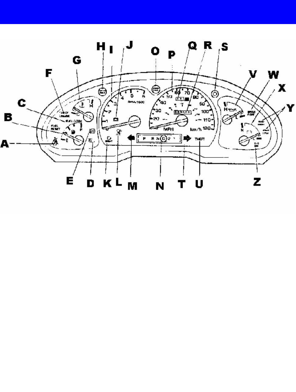
Topic: 2 Lesson: 2
Support Information
A. Safety Belt
B. Fuel Gauge
C. Fuel Door
D. Headlight Beam Indicator
E. Anti-lock Brake System
F. Check Engine Light
G. Temperature Gauge
H. Check Gauge
I. Tachometer
J. Battery Warning Light
K. Brake
L. Airbag
M. Left Turn Indicator
N. Gear Selection Indicator
O. Door Ajar
P. Speedometer MPH/km/h
Q. Trip Odometer
R. Odometer
S. Trip Odometer Reset
T. Right Turn Indicator
U. Theft
V. Oil Pressure Gauge
W. Speed/Cruise Control
X. Battery Voltage Gauge
Y. 4WD High/Low
Z. Overdrive On/Off
Module Two—August, 2001 Page 18

Instructor Activities
Time Frame
Module Two
Topic 3—Operating Vehicle Control Devices
50 minutes
(5-8 minutes)
(5-8 minutes)
(5-8 minutes)
(5-8 minutes)
(5-8 minutes)
(5-8 minutes)
5 minutes
50 Minutes Instructional Time
Prerequisites: Qualifies for Virginia Learner’s Permit
Review Module Two, Topic 3 Lesson Plans Prior to Lesson
Show Transparencies
T-2.18 "Operating Vehicle Control Devices”
T-2.19 "Operating Vehicle Control Devices”
T-2.20 "Operating Vehicle Control Devices”
T-2.21 "Safety, Communication, Comfort, and Convenience Devices”
T-2.22 "Safety, Communication, Comfort, and Convenience Devices”
T-2.23 "Safety, Communication, Comfort, and Convenience Devices”
Distribute and Review Student Worksheets
W-2.6 "Family Vehicle Equipment”
Review Module Assessments Prior to Lesson
W-2.5 "Family Vehicle Instrument Panel”
W-2.6 "Family Vehicle Equipment”
MA-2.1 “ Module Two Assessment”
Additional Resources (Media and/or Text)
Video: “Teaching Your Teens To Drive.” (AAA)
“Owner’s Manual” for the driver education vehicle
“Drive Right”
“Empower Yourself with Zone Control Driving”
“Handbook Plus”
“How to Drive”
“License To Drive”
“Responsible Driving”
Module Two—August, 2001 Page 19

Show Transparency T-2.18, T-2.19, and T-2.20 “Operating
Vehicle Control Devices” to discuss the operation of control
devices.
•
Steering position
• Steering wheel movement
•
Adjusting wheel height and angle
•
Accelerator pedal use
• Brake pedal use
• Gear selector lever
•
Location and use of parking brake
• Cruise and speed control
• Ignition switch
Knowledge and Skills
The student is expected to:
•
position the steering wheel and driver’s seat to allow for the operation of the vehicular controls.
• explain the function and operation of the steering wheel, accelerator, brake pedal, gear selection lever,
parking brake, cruise/speed control, and ignition switch.
Activities & Resources
Topic: 3 Lesson: 1
Operating Vehicle Control Devices
T-2.18 Operating Vehicle Control
Devices
T-2.19 Operating Vehicle Control
Devices
T-2.20 Operating Vehicle Control
Devices
Module Two—August, 2001 Page 20

Topic: 3 Lesson: 1
...continued
Support Information
Vehicle Control Devices
Controls perform the same function in each vehicle. However, location and characteristics not only vary
from one type of vehicle to another, but also between vehicles of the same make and model. It is critical to
remember that when operating any vehicle control, comfort, or communication device the driver’s attention
must not be diverted from the path of travel for more than an instant. The following provides general
information about each of the vehicle control devices:
Steering—The steering wheel is always turned in the direction the driver wants the vehicle to move,
whether moving forward or in reverse. However, the amount of steering input and energy needed will vary
according to the type of steering, number of turns lock to lock, power assist, and speed of travel. Target the
path of travel before starting to steer. It is wise to have the vehicle in motion when using the steering wheel.
Regardless of whether the driver’s hands grip the wheel in a balanced position on the upper or lower half of
the wheel, before one hand releases the wheel to adjust any information, comfort, or control device, the
hand not performing the action should be moved to the 7-8 or 4-5 o’clock position, depending on steering
wheel opening. The driver should not place one hand at the top of the wheel when moving forward due to
air bag injury potential and lack of balanced steering control.
Steering Wheel Adjustment
—The angle of the steering wheel is controlled by a lever located on the left or
right side of the steering column in some vehicles. Other vehicles permit the driver to change the angle of
the steering wheel by adjusting the steering column. An adjustment lever located on the bottom side of the
steering column, near the firewall, permits the driver to raise or lower the steering column to achieve a
better steering wheel angle.
Gear Selector Lever—In a vehicle with an automatic transmission, the gear selector lever is located either
on the steering column or on a console located between the front seats. In a vehicle with a manual
transmission, the shifting lever is located on the center console, on the floor to the right of the driver, or, in
older vehicles, on the right side of the steering column. Most vehicles have a lock release button to prevent
misshifting.
P—Parking, engine starting, and key removal
R—Reverse
N—Neutral
D—Normal driving (O/D overdrive on/off switch)
2—Stronger engine braking
L—Maximum engine braking
In most vehicles, the brake pedal must be depressed to shift gears. The overdrive switch is for selecting
either three-speed or four-speed transmission operation.
“Teaching Your Teens To Drive” (AAA) provides a video, student
guide, and parent guide that have three lesson segments
devoted to driver preparation, starting, and moving the vehicle.
This resource adds to the information presented in this segment.
Module Two—August, 2001 Page 21

Topic: 3 Lesson: 1
...continued
Parking Brake—
The parking brake is sometimes mistakenly referred to as an emergency brake. The
purpose of the parking brake is to hold a vehicle in place when it is parked and to protect the transaxle,
constant velocity joints, or transmission. Many new vehicle owner manuals indicate that it is important to
set the brake before putting the gear shifter in (P)ark. Driver education students should be taught to follow
this procedure. The parking brake may be either a foot-operated pedal located to the far left side of the
driver’s position or a hand-operated lever located to the right of the steering column or to the right of the
driver on the floor or center console. To set a foot-operated parking brake, push down firmly on the pedal.
Depending on the vehicle, one of two methods is used to release the brake. In some vehicles, the pedal is
pushed down until a click is heard, then the pedal is released. In other vehicles, the brake release lever is
located above the foot pedal on the underside of the dashboard. To set a floor or console mounted
parking brake, simply pull back firmly on the lever. To release the brake, press down the button located on
the top of the lever with the thumb and lower the lever.
Cruise/Speed Control—This device allows a driver to select and travel at a set speed without having to
keep a foot on the accelerator or the brake. The controls are located either on the steering wheel or a
stem on the left side of the steering column. The control options include on/off, set/accelerate, and coast.
Cruise control allows you to cruise at speeds over 25 mph.
Ignition Switch—This switch locks the steering wheel and shifting lever, and enables the driver to start
and turn off the engine or use the accessories. The ignition is located on the right side of the steering
column near the dashboard or in the dashboard.
Engine Immobilizer System—This is a theft prevention system. The engine will start only when the
electronic code in the key’s transponder chip corresponds to the registered ID code for the vehicle. The
system is set automatically when the key is removed from the ignition switch. An indicator light will flash to
show that the system is set.
Accelerator Pedal—
This foot-operated pedal is suspended from the firewall on the right side of the
driver’s position. Speed is controlled by adjusting even pressure on the pedal. Some vehicles have
electronic adjustments for the foot pedals. Extensions are available to meet special needs of the driver in
reaching the pedal with the foot in a proper position.
Brake Pedal—This pedal is located to the left of the accelerator. The driver slows the vehicle by applying
a squeezing pressure on the pedal with the heel of the foot on the floor. How much and how rapidly the
vehicle slows is determined by how much pressure the driver applies to the brake pedal and the friction
between the tires and road surface. Brake pedal extensions are available for short-statured drivers, which
allow them to sit at least 10” away from the airbag.
Module Two—August, 2001 Page 22
Module Two—August, 2001 Page 23
Notes

Knowledge and Skills
The student is expected to explain the function and operation of the mirrors, safety belts, head
restraints, horn, turn signal, door locks, hazard flashers, windshield wipers/washer, headlights, hood
release, trunk release, heater/ventilation/air conditioner, and seat adjustment controls.
Activities & Resources
Show Transparency T-2.21, T-2.22, and T-2.23 “Safety,
Communication, and Convenience Devices” to discuss the
operation of safety, communication, and convenience control
devices.
•
Rear view and side view mirrors
• Safety belts
•
Head restraints
•
Horn location and use
• Turn signal and lane changer device
• Door locks
•
Hazard flashers
• Windshield wipers and washer
• Headlight and daylight running lights
•
Hood release
•
Trunk release
• Heater, ventilation, and air conditioner (HVAC)
• Seat adjustment controls
Provide Worksheet W-2.6 “Family Vehicle Equipment” to
reinforce this topic area.
Topic: 3 Lesson: 2
Operating Vehicle Control Devices
T-2.22 Safety, Communication,
Comfort, and Convenience
Devices
T-2.21 Safety, Communication,
Comfort, and Convenience
Devices
T-2.23 Safety, Communication,
Comfort, and Convenience
Devices
Module Two—August, 2001 Page 24

Topic: 3 Lesson: 2
Support Information
Mirrors—Adjust the mirrors, inside and outside. For vehicles equipped with remote controlled outside
mirrors, these controls may be located on the left side of the dash, the driver’s side arm rest, or center
console. However, no matter how the mirrors are adjusted, there are areas that cannot be seen and require
drivers to turn their heads to check prior to making a move to the left or right.
The Blindzone and Glare Elimination (BGE) technique promoted by George Platzer (1996), an automotive
safety engineer and member of the Society of Automotive Engineers (SAE), may be used to train new
drivers. The inside rear view mirror becomes the primary mirror, and the left and right side view mirrors
become directed to side view use only. The driver can move his head toward the window to see the right and
left sides of the vehicle when pulling from the curb. The BGE setting allows the driver to have two useful
views in the side mirror, and the in-car instructor can use the right side mirror view as a rear view mirror. For
more information go to the Society for Automotive Engineers’ website at http://www.sae.org.
Inside rearview mirrors have a night driving position to reduce headlight glare.
Safety Belts—While safety belts protect occupants in a crash, they serve an equally important role of
keeping the driver firmly in place behind the steering wheel, allowing better control of the vehicle. For
maximum protection, the safety belt should be positioned under jackets, coats, sweaters etc., as low on the
hips or thighs as possible. After fastening the belt, grasp the shoulder belt and pull upward to take up the
slack in the belt across hips. Make sure that all passengers do the same.
Head Restraint—All new vehicles are equipped with head restraints to help reduce whiplash injuries if the
vehicle is struck from the rear. Some vehicles are equipped with head restraints that can be adjusted up or
down to position the restraint behind the middle of the occupant’s head. Drivers should be sure that the
restraint is adjusted to a position above the ear level to avoid serious neck injury in a rear collision. Some
vehicles are equipped with head restraints that are built into the top of the seat and cannot be adjusted.
Horn—The horn is generally operated by pressing a button located on a steering wheel cross bar or on the
pad on the lower half of the steering wheel above or below the air bag cover. It is usually marked with the
horn symbol to indicate the location.
Turn Signal Lever—The turn signal lever has two uses. Located on the left side of the steering column, the
lever is moved up to signal a movement to the right and down for a movement to the left. While the signal
will cancel after a turn, the driver may have to cancel the signal manually after a slight turn. The signal is
used to indicate a lane change by moving the lever halfway up or down with the thumb hooked on the
steering wheel. The signal begins to work as the halfway point is reached and can be manually held in this
position or locked prior to a lane change. Manually holding in position allows the driver to easily release the
lever prior to the movement so that a signal to turn will not be confused with the lane change or merge.
Door Locks—
In vehicles equipped with manual locks, each door has its own locking device. An additional
master control is usually located on the driver side arm rest in vehicles with electric door locks. Child safe
rear door locks are an option.
Wireless remote controls not only lock and unlock doors, they often have a panic switch. When the panic
switch is pushed, the horn blows and the exterior lights flash to attract attention and summon help in case of
emergency.
Hazard Flasher—
The purpose of the hazard flashers is to warn other drivers of a problem and to increase
their awareness of the presence of your vehicle. The switch for the lights is usually located on the top or right
side of the steering column or on the dash. When operated, both front and rear turn signal lights flash.
Module Two—August, 2001 Page 25

Topic: 3 Lesson: 2
...continued
Vehicle Lights—
Some vehicles are equipped with daylight running lights, which may operate the
headlights without having the taillights on. It is recommended by the National Highway Traffic Safety
Administration (NHTSA) to use the headlights whenever the vehicle is moving, especially when not
equipped with the daylight running lights. The light switch is often located on a steering stalk or on the dash
panel to the left and is often a multi-purpose switch for parking lights, headlights, high beam, or low beam.
A panel switch is often used to adjust the brightness of the dash panel lights and interior lights.
Automatic light control sensors are available on some vehicles and turn headlights on or off depending on
the darkness of the surroundings.
Front fog lights are an option on some vehicles and come on only when headlights are on low beam.
Windshield Wipers and Washers—This control is frequently located on the turn signal lever. Two
switches are often involved, one that controls the speed of the wipers and a second that controls the
washer fluid.
Hood Release—This lever is usually located on the left side of the driver’s compartment under the
instrument panel. In some vehicles it is located under or just to the right of the steering column. To open
the hood, a second latch located under the hood of the vehicle must be released.
Trunk Release—An option in some vehicles is to have a trunk release lever located on the floor just to the
left of the driver’s seat. In other vehicles, the release mechanism is a button located in the glove box, or is
a feature included on a keyless entry remote control mechanism.
Heater, Ventilation, and Air Conditioner—These control switches are located in a duster on the
instrument panel. Some vehicles have a separate switch located on the instrument panel that operates a
rear window defroster.
Seat Adjustment Controls—If manually controlled, the adjustment lever to move the seat forward or back
is typically located at the lower front or right side of the driver’s seat. A second lever or knob located on the
left side of the seat in some vehicles allows the driver to change the angle of the seat back. In vehicles with
electric power seats, the controls are usually located on the lower left side of the driver’s seat or in a control
cluster located on the side door panel.
Power Windows—
Work when the ignition switch is in the “on” position. Some vehicles have an automatic
operation feature for the driver’s side window. The window will open all the way when pushed down. A
wireless remote is an option.
Window Lock Switch—
Push in the window lock switch and passengers’ windows can not be operated.
Other Features
• Outside and inside temperature indicators
• Average vehicle speed
•
Average fuel consumption
• Instantaneous fuel consumption
• Driving time
•
Power outlets for accessories
•
Garage door opener
• GPS—Global positioning systems
Module Two—August, 2001 Page 26

Instructor Activities
Time Frame
Module Two
Topic 4—Vehicle Balance Considerations
25 minutes
(3-5 minutes)
(3-5 minutes)
(3-5 minutes)
(3-5 minutes)
(3-5 minutes)
(3-5 minutes)
(3-5 minutes)
(3-5 minutes)
10 minutes
25 Minutes Instructional Time
Prerequisites: Qualifies for Virginia Learner’s Permit
Review Module Two, Topic 4 Lesson Plans Prior to Lesson
Show Transparencies
T-2.24 "Controlling Vehicle Balance”
T-2.25 "Controlling Vehicle Balance”
T-2.26 "Controlling Vehicle Balance”
T-2.27 "Vehicle Control”
T-2.28 "Vehicle Control”
T-2.29 "Vehicle Control”
T-2.30 "Vehicle Control”
T-2.31 "Vehicle Control”
Distribute and Review Student Worksheets
W-2.7 “Vehicle Balance Basics”
Review Module Assessments Prior to Lesson
W-2.7 “Vehicle Balance Basics”
MA-2.1 “Module Two Assessment”
Additional Resources (Media and/or Text)
“In Control: Technical Aspects of a Vehicle ”
Video: “In Control: America’s Driving Reference ” (J.B. Heimann Productions,
Instructional Video, 2219 C Street, Lincoln, NE 68502;
(800)228-0164)
Video: “Teaching Your Teens to Drive” (AAA)
“Teaching Your Teens to Drive” Parent/Teen Handbook
“Drive To Survive”
“Survival Behind the Wheel”
“How to Drive”
“Handbook Plus”
“Going Faster”
“Bondurant Behind the Wheel”
Module Two—August, 2001 Page 27

Show Transparency T-2.24 “Controlling Vehicle Balance” to
discuss vehicle balance concepts and how balance is affected
by driver seating position, steering input, acceleration, and
brake application.
Knowledge and Skills
The student is expected to:
•
define and explain vehicle balance.
• describe how seating position affects the ability to control vehicle balance.
•
describe how steering, braking, and acceleration each affect vehicle balance and list ways to
compensate to maintain vehicle balance under the forces of these conditions.
Activities & Resources
Provide Worksheet W-2.7 “Vehicle Balance Basics” as a Topic
4 assessment tool and classroom activity.
Topic: 4 Lesson: 1
Vehicle Balance Considerations
Use Transparency T-2.25 “Controlling Vehicle Balance” to
continue discussing vehicle balance concepts.
• Steering wheel balance
•
Changes in steering ratios
• Precision steering, braking, and acceleration
T-2.24
Controlling Vehicle Balance
T-2.25
Controlling Vehicle Balance
Module Two—August, 2001 Page 28

Topic: 4 Lesson: 1
...continued
Show Transparency T-2.26 “Controlling Vehicle Balance” to
continue discussing vehicle balance concepts.
•
A balanced driver seating position
• Vehicle changing balance from side to side (roll)
T-2.26 Controlling Vehicle Balance
Support Information
Vehicle Balance
The most neglected area of traffic safety education is the area of vehicle balance instruction. Few
instructors adequately teach the importance of using kinesthetic senses when driving an automobile.
However, a driver uses the feeling of motion consistently to judge acceleration, deceleration, and the loss
of traction. The only other sense used more to safely operate a vehicle is vision. Vehicle balance refers to
the distribution of the weight of the vehicle on the tires as they meet the ground. This downforce of the tire
patch to the roadway is affected by tire pressure and the suspension geometry. The ideal tire patch size
and balance for a vehicle is only reached when the vehicle is motionless. As soon as motion occurs,
changes to the vehicle balance or weight on the tire patches changes. A transfer of weight from one point
of the vehicle to another is caused by acceleration, deceleration, cornering, or a combination of these
actions. If there is no acceleration or deceleration, the vehicle is traveling at a constant speed or stopped,
the suspension is set on center and the steering and traction condition is considered to be in balance.
Requirements for Maintaining Vehicle Balance
•
Balance maintained through precise steering movements, smooth and progressive acceleration, and
controlled brake application
• Body position which allows the feet, legs, arms and hands to maintain a stable seat position and
maximize vehicle movement feedback (kinesthetic feedback)
Maintaining vehicle balance results from the driver’s reaction to the vehicle’s suspension changes and
center of weight transfers. Basically, the weight of a vehicle can be concentrated on one of three points on
the chassis based on speed changes—the front of the chassis (over the front tire patches), the rear of the
chassis (over the rear tire patches), the center of the chassis (distributed equally over the front and rear tire
patches); or can be concentrated on one of two points on the chassis based on steering or surface
changes—to the right of center (right two tire patches), or the left of center (left two tire patches). The
magnitude of these weight changes and the driver’s ability to maintain control of the vehicle is influenced
by the rate of acceleration, brake application pressure, steering input, surface traction, or combinations of
these factors.
Optional Resource “In Control: Vehicle Technical Aspects” (J.B.
Heimann Production) provides information from Sam Posey and
Sandy Stevens about seating position, aspects of pitch, roll,
vehicle understeer, vehicle over-steer, and antilock brakes. It
supplements the information presented in this segment.
Module Two—August, 2001 Page 29

Topic: 4 Lesson: 1
...continued
Students must understand that when driving newer model cars, the distance the steering wheel must be
moved to perform most maneuvers is substantially less than was required with most cars during the
1980s and many models in the early 1990s. The number of steering wheel turns, lock to lock, has in
most cases been reduced from four to five turns to two to three turns. The lock to lock configuration
reduction is a result of smaller steering wheel sizes and rack and pinion steering geometry changes.
Without appropriate adjustment on the part of drivers, steering too quickly in combination with sudden
brake application appears to have become a problem, particularly in the occurrence of single vehicle, run-
off-roadway crashes.
As a result of the off-road crash potential, the use of hand-over-hand steering is no longer recommended
and, instead, hand-to-hand steering is recommended. Hand-over-hand is still recommended, however, in
slow movement activities when vision is limited, such as perpendicular parking, or very fast action
movements, such as traction loss recovery. Since drivers operate different types of vehicles, it becomes
critical to teach more than one steering technique to new drivers.
Seating Position—In order to establish vehicle balance and improve ability to see, drivers should sit in a
comfortable, erect position squarely behind the steering wheel. Adjust seat height so that the top of the
steering wheel is in line with the top of the shoulders. The top of the wheel should never be more than
one inch higher than the top of the shoulders. (In vehicles without power seats and/or adjustable steering
columns or tilt steering wheels, some drivers will need to use a wedge-shaped driver’s cushion.)
Proper distance from the steering wheel can be determined by extending the arm straight forward and
adjusting the position of the seat, forward or backward, until the top of the steering wheel is in line with
the wrist joint.
Drivers under five feet five inches in height or with short legs may need to use brake and accelerator
pedal extensions to comfortably reach and operate the pedals and maintain a distance of 10 inches
between their body and the steering wheel to reduce the chance of injury in the event of air bag inflation.
Changing Vehicle Balance from Side to Side (Roll)
Sudden steering, acceleration, or braking inputs can affect vehicle balance from side to side (vehicle roll).
• Steering Movements—Weight or center of mass shifts to left or right side of vehicle depending on
speed, traction, and amount of steering input. Occupants may or may not feel forward lifting
movement from the corner of the vehicle opposite the direction of the turn.
•
Brake and Steering Combinations—Depending on degree of steering and brake input, braking may
improve traction, such as in trail braking through a turn, when performed at an appropriate speed.
However, applying the brakes when cornering at too high a speed has little effect relative to slowing
the vehicle, but may have a very noticeable effect of producing traction loss due to severe weight
shift to the front tire on the inside of the curve.
Changing Vehicle Balance from Front to Rear (Pitch)
Sudden steering, acceleration, or braking inputs can affect vehicle balance from front to rear. When
acceleration is applied, weight or center of mass is transferred toward the rear of the vehicle. If
acceleration is sudden and hard, there is a noticeable drop of the rear of the vehicle and occupants feel
rearward weight thrust.
• Releasing Brake—
Simply releasing pressure from the brake pedal results in a shift of weight to the
rear.
• Covering Accelerator—The purpose of covering the accelerator is to provide a smooth transition
from brake release to progressive acceleration. It is similar to trail braking in that speed and vehicle
balance are maintained prior to braking.
Module Two—August, 2001 Page 30

Topic: 4 Lesson: 1
...continued
• Light Accelerator Pressure—The purpose of light accelerator pressure is to maintain weight
balance while maintaining slow forward motion or reducing speed gradually with minimal weight shift.
•
Progressive Accelerator Pressure—Firm, steady acceleration will increase speed and gradually
shift balance of vehicle to the rear suspension. This action eases steering control and improves rear
wheel traction moving out of a turn or curve.
• Thrust Accelerator Pressure—
A firm push or thrust of accelerator used to shift more weight to the
rear wheels for traction, or to cause a shift to a lower gear in a vehicle with an automatic transmission
to increase the rate of acceleration. This process is sometimes needed when passing or changing
lanes in higher speed traffic situations.
Changing Vehicle Load from Rear to Front (Pitch)
Sudden steering, acceleration, or braking inputs can affect vehicle balance from rear to front. When
brakes are applied, weight or center of mass is transferred to the front of the vehicle. If braking is hard,
there is a noticeable drop of the hood and rise of the rear of the vehicle and occupants feel forward
movement. The most efficient way to slow or stop your vehicle is to brake while traveling in a straight
line. This allows the braking force to have an evenly distributed effect on all four wheels.
The ability to apply the correct pressure to the brake pedal is learned through experience and practice.
However, each vehicle has a somewhat different “feel” with which a driver must become familiar. Apply
too little pressure and the vehicle will not stop at the desired spot or within the distance available. Apply
too much pressure and the brakes may lock up, and traction and directional control may be lost.
The key to good braking technique is to stabilize the foot and control brake pressure with the forces of the
ankle and toes rather than thigh muscles. To facilitate this action place the heel of the foot on the floor in
front of the brake pedal in such a manner that the foot forward of the ball makes contact with the pedal.
This position better enables drivers to use the toes to make fine adjustments to pedal pressure and to
pivot the foot more smoothly back and forth between the brake and accelerator. This also allows the
driver to rest the right side of the foot against the center console or center hump for better control of
speed while their foot is on the accelerator.
•
Releasing Accelerator—Simply releasing pressure on the accelerator results in a shift of weight to
the front. The affect on the reduction in speed tends to be more noticeable in vehicles with rear
wheel drive than in front wheel drive vehicles equipped with transaxles.
• Cover Brake—
The purpose of covering the brake is to provide a smooth transition from acceleration
to braking. It is similar to trail braking in that speed and vehicle balance are maintained prior to
braking.
• Controlled Braking (Squeeze On)—Braking is done with sufficient brake pressure needed to slow
the vehicle, while maintaining balance to avoid traction loss to front or rear wheels. Remember that
directional control (steering) becomes more difficult when using hard brake application.
• Threshold Braking—Threshold braking is used to maximize the braking effect of the vehicle, lifting
(unloading) the rear suspension, and lowering (loading) the front suspension, to provide maximum
traction to the front tires for braking just short of lock up. If lock up does occur, steering control is
regained by releasing brake pressure very slightly (2-3 degrees). As with controlled braking, control
of the brake pedal is best maintained if the heel is on the floor.
• Trail Braking (Squeeze Off)—
Trail braking is used to maintain speed and balance of the vehicle
when steering is required prior to turning at an intersection or in a curve. This technique is often used
in combination with or at the end of controlled or threshold braking.
Module Two—August, 2001 Page 31

Use Transparency T-2.27 “Vehicle Control” to illustrate and
discuss how sudden steering or improper combinations of
braking and steering affects vehicle balance at any speed.
Knowledge and Skills
The student is expected to:
• describe how changes in vehicle balance from side to side, front to rear, and rear to front affect
vehicle balance.
• describe the correct hand positions and steering techniques recommended when performing driving
maneuvers.
Activities & Resources
Show Transparency T-2.28 “Vehicle Control” to discuss load
transfer during braking, cornering, and steering at dangerously
high speeds or while using an improper combination of braking
and steering.
Show Transparency T-2.29 “Vehicle Control” to discuss load
transfer during rear end swings to the right or left, resulting in a
yaw (spinning) condition.
Topic: 4 Lesson: 2
Vehicle Balance Considerations
T-2.27 Vehicle Control
T-2.28 Vehicle Control
T-2.29 Vehicle Control
Module Two—August, 2001 Page 32

Topic: 4 Lesson: 2
...continued
“In Control: Vehicle Technical Aspects” (J.B. Heimann
Production) provides information from Sam Posey and Sandy
Stevens about seating position, aspects of pitch, roll, vehicle
understeer, vehicle oversteer, and antilock brakes. It
supplements the information presented in this segment.
Show Transparency T-2.30 “Vehicle Control” to discuss load
transfer during braking, cornering, and steering at dangerously
high speeds or using an improper combination of braking and
steering.
Show Transparency T-2.31 “Vehicle Control” to discuss using
the steering wheel in a smooth and precise manner.
Collect Worksheet W-2.7 “Vehicle Balance Basics” as an
assessment tool for this topic area. Additional evaluation and
assessment questions concerning this topic are located in the
Module Assessment MA-2.1 “Module Two Assessment.”
T-2.30 Vehicle Control
T-2.31 Vehicle Control
Module Two—August, 2001 Page 33

Topic: 4 Lesson: 2
Support Information
Steering Wheel Control
Due to changes in steering ratios and effort needed to turn the wheel, recommendations relative to hand
position on the steering wheel have become more flexible. In order to maximize vehicle control, normal
steering control involves the balance of the steering wheel to avoid sudden movements and minimize
steering wheel reversals.
• Hand Position—
Placing the hands at shoulder height (the left hand between 9 and 10 o’clock and the
right hand between 2 and 3 o’clock allows for balanced shoulder strength to control the wheel).
Placing the left hand between 7 and 9 o’clock and the right hand between 3 and 5 o’clock with the
upper arms resting against the rib cage also improves stability by lowering the body’s center of gravity
and reduces unintended steering wheel reversals. Because of its more natural seating position, it also
facilitates keeping both hands on the wheel and reduces upper and lower back pain often associated
with trip driving. The driver’s grip of the steering wheel should be firm but gentle. Grip the steering
wheel by the outside rim. For greater sensitivity to information communicated by the vehicle, use
fingers instead of palms of hands and keep thumbs up along the face of the steering wheel. Never
turn the wheel while gripping it from the inside of the rim, hand facing outward.
• Steering Techniques—
To steer when turning and moving forward, use both hands—one pushing; the
other pulling. In general, when backing and turning, use one hand. Four types of steering movements
will be used during various in-car exercises. They are hand to hand, limited evasive steer, hand over
hand, and one hand steer.
•
Hand to Hand Steering—Sometimes referred to as Push/Pull/Feed Steering but should not be
confused with shuffle steering. Hand to hand steering permits the driver to make steering inputs
ranging from very minor, one to two degrees, to gross adjustments up to a half turn of the wheel, while
keeping both hands on the wheel for precision adjustments.
If turning through a slight curve, both hands will typically retain their original grip on the wheel, making
only slight finger or wrist adjustments as necessary to maintain path of travel.
However, when moving through a turn, the hands may move up to 165 degrees (neither hand moves
beyond the 6 or 12 o’clock positions). Depending on whether the driver initiates the turn by pulling the
wheel down from the 3 or 9 o’clock position toward 6 o’clock, or pushing the wheel up from the 5 or 7
o’clock position toward 12 o’clock, the opposite hand slides up or down as appropriate to provide
additional input or to stabilize steering. The process is reversed to return to a straight path. The wheel
is not allowed to slip through the fingers to straighten when coming out of a turn and both hands are
always on the wheel to make adjustments as necessary.
Hand to hand steering is particularly well suited for precision maneuvers, steering through curves,
intersection entry and exit, and front wheel traction loss control (vehicle understeer).
• Hand Over Hand Steering—
Hand over hand steering is particularly well suited when speed of the
steering movement is critical such as skid recovery in a rear wheel traction loss (vehicle oversteer).
When used to control or recover from a skid, it is important to hold the wheel in a pattern that allows
the driver to use the upper left third of the wheel when steering to the left and the upper right third
when turning right. This procedure allows for maximum movement of the wheel with knowledge of its
neutral position. Hand over hand steering is also useful when maneuvering in a space with limited
sightlines, such as perpendicular parking in a congested shopping center. When using hand over
hand steering, quick movements of the hands are recommended on entry to the maneuver, with
smooth slow movements when returning the wheel upon completion of the maneuver.
Drivers should be aware that employing hand over hand steering under all conditions does expose one
Module Two—August, 2001 Page 34

Topic: 4 Lesson: 2
...continued
to some additional risk of injury to arms, hands, and/or face in the event of a crash that results in air
bag inflation. Use of hand over hand as the primary steering technique also raises the risk of off-road
crash occurrences.
• Limited Evasive Steering—Crash studies indicate that inattention to the path ahead was the
primary cause of nearly 21% of the reported crashes. However, 5.6% occurred as a result of failure
to make a quick turn, or improper evasive action. Whether performed at low or high speed, a quick
turn results in a shift of weight or center of mass to the left or right side of the vehicle.
Speed of travel and steering input have a direct influence on the level (increase) of weight transferred
to the front corner opposite the direction of the turn with a reduction in the weight to the rear,
particularly on the side in the direction of the turn.
When an error has been committed and closure is occurring at higher speeds, the quickness and
amount of steering input needed to make a 12-foot lane change increases. This additional sudden,
steering input coupled with the speed of travel, unless dampened by a smooth, rapid, limited steering
effort, is capable of generating sufficient weight transfer to cause a loss of directional control.
Important Points to Remember
- In an evasive action, limited steering input of no more than 180 degrees (touch of the arms) must
be quick and smooth with limited return steering to maintain vehicle balance.
- At higher speeds, the driver may control brake prior to initiating the steering action to transfer
weight to the front wheels, but must come off the brake or trail brake while steering for avoidance.
As the speed increases, less steering input is needed to move the vehicle to the left or right.
- Keep in mind that if the vehicle is equipped with ABS, stay with the brake while performing the
limited steering inputs.
- The initial steering input moves the front of the car while the second input moves the rear of the
vehicle. It is critical to move the wheel back to the neutral position to stabilize the vehicle within the
lane.
• One Hand Steering—Movement of the steering wheel with one hand is recommended only for
backing maneuvers which do not require full left or right turns or when operating information, safety,
or comfort devices.
Backing and steering with one hand requires shifting one’s hip and seat position so the driver’s head
can be turned to see past the head restraint. To improve balance, the driver’s right arm is often
draped over the back of the seat. Visual checks to the front should be made prior to starting the
backing maneuver. The left hand grips the steering wheel near the top and is moved in the direction
that the driver wishes the rear of the vehicle go. The left hand at the bottom may be used to back a
trailer. Sharp turns while backing may require the use of both hands. Since it is more difficult to
maintain steering control when backing, all reverse movements should be made at slow speed.
Module Two—August, 2001 Page 35
Module Two—August, 2001 Page 36
Notes

Instructor Activities
Time Frame
Module Two
Topic 5—Standard Vehicle Reference Points
30 Minutes Instructional Time
Prerequisites: Qualifies for Virginia Learner’s Permit
Total Parental Involvement: 7 Hours
Review Module Two, Topic 5 Lesson Plans Prior to Lesson
Show Transparencies
T-2.32 "Targeting and Visual Requirements”
T-2.33 "Determining Vehicle Operating Space”
T-2.34 "Traditional Mirror Views and Blind Spots”
T-2.35 "Mirror Blind Spot and Glare Elimination”
T-2.36 "Standard Referencing Points”
T-2.37 "Front Limitation”
T-2.38 "Front Limitation”
T-2.39 "Front Limitation”
T-2.40 "Rear Limitation”
T-2.41 "Rear Limitation”
T-2.42 "Rear Limitation”
T-2.43 "Right Side Limitation”
T-2.44 "Right Side Limitation”
T-2.45 "Left Side Limitation”
T-2.46 "Left Side Limitation”
T-2.47 "Lane Position # 1”
T-2.49 "Lane Position # 2”
T-2.50 "Lane Position # 2”
T-2.51 "Lane Position # 3”
T-2.52 "Lane Position # 3”
T-2.53 "Lane Position #1”
T-2.54 "Lane Positions”
T-2.55 "Lane Positions”
T-2.56 "Possible Lane Positions”
T-2.57 "Angle Parking”
T-2.58 "Standard Reference Points”
Distribute and Review Student Worksheets
W-2.8 "Standard Vehicle Reference Points”
Review Module Assessments Prior to Lesson
MA-2.1 “ Module Two Assessment”
Additional Resources (Media and/or Text)
“Empower Yourself with Zone Control Driving, (”Mottola)
Video: “Targeting” (IDS)
Video: “Reference Points,” (IDS)
Interactive Driving Systems, Inc (IDS), Frederick R. Mottola,
P.O. Box 98, Chesire, CT 06410, Orders: (800) 764-7767
30 minutes
(3-5 minutes)
(3-5 minutes)
(2-3 minutes)
(2-3 minutes)
(2-3 minutes)
(2-3 minutes)
(1-2 minutes)
(1-2 minutes)
(2-3 minutes)
(1-2 minutes)
(1-2 minutes)
(2-3 minutes)
(1-2 minutes)
(1-2 minutes)
(1-2 minutes)
(2-3 minutes)
(2-3 minutes)
(1-2 minutes)
(2-3 minutes)
(1-2 minutes)
(2-3 minutes)
(1-2 minutes)
(1-2 minutes)
(1-2 minutes)
(2-3 minutes)
(1-2 minutes)
5 minutes
Module Two—August, 2001 Page 37
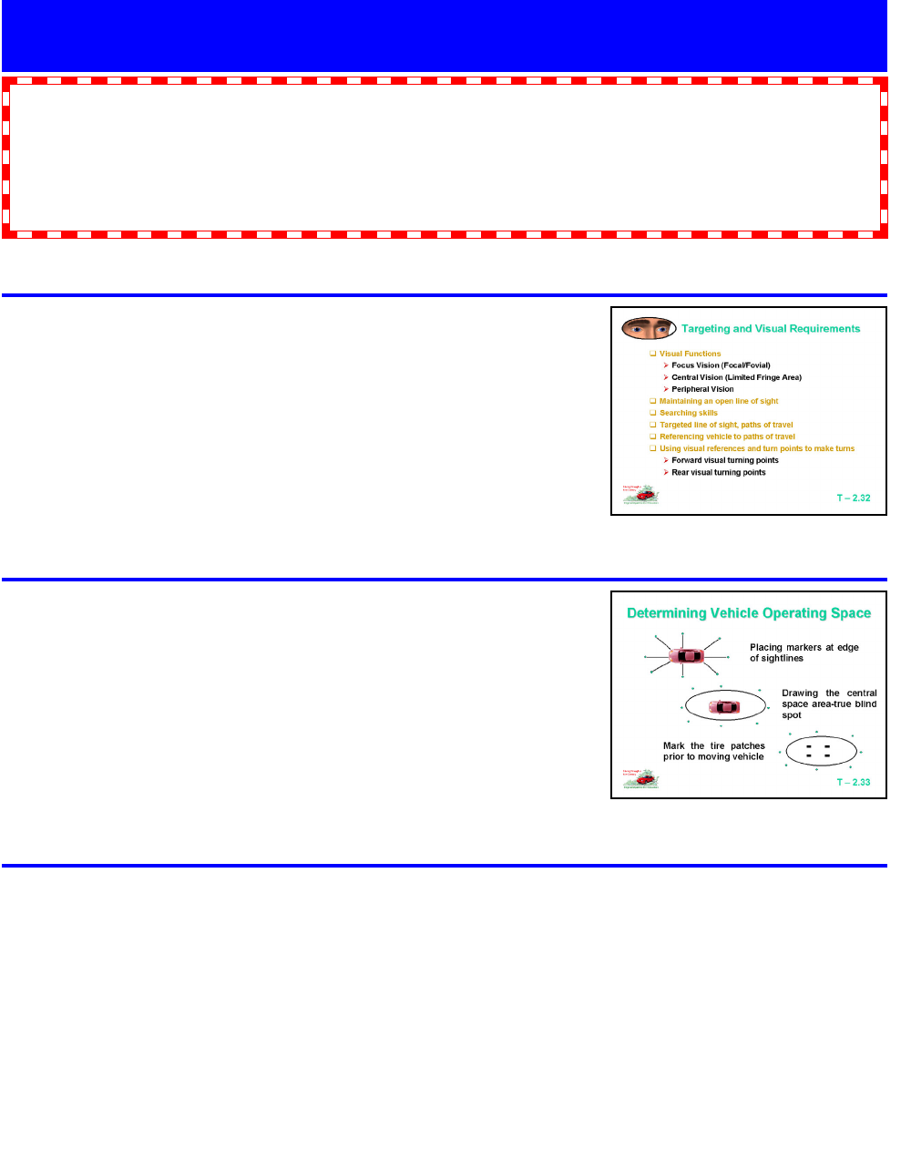
Use Transparency T-2.32 “Targeting and Visual
Requirements” to discuss the vision and perception
requirements necessary for the safe operation of a vehicle.
Knowledge and Skills
The student is expected to:
•
define visual target with regard to path of travel.
• assess and analyze the path of travel of a vehicle, and the line of sight while seated in a vehicle.
• compare and contrast traditional mirror settings and contemporary mirror settings with regard to blind
spot elimination and glare elimination.
Activities & Resources
Show Transparency T-2.33 “Determining Vehicle Operating
Space” to discuss the space visible and not visible around the
vehicle.
Visible Space
•
One car-length to the front
•
Two car-lengths to the rear
• One car-width to the left
•
Two car-widths to the right
Topic: 5 Lesson: 1
Standard Vehicle Reference Points
T-2.32
Targeting and Visual Requirements
T-2.33 Determining Vehicle
Operating Space
Have students participate in a Vehicle Space Demonstration
(Pages 44-47):
• Student gains a perspective of space that is visible to
driver.
•
Student learns that the driver must look for things that can
be seen.
• Because the area to the front, side, and rear is so large,
reference points will help.
• Student will recognize that driving takes place in the future
(targeting) and the past (mirrors). It is critical not to try to
look where the vehicle is, as this area is not visible to the
driver.
Module Two—August, 2001 Page 38

Topic: 5 Lesson: 1
..continued
“Targeting” (IDS) may also be used to introduce or review
targeting skills. The video supplements the information
presented in this lesson.
Use Transparency T-2.35 “Mirror Blind Spot and Glare
Elimination” to discuss mirror settings that eliminate blind spots
and reduce headlight glare when driving at night.
T-2.35 Mirror Blind Spot and Glare
Elimination
Show Transparency T-2.34 “Traditional Mirror Views and Blind
Spots” to discuss the blind spots when using traditional mirror
settings.
T-2.34 Traditional Mirror Views
and Blind Spots
Module Two—August, 2001 Page 39

Topic: 5 Lesson: 1
Support Information
Vision and Perception Requirements
In this module, there is an emphasis on the importance of directed attention, maintaining an open line of
sight, searching skills, and targeting a line to maintain a safe path of travel. It is critical that students
understand how an inadequate or improper visual search, lack of understanding of vehicle dynamics,
failure to respond, or a delayed response to a threatening object or condition contributes to driver crash
involvement.
Referencing Vehicle to Path of Travel—Visual Functions
• Central (Focal) Vision—used to read and identify distinct objects, and covers about three percent of
one’s visual field
•
Fringe Vision—used to judge depth and position
• Peripheral Vision—conical in shape around the other vision fields
Maintaining an Open Line of Sight—Searching Skills
•
Using visual references and turn points to make turns
• Forward visual turning point
• Rear visual turning point
•
Targeted line of sight, paths of travel
• Referencing vehicle to paths of travel
Introduction to Targeting
A fixed object that appears at the end and in the center of the path you intend to drive. To select a target,
first decide where you want the vehicle to travel. Then aim for an object in the center of that path.
Advantages of Targeting
•
Allows driver to visualize the space they intend to occupy
•
Helps driver start learning to use a searching process
• Gets driver to look far ahead, rather than close to vehicle
• Allows driver to plan ahead
•
Increases steering precision and reduces steering reversals
• Develops skid avoidance skills
Target Area
The target area is the driving environment to the left and right of where the target is located. Searching
the target area for driving related information is more important than trying to identify a specific target.
Identification of a specific target is only necessary while learning what a target is and how to identify one.
Target Area to Target Area
Target Area Searching requires identification of the condition of the target area as open or closed, red light
or green, stopped traffic or moving, curve or hill crest, left curve or right curve, to give you a clear picture of
what to expect ahead in the vehicle’s targeting path.
After knowing what the condition is in your target area, you then should assess your 12-15 second range
to see what zone changes can or do affect your targeting path. Make assessments of your other zones to
see what your options are. Then select the best lane position and get the best speed control in order to
achieve the lowest degree of risk en route to the target area. As you get within 4-6 seconds of a zone
change, you reevaluate it to insure best control.
Closer to the target area, you re-evaluate the condition of the target area and begin assessing your next
target area and the zone changes that you will encounter en route. This process of searching from one
target area to the next target area is repeated continually.
Module Two—August, 2001 Page 40

Topic: 5 Lesson: 1
...continued
Preventing Blind Spot Crashes and Eliminating Mirror Glare
Most drivers learned about blindzones (blind spots)
in a driver education class and to look over their
shoulders before changing lanes. Your first real encounter with a blindzone was probably when you tried to
change lanes and got a horn blast in your ear. The adrenaline instantly kicked in as you reversed your
maneuver. Your heart jumped to your throat, and you suddenly felt hot as you realized you had just made a
dangerous mistake. You asked yourself, “What happened? Why didn’t I see that car? Did I forget to look?”
Lots of people make that mistake every year, and sometimes it results in more than just a horn blast. The
National Highway Traffic Safety Administration (NHTSA) has studied a category of accidents they call Lane
Change/Merge (LCM) crashes. They estimate there are 630,000 LCM crashes with 225 fatalities annually.
A NHTSA study found that about 60% of drivers involved in LCM crashes did not see the other vehicle, and
about 30% of drivers misjudged the position or speed of the other vehicle.
All LCM crashes cannot be blamed on the blindzones, but blindzones are extremely important. They are not
well understood by the average driver, yet they are involved in every LCM maneuver.
To understand why the blindzones are important, let’s see how they are created. Most passenger cars are
equipped with one inside mirror and two outside mirrors. The inside mirror provides the driver with the
widest field of view and by far the most important about traffic to the rear. For this reason, drivers should
consider the inside mirror their primary mirror. Transparency T-2.34 is a drawing showing the inside mirror’s
field of view when it is centered on the road. The marked regions are blindzones in which a vehicle cannot
be seen in either the inside mirror or the driver’s peripheral vision. To change lanes, the driver must turn
and look into the blindzones to see if a vehicle is there.
Transparency T-2.34 shows the fields of view of the two outside mirrors. These outside mirrors have been
set so that the sides of the car are just visible. The field of view of an outside mirror is about half that of the
inside mirror. Note that the outside mirrors have reduced the size of the blindzones, but have added
relatively little to the field of view seen in the inside mirror. Blindzones capable of hiding a vehicle still exist.
With this setting of the outside mirrors, it is still necessary to turn and look into the blindzones when
changing lanes. This setting is called the “Blindzone Setting.”
Transparency T-2.35 shows how easily blindzones can be eliminated. The two outside mirrors are simply
rotated outward to look into the blindzones instead of looking along the sides of the car. There are now four
mini blindzones, but none is large enough to hide a vehicle. With this new setting, it is no longer necessary
to turn and look into the blindzones. All that is required is a glance at the outside mirror to see if a car is
there.
Five Major Advantages of New Mirror Settings
• Looking into the blindzones, which can be uncomfortable and annoying, is no longer necessary.
• Only a brief glance at the mirror is required to view the blindzone, as opposed to the longer time
required when turning the head. At highway speeds, turning takes your eyes off the road for about 100
feet.
• Glancing at the mirror leaves the forward scene in your peripheral view, while turning your head
completely eliminates the forward view.
•
The blindzones can be easily included in your visual scanning.
• At night, glare from the outside mirrors is virtually eliminated. The reason for this is that a following car’s
headlamps are not visible until the car moves into the blindzone, and at that point, the high intensity
portion of the headlamp’s beam does not hit the mirror.
Module Two—August, 2001 Page 41

Topic: 5 Lesson: 1
...continued
“Blindzone/Glare Elimination Setting” or “BGE Setting”
The BGE Setting requires turning the field of view of each outside mirror outward by about 15 degrees
from the Blindzone Setting. For the driver’s side mirror, this can be done by placing your head against the
side window and then setting the mirror to just see the side of the car. Do the same with the passenger’s
side mirror, but position your head at the middle of the car. You should next check to see that the
blindzones are truly eliminated. From the normal diving position, watch a car as it passes you. It should
appear in the outside mirror before it leaves the inside mirror, and it should appear in your peripheral vision
before leaving the outside mirror. This is your proof that the blindzones have been eliminated and that
your mirrors are correctly set.
When changing lanes with BGE Setting, you must first look in the inside mirror for vehicles approaching
from the rear; then glance at the outside mirror to see if a vehicle is in the blindzone. A good rule to follow
when changing lanes is that if you can see the entire front of a vehicle in the inside mirror, and that vehicle
is not gaining on you, it is safe to change lanes provided there is no vehicle in the blindzone. This is
similar to the rule used when passing which says wait until you see the front of the car you just passed
before changing lanes.
The Blindzone Setting and BGE setting are both useful. For most driving situations the BGE Setting is
best. Occasionally, the Blindzone Setting is required. This will be true when the rear window is blocked by
cargo, or if you are in heavy stop and go traffic and a car on your bumper blocks your rear view of adjacent
lanes.
When driving with the BGE Setting, most drivers initially feel a sense of confusion with the outside mirrors.
You are not sure where they are pointed; you miss not seeing the sides of the car; and you do not know
how to interpret what you see. Don’t give up. The confusion will go away with practice.
Mirror Usage—Summary
• Understand that the inside mirror is truly your primary mirror. THE INSIDE MIRROR SHOWS YOU
EVERYTHING EXCEPT THE BLINDZONES.
•
Do not look at the outside mirror except to see if a vehicle is in the blindzone. THE OUTSIDE
MIRRORS SHOW YOU ONLY THE BLINDZONES.
• If you are in doubt about the position of the driver’s side mirror, move your head to the side window
and check to see that the side of the car is just visible. For the passenger’s side mirror, move your
head toward the middle of the car.
• Mirrors are detection devices and should not be used for extended periods of time while driving.
•
Mirrors should be checked prior to and after any speed or position change.
•
Students should recognize what is visible in the mirrors to the rear.
• A traditional mirror setting leaves a blind spot to the side and provides the same information that is
available through the rear view mirror.
•
The contemporary mirror setting helps to alleviate the blind spot and enlarges the area visible to the
driver.
• Car mirrors are not sufficient visual tools to allow a driver to back a car. This is due to the inability to
monitor rear tire movement. The mirrors would need to be much larger to be effective for backing the
vehicle.
Module Two—August, 2001 Page 42

Instructor Activities Student Activities
Vehicle Space Demonstration
Classroom Supplement
• Prepare several vehicles for
demonstration of area of visibility around a
car with and without mirrors.
• Prepare a surface for chalking/painting of
lines or placing of cones or paper cups
around each vehicle.
• Organize cooperative learning groups.
•
Supervise students in activity or assign
task to paraprofessional aide.
Alternate activity
Homework assignment with personal vehicle -
allow students to photograph and present a
PowerPoint presentation.
Resources
•
Vehicles for size of the group
•
Chalking or marking devices for group, as
needed
•
Forms for transferring and maintaining
data
• Photography equipment, if desired
• Space for drawing on surface large
enough to demonstrate the hidden area
around the vehicle
Group activity segment
• Determine 1st student in driver’s seat.
• Determine design or photograph use and
drawing responsibilities.
Session activity
• Place 1st driver in the preferred position for
driving vehicle with properly adjusted seat,
steering, mirrors, and restraints.
•
Place 2nd student outside of vehicle at
front bumper.
• 2nd student backs slowly away from
bumper until driver sees shoes of the
student (with and without mirrors).
• 3rd student marks location on surface.
•
2nd and 3rd students repeat activity at
eight locations.
•
All students aid in connecting location
markers and transfer to data sheet or
photograph for portfolio.
•
Process is repeated for all drivers.
• At the completion of these activities, the
students should mark the areas of contact
between road and tire.
• Place results in portfolio for future
reference.
Module Two—August, 2001 Page 43

Diagram 1—Vehicle Operating Space
Two or three students are needed to assist in this exercise. One student should be seated behind the
wheel of the vehicle. The other students should position themselves close to the vehicle in positions
illustrated below. Starting at the 1 position and repeating for 2 to 10, ask the student in the car to wave
hand when he can see the shoes of the student outside the car as they walk slowly away. Mark the
positions so that a chalk line can be drawn from one point to another. This will indicate an area that is one
length of the vehicle to front, two lengths of vehicle to rear and one width of the vehicle to the left and two
widths to the right. This space is not visible to the driver.
Outline the tire patches with chalk and then have a licensed driver move the vehicle out of the space to
indicate how small the contact area is in relation to the space being driven down the roadway. This
exercise dramatizes why the driver needs to establish a target area that is far from the vehicle, since all the
decisions have to be made based on what is happening in the intended path of travel.
Vehicle Space Demonstration
Area not Visible to Driver at Ground Level
1
10
9
7
3
5
8
2
4
6
Module Two—August, 2001 Page 44

Diagram 2—Mirror View Areas and Blind Spots
Two or three students will need to assist in this exercise. One student should be seated behind the wheel
of the vehicle. The other students should position themselves close to the back of the vehicle. Starting at
the rear view mirror position, ask the student in the car to wave a hand when he/she can see the shoes of
the student outside the car as they walk slowly away. Mark the positions so that a chalk line can be drawn
from one point to another. This should indicate an area that is about 200 feet to the rear for ground view.
Mark the areas for the side view also recognizing the location of the mirror blind spot. Use the traditional
mirror settings and the contemporary mirror settings to indicate the method to reduce the mirror blind spot
to the sides with the contemporary settings.
Vehicle Space Demonstration
Central Space
Area
Right Side Mirror View Area
Inside
Rear
Mirror
View
Area
Left Side Mirror View Area
Central
And Focal
Vision
Areas
Peripheral Vision Area
Mirror Blind Area
Right
Mirror Blind
Area Left
Traditional Setting
Right Side View
Traditional Setting
Left Side View
Module Two—August, 2001 Page 45
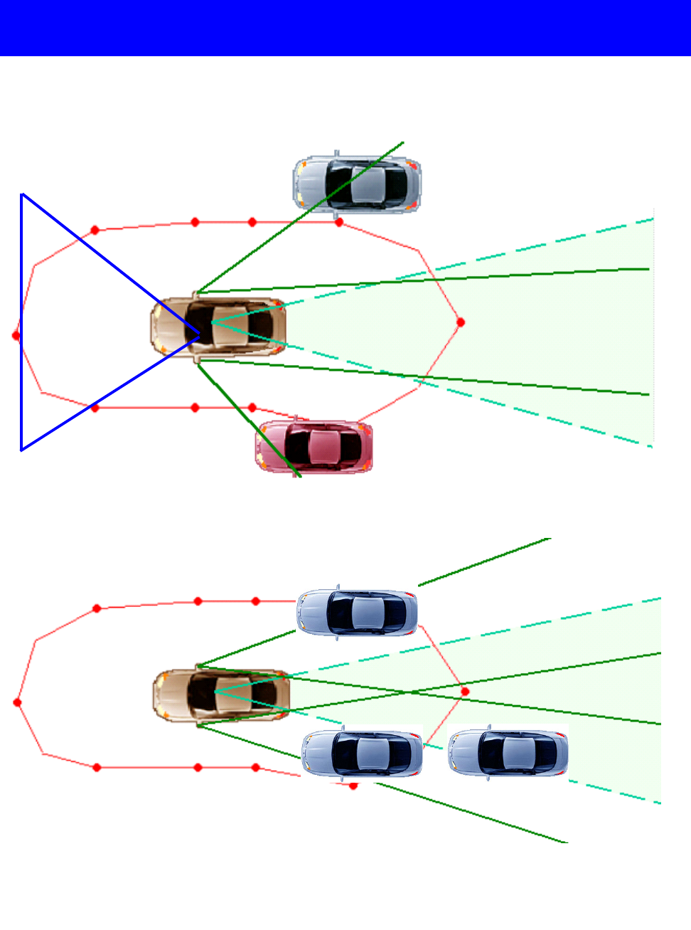
Vehicle Space Demonstration
Diagram 3— Blind Zone and Glare Elimination (BGE) Mirror Settings
Central
And Focal
Vision
Areas
Peripheral Vision
Area
Peripheral Vision
Area
Contemporary Setting
Left Side View
Contemporary Setting
Right Side View
Central
Space
Area
Inside
Rear
Mirror
View
Area
Module Two—August, 2001 Page 46
Module Two—August, 2001 Page 47
Notes

Knowledge and Skills
The student is expected to understand standard vehicle reference points.
Activities & Resources
Provide Worksheet W-2.8 “Standard Vehicle Reference Points”
as a class activity and topic assessment.
Topic: 5 Lesson: 2
Standard Vehicle Reference Points
Use Transparency T-2.36 “Standard Referencing Points” to
discuss techniques for establishing reference points from the
roadway to the vehicle.
T-2.36
Standard Referencing Points
“Reference Points” (IDS) may also be used to introduce or
review reference point skills. The video supplements the
information presented in this segment.
Module Two—August, 2001 Page 48

T-2.38 Front Limitation
T-2.39 Front Limitation
Topic: 5 Lesson: 2
...continued
Use Transparencies T-2.37, T-2.38, and T-2.39 “Front Limitation”
to discuss establishing front reference points.
• Intersections
•
Stopping position
• Perpendicular parking
• Placing front of vehicle even with a line or curb (The curb or
line should appear to run into the right side comer post or
under the left side mirror.)
T-2.37 Front Limitation
Module Two—August, 2001 Page 49

Topic: 5 Lesson: 2
...continued
T-2.41 Rear Limitation
T-2.42 Rear Limitation
Use Transparency T-2.40, T-2.41, and T-2.42 “Rear Limitation”
to discuss establishing rear reference points.
•
Backing position
•
Perpendicular parking
• Placing back bumper of vehicle so it is lined up with any rear
line or curb
T-2.40 Rear Limitation
Module Two—August, 2001 Page 50

Use Transparency T-2.45 and T-2.46 “Left Side Limitation” to
discuss establishing reference points for left side limitation.
•
Lane position 2
• Curb parking to left side
Topic: 5 Lesson: 2
...continued
T-2.45 Left Side Limitation
Use Transparency T-2.43 and T-2.44 “Right Side Limitation” to
discuss establishing reference points for right side limitation.
•
Lane position 3
•
Curb parking to right side
• Parking close to a white line, curb, or straight line to the
right side of the vehicle being driven; the center line of
the hood appears to be next to the line or curb (T-2.43)
• Parking close to a white line, curb or straight line to the
right side of the vehicle being driven; the center line of
the hood appears to be next to the line or curb (T-2.44)
•
Placing the right side of the vehicle three feet from a
white line or the curb (T-2.44)
• Placing the right side of the vehicle six feet away from a
line or curb (T-2.44)
T-2.43 Right Side Limitation
T-2.44 Right Side Limitation
T-2.46 Left Side Limitation
Module Two—August, 2001 Page 51

Topic: 5 Lesson: 2
...continued
Support Information
Standard Vehicle Reference Points
Definition of Reference Points
From the driver’s seat, see some part of the vehicle as it relates to some part of the roadway, to know where
the vehicle is actually located.
Reference Point Usage
Drivers cannot see the actual position of the car in relation to the roadway. The reason for this is that the
driver’s view of the road is blocked by the dashboard and by the hood of the car. Reference points can be
developed to serve as a guide to overcome the vision problems a driver encounters. Note: Reference points
are drawn on Transparencies T-2.36 and T-2.37.
The reference point to tell where the right tires are located is the hood ornament. If the car doesn’t have a
hood ornament, the curb would appear to be at the center of the hood. When the front of the car is even with
a line, the driver will see that line appear near the passenger’s side mirror. When the car is 3-6 inches away
from a line to the left, the driver will see that line appears to be one foot in from the edge of the left fender.
Standard Reference Points
The reference points presented show the way most drivers will see them. They are our “standard” reference
points. When attempting to discover a reference point, first use the “standard” reference point. If the
“standard” reference point was accurate for you, continue to use it. If any "standard" reference point does not
work for you, make note of your “personal” reference point. It won’t be more than a few inches away from the
“standard” reference point. Once you succeed, remember the correct picture of your “personal” reference
point for future use.
Reference points are the tools necessary for the driver to receive accurate feedback for successful
performance. If a driver parks alongside a curb perfectly but didn’t use reference points, there was no
learning of what gave the perfect results. It would be difficult to repeat the same actions with the same
results.
Use Transparency T-2.47 “Angle Parking” to discuss setup and
entry reference points for angle parking.
• Position 5 feet from lines
• Using right front turn point while targeting middle of lane
T-2.47 Angle Parking
Module Two—August, 2001 Page 52
Module Two—August, 2001 Page 53
Notes

Use Transparency T-2.50 “Lane Position # 2” to discuss
establishing reference points for left side lane limitation.
•
Left side of the lane
•
0-6 inches from the left side line
Topic: 5 Lesson: 3
Standard Vehicle Reference Points
T-2.50 Lane Position # 2
Use Transparencies T-2.48 and T-2.49 “Lane Position #1” to
discuss establishing reference points for the center of lane
position.
• Center of lane
• Three feet from left side
•
Three feet from right side
The driver is able to avoid a path of travel (POT) or a line of sight
(LOS) restriction or problem to the left side of lane. (T-2.48)
The driver is able to avoid a path of travel (POT) or a line of sight
(LOS) restriction or problem to the right side of lane. (T-2.49)
T-2.48 Lane Position #1
Knowledge and Skills
The student is expected to describe the placement options in a traffic lane utilizing visual reference
points.
Activities & Resources
T-2.49 Lane Position #1
Module Two—August, 2001 Page 54

Use Transparency T-2.52 and T-2.53 “Lane Position # 3” to
discuss establishing reference points for right side lane
limitation.
•
Right side of lane
• 0-6 Inches from right edge line
The driver is able to avoid a path of travel (POT) or a line of
sight (LOS) restriction or problem to the right side of the lane
by positioning over the yellow or white line to the left. (T-2.53)
Topic: 5 Lesson: 3
...continued
T-2.52 Lane Position #3
T-2.53 Lane Position # 3
Use Transparency T-2.51 “Lane Position #2” to continue
discussing the establishment of reference points for left side
lane limitation.
The driver is able to avoid a path of travel (POT) or line of sight
(LOS) restriction or problem to the left side of the lane by
positioning over the white line to the right.
T-2.51 Lane Position #2
Use Transparency T-2.54 “Lane Positions” to discuss
establishing lane positions from Lane Position # 1 to Lane
Position # 2 to avoid a path of travel or line of sight restriction.
Ask students to identify when this position adjustment would be
used.
T-2.54 Lane Positions
Module Two—August, 2001 Page 55

Use Transparency T-2.55 “Lane Positions” to discuss
establishing lane positions from Lane Position # 1 to Lane
Position # 3 to avoid a path of travel or line of sight restriction.
Ask students to identify when this position adjustment would be
used.
Topic: 5 Lesson: 3
...continued
Use Transparency T-2.56 “Possible Lane Positions” to discuss
establishing lane positions from Lane Position # 1 to Lane
Position # 2, 4 or 3, 5, to avoid a path of travel or line of sight
restriction. Ask students to identify when these position
adjustments would be used.
T-2.55 Lane Positions
T-2.56 Possible Lane Positions
“Reference Points” (IDS) may also be used to introduce or
review reference point skills. The video supplements the
information presented in this segment.
Use Transparency T-2.57 “Standard Referencing Points” to
review standard vehicle reference points for gaining good lane
position and placement.
T-2.57
Standard Referencing Points
Module Two—August, 2001 Page 56

Topic: 5 Lesson: 3
Support Information
Lane Position Options
With the use of reference points you can accurately position your vehicle within a lane to gain best space
management. There are five choices for lane position without making a lane change. Transparency T-
2.37 shows the three most frequently used lane positions. The fourth and fifth positions—which require
straddling the lane line to the left (LP4) or to the right (LP5)—are only used sparingly to momentarily control
two lanes.
Most cars are less than six feet wide; the highway lanes are commonly twelve feet wide. That gives you six
feet of empty space to the side without leaving the lane. There is enough room in most lanes to fit two cars.
• Lane Position #1 is where the car is centered within the travel lane.
• Lane Position #2
is where the car is 3-6 inches away from the left line of the travel lane.
• Lane Position #3 is where the car is 3-6 inches away from the right line of the travel lane. (Special
LP3 - When there is no lane line, Lane Position #3 is at least three feet away from the curb or from the
shoulder of the road.)
Module Two—August, 2001 Page 57
Module Two—August, 2001 Page 58
Notes

Module Two
Worksheets
W-2.1 Driver Preparations
W-2.2 Under the Hood Checks
W-2.3 Control and Information Devices
W-2.4 Control, Information, Comfort, and Safety Devices
W-2.5 Family Vehicle Instrument Panel
W-2.6 Family Vehicle Equipment
W-2.7 Vehicle Balance Basics
W-2.8 Standard Vehicle Reference Points
Simulation
SLS-2.1 Simulation Laboratory Session
Assessment
MA-2.1 Module Two Assessment
Virginia Department of Education
in cooperation with the
Virginia Department of Motor Vehicles
Module Two—August, 2001 Page 59
Curriculum Scope and Sequence Modules
for Driver Education in Virginia
Module Two—August, 2001 Page 60

Worksheet W-2.1
Driver Preparations
List the pre-drive, driver readiness, starting, and securing tasks used when preparing to drive.
Pre-drive Tasks Driver Readiness Tasks
• •
• •
• •
• •
• •
• •
• •
• •
• •
• •
Starting Tasks Securing Tasks
• •
• •
• •
• •
• •
• •
• •
• •
• •
• •
The driver education instructor may list tasks that are specific to the local program needs.
For instance, the program may have a standard shift vehicle for use in program.
Module Two—August, 2001 Page 61

Worksheet W-2.2
Under the Hood Checks
Module Two—August, 2001 Page 62
Using the picture with numbered lines leading to points on the engine, identify the items by writing
the corresponding number.
_____ Windshield Washer Fluid Reservoir
_____ Drive Belts
_____ Engine Oil Filler Cap
_____ Engine Coolant Reservoir
_____ Brake Fluid Reservoir
_____ Transmission Fluid Dipstick (Automatic Transmission)
_____ Engine Oil Dipstick
_____ Power Steering Fluid Reservoir
_____ Air Filter Assembly
_____ Battery
_____ Clutch Fluid Reservoir (Manual Transmission)
The items listed should be checked regularly to assure safe operation and to protect the engine.

Module Two—August, 2001 Page 63
Worksheet W-2.3
Control and Information Devices
Fill in the alert symbols, warning symbols, and control devices found on Transparencies
T-2.11 and T-2.12 as a classroom activity
A. _____________
B. _____________
C. _____________
D. _____________
E. _____________
F. _____________
G. _____________
H. _____________
I. _____________
J. _____________
K. _____________
L. _____________
M.
_____________
N. _____________
O. _____________
P. _____________
Q. _____________
R. _____________
S. _____________
T. _____________
U. _____________
V. _____________
W. _____________
X. _____________
Y. _____________
Z. _____________
AA. _____________
BB. _____________
CC. _____________
DD. _____________
EE. _____________
FF. _____________
GG. _____________
HH. _____________
II. _____________
JJ. _____________
KK. _____________
LL. _____________
MM. _____________

Worksheet W-2.4
Control, Information, Comfort, and Safety Devices
Label the Control and Information Devices as directed by the instructor during classroom
discussion.
Left Control Panel
01. ________________________
02. ________________________
03. ________________________
04. ________________________
Functional Levers
05. ________________________
06. ________________________
07. ________________________
08. ________________________
Passive Restraint
09. ________________________
Left Instrument Cluster
10. ________________________
11. ________________________
12. ________________________
13. ________________________
14. ________________________
15. ________________________
16. ________________________
17. ________________________
18. ________________________
19. ________________________
Center Instrument Cluster
20. ________________________
21. ________________________
22. ________________________
23. ________________________
24. ________________________
25. ________________________
Right Instrument Cluster
26. ________________________
27. ________________________
28. ________________________
29. ________________________
30. ________________________
31. ________________________
32. ________________________
33. ________________________
34. ________________________
35. ________________________
36. ________________________
37. ________________________
Auxiliary Panel Controls
38. ________________________
39. ________________________
40. ________________________
41. ________________________
42. ________________________
43. ________________________
44. __________________________
Module Two—August, 2001 Page 64

Worksheet W-2.5
Family Vehicle Instrument Panel
Module Two—August, 2001 Page 65
Identify the instruments and gauges on the instrument panel of your family car or that of a friend
and list them below.
A. ______________________ N. ______________________
B. ______________________ O. ______________________
C. ______________________ P. ______________________
D. ______________________ Q. ______________________
E. ______________________ R. ______________________
F. ______________________ S. ______________________
G. ______________________ T. ______________________
H. ______________________ U. ______________________
I. ______________________ V. ______________________
J. ______________________ W. ______________________
K. ______________________ X. ______________________
L. ______________________ Y. ______________________
M. ______________________ Z. ______________________
Now draw the instrument panel on the rear side of this sheet and use the image below as a guide
to label the instruments and gauges on your drawing.

Worksheet W-2.6
Family Vehicle Equipment
Use this worksheet to determine whether your family vehicle or that of a friend is equipped
with the following safety, communication, comfort, and convenience devices and if so
equipped, where the control levers, switches, or buttons are located.
Equipped Yes/No Location of control lever or switch
Tilt steering wheel _______ ____________________________
Automatic Transmission _______ ____________________________
Manual Transmission _______ ____________________________
Parking Brake _______ ____________________________
Cruise Control _______ ____________________________
Mirror Controls _______ ____________________________
Hazard Flasher _______ ____________________________
Headlights _______ ____________________________
Instrument Panel Light Switch _______ ____________________________
Hood Release _______ ____________________________
Trunk Release _______ ____________________________
Seat Control Manual _______ ____________________________
Seat Control Electric _______ ____________________________
Separate Turn Indicator Lever _______ ____________________________
Windshield Wiper Switch _______ ____________________________
Windshield Washer Switch _______ ____________________________
Air Bag Cut Off Switch _______ ____________________________
Electric Door Locks _______ ____________________________
Childproof Rear Door Locks _______ ____________________________
Module Two—August, 2001 Page 66
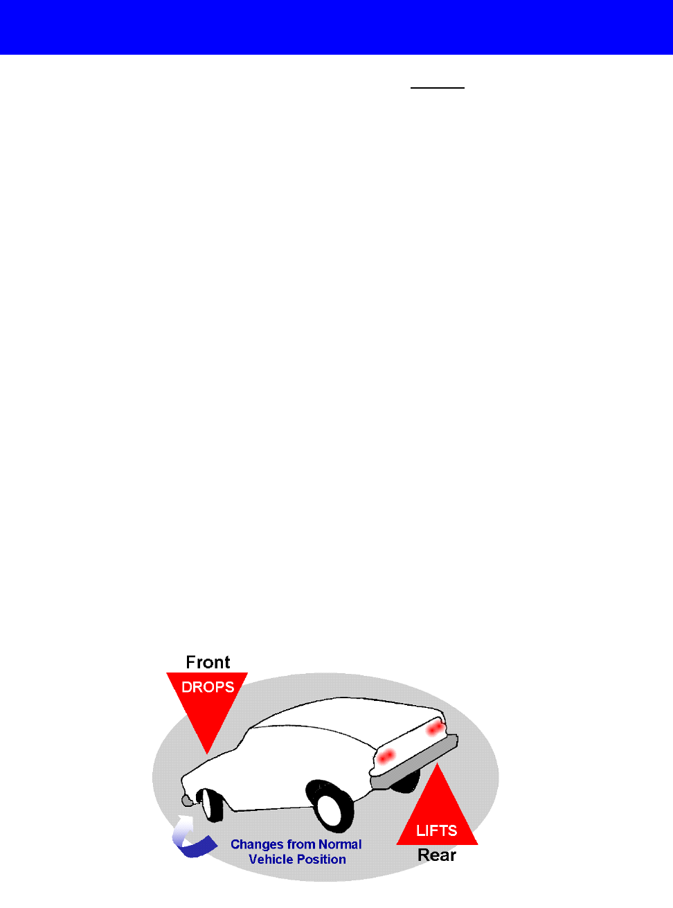
Worksheet W-2.7
Vehicle Balance Basics
Complete the following questions during the discussion ABOUT vehicle balance:
1. Define vehicle balance: ________________________________________________________
___________________________________________________________________________
___________________________________________________________________________
___________________________________________________________________________
2. If a driver brakes too hard, the vehicle weight shifts to the _____________________________.
3. If a driver accelerates too hard, the vehicle weight shifts to the _________________________.
4. If a driver steers too quickly to the right, the vehicle weight shifts to the __________________.
5. If a driver steers too quickly to the left, the vehicle weight shifts to the ___________________.
6. Explain how seating position may affect the balance of your vehicle: _____________________
___________________________________________________________________________
___________________________________________________________________________
___________________________________________________________________________
7. What is the problem shown by the vehicle below? ___________________________________
___________________________________________________________________________
___________________________________________________________________________
___________________________________________________________________________
Module Two—August, 2001 Page 67

Draw the standard reference points onto the vehicles below as requested:
Front Limitation
0-6 inches from the right
2-3 feet from the right
5-8 feet from the right
Worksheet W-2.8
Standard Vehicle Reference Points
Module Two—August, 2001 Page 68

Draw the standard reference points onto the vehicles below as requested:
Rear Limitation
0-6 inches from the left
2-3 feet from the left
5-8 feet from the left
Worksheet W-2.8
...continued
Module Two—August, 2001 Page 69

SLS-2.1
Simulation Laboratory Session
Suggested Titles: “Standing Out Right” (DORON Video or Laserdisc)
“Ins and Outs of Turns” (DORON Video or Laserdisc)
“Controlling Your Vehicle” (SSI Safe Driver Training Series)
“Turning and Parking Maneuvers” (SSI Safe Driver Training Series)
Learning Goals: The student demonstrates comprehension of pre-drive, driver readiness,
start, securing, and vehicle positioning in lane which will increase student’s
ability to position vehicle for basic vehicle maneuvers.
Performance: Performances are based on the simulation video used for this section. It is
recommended to start with a session that demonstrates the use of the
simulator and establishes the need for procedures and good seating
position. Explain the need for holding the wheel at a position that is below
the center of the wheel due to airbag displacement. Demonstrate the correct
seating and steering positions for vehicle control.
Assessment: Instructor records assessment of speed, positioning, and techniques on the
district on-street records form. Student assessment of simulation activities
may also be added to the student portfolio.
Instructor Activities Student Driver
Activities
Materials Needed and Notes
Module Two—August, 2001 Page 70

Module Assessment MA-2.1
Module Two Assessment
Select the best answer and place the appropriate letter (A, B, C, D, or E) on the answer sheet
provided
.
1. What should a driver look for when checking around the outside of a vehicle?
A. Broken glass on vehicle.
B. Tire condition.
C. Fluid leaks.
D. Debris on ground.
E. All of the above.
2. Where should valuables be stored to avoid potential problems?
A. Right front floor board.
B. Rear seat.
C. Trunk.
D. Glove compartment.
E. All of the above.
3. When parked at a curb, from which direction should the driver approach the vehicle?
A. From the rear.
B. From the front.
C. From the left side.
D. From the right side.
E. None of the above.
4. When establishing a seating position, the driver should adjust for __________.
A. driver foot pedal position
B. driver hand position
C. driver dead pedal position
D. driver visual needs
E. all of the above
5. When starting the vehicle, what should be the first task?
A. Place foot on brake.
B. Place the gear selector in (P)ark or (N)eutral.
C. Place the key in the ignition.
D. Check or set the parking brake.
E. None of the above.
6. When securing the vehicle, what should be the first task?
A. Set the parking brake.
B. Park in a legal, secure parking space.
C. Place the gear selector in (P)ark.
D. Turn off any accessories.
E. None of the above.
7. When properly seated, the top of the steering wheel should be __________.
A. no higher than the top of your shoulders
B. no higher than your chin
C. no higher than your ears
D. no higher than the point at which you feel comfortable
E. none of the above
8. The purpose of the parking brake is to __________.
A. stop your vehicle on a slick surface
B. stop your vehicle on in an emergency
C. hold the vehicle in place when parked
D. hold the vehicle only when parked on a hill
E. all of the above.
9. Which of the following symbols represents a safety belt reminder or warning?
E. None of these.
Module Two—August, 2001 Page 71

Module Assessment MA-2.1
...continued
10. Which of the following symbols represent windshield defrosters?
E. None of these.
11. Which of the following symbols represent headlamp beam switch?
E. None of these.
12. Which of the following
symbols represent oil pressure warning?
E. None of these.
13. Pulling or pushing the lights lever will __________.
A. flash brake lights and turn signals
B. turn on head lights and parking lights
C. change to or from high to low beam
D. dim dashboard high intensity
E. all of these
14. What reference point is illustrated here?
A. Front alignment.
B. Rear alignment.
C. 6 inches from side curb.
D. Angle parking.
E. None of these.
15. A vehicle that is in a balanced state __________.
A. has more weight concentrated on the front tire patches while stopping
B. has more weight concentrated on the rear tire patches while accelerating
C. has weight concentrated over the four tire patches while stopped
D. has more weight shifted to the left or right front tire patch while turning
E. none of the above
16. Weight can be shifted to the front tire patches of the vehicle by __________.
A. covering accelerator
B. acceleration
C. releasing the brake
D. controlled braking
E. all of the above
17. The oil pressure light comes on when the vehicle is moving on the highway.
What does it mean?
A. The oil filter should be changed.
B. The oil pressure is low.
C. The oil needs to be changed.
D. It has defective warning light.
E. None of the above.
18. Hard brake application together with sharp steering input to the left results in __________.
A. major weight shift to the front tire patches
B. major weight shift to the left front tire patch
C. major weight shift to right front tire patch
D. major weight shift from the right rear tire patch
E. none of the above
Module Two—August, 2001 Page 72

Module Assessment MA-2.1
...continued
19. What reference point is illustrated here?
A. Front alignment.
B. Rear alignment.
C. 6 inches from side curb.
D. Angle parking.
E. None of these.
20. Changes in automotive design without appropriate adjustment on the part of drivers that appear
to contribute to off road crashes are __________.
A. seat and steering wheel height
B. improved brakes and reduced lock to lock turns in steering
C. improved brakes and headlights
D. reduced lock to lock turns in steering and improved headlights
E. all of the above
21. What lane position is illustrated here?
A. Lane position one.
B. Lane position two.
C. Lane position three.
D. Lane position four.
E. None of these.
22. What lane position is illustrated here?
A. Lane position one.
B. Lane position two.
C. Lane position three.
D. Lane position four.
E. None of these.
23. Effective targeting allows the driver to __________.
A. visualize the space they intend to occupy
B. begin learning to use a searching process
C. look far ahead
D. plan ahead
E. all of the above
24. What lane position is illustrated here?
A. Lane position one.
B. Lane position two.
C. Lane position three.
D. Lane position four.
E. None of these.
25. What reference point is illustrated here?
A. Front alignment.
B. Rear alignment.
C. 6 inches from side curb.
D. 2-3 feet from right.
E. None of these.
Module Two—August, 2001 Page 73

Module 2 Assessment Answer Sheet
Name: _________________________________
Date: _________________________________
Score: _________________________________
1. _____ 14. _____
2. _____ 15. _____
3. _____ 16. _____
4. _____ 17. _____
5. _____ 18. _____
6. _____ 19. _____
7. _____ 20. _____
8. _____ 21. _____
9. _____ 22. _____
10. _____ 23. _____
11. _____ 24. _____
12. _____ 25. _____
13. _____
Module Two—August, 2001 Page 74

Module 2 Assessment Answer Key
Name: ASSESSMENT ANSWER SHEET
Date: _________________________________________________
Score:
4 POINTS FOR EACH CORRECT ANSWER BELOW
1. E
2. C
3. B
4. E
5. D
6. B
7. B
8. C
9. C
10. D
11. B
12. D
13. C
14. C
15. C
16. D
17. B
18. C
19. A
20. B
21. B
22. A
23. E
24. C
25. D
Module Two—August, 2001 Page 75
