IMPORTANT Read this instruction manual. Failure to follow the instructions in this manual can result
in damage to the unit, injury to operating personnel, and poor equipment performance.
CAUTION All internal adjustments and maintenance must be performed by qualified service personnel.
Material in this manual is for informational purposes only. The contents and the product it describes are
subject to change without notice. Thermo Fisher Scientific makes no representations or warranties with
respect to this manual. In no event shall Thermo be held liable for any damages, direct or incidental,
arising from or related to the use of this manual.
© 2019 Thermo Fisher Scientific Inc. All rights reserved.
Contents
Contents
Models .......................................................................................1
Safety Precautions....................................................................2
Unpacking.................................................................................4
Packing List ..............................................................................5
General Recommendations .....................................................6
Temperature Monitoring ...................................................... 6
General Usage ...................................................................... 6
Initial Loading...................................................................... 6
Battery Door Opening / Closing .......................................... 7
Operating Standards ...............................................................8
Electrical Specifications....................................................... 8
Installation................................................................................9
Location ............................................................................... 9
Wiring .................................................................................. 9
Leveling ............................................................................. 10
Backup System (Optional) ................................................. 10
Super Insulated Cabinet Construction................................ 10
Door Operation .................................................................. 10
Pressure Equalization Port ................................................. 12
Installing the Remote Alarm Connector ............................ 12
Intended Use ...................................................................... 13
Start Up...................................................................................14
Connectivity Requirements................................................ 14
Initial Start Up.................................................................... 16
Standby Mode .................................................................... 29
Operation................................................................................30
Operation Overview........................................................... 30
Home Screen ...................................................................... 30
Settings............................................................................... 31
Event Log........................................................................... 43
Alarms................................................................................ 45
Users................................................................................... 45
Reports ............................................................................... 48
Chart................................................................................... 49
Health Status and Alarm Management ...............................53
Health Status Overview ..................................................... 53
Notifications / Cautions ..................................................... 55
Alarms / Warning............................................................... 57
Contents
Backup System (Optional) ....................................................58
CO2 and LN2 Precautions ................................................. 58
Installation.......................................................................... 59
Start Up .............................................................................. 60
Operation............................................................................ 60
Chart Recorders (Optional)..................................................61
Set Up and Operation......................................................... 61
Changing Chart Paper ........................................................ 62
Calibration Adjustment ...................................................... 62
Maintenance and Troubleshooting.......................................63
Cleaning the Condenser ..................................................... 63
Cleaning the Condenser Filter............................................ 63
Gasket Maintenance........................................................... 63
Defrosting the Freezer........................................................ 64
Battery Maintenance .......................................................... 64
Maintenance Schedule ....................................................... 65
Troubleshooting Guide..........................................................66
ConnectivityTroubleshooting ...............................................70
Warranty ................................................................................72
Warranty (International) ......................................................73
Appendix A: Alarm Summary .................................................74
Appendix B: Event Log Detail .................................................81
Appendix C: City Time Zone ...................................................83

Models
Thermo Fisher Scientific Ultra Low Temperature Installation and Operation 1
1 Models
* Note: Energy Star is not applicable to the G and V models.
Brand - Model Size (xxx) Voltage (*)
Thermo Scientific – TSXxxx86* 400 / 500 / 600 / 700 A / D / V / G

Safety Precautions
2 Installation and Operation Thermo Fisher Scientific Ultra Low Temperature
2 Safety Precautions In this manual, the following symbols and conventions are used:
This symbol used alone indicates important operating instructions which
reduce the risk of injury or poor performance of the unit.
CAUTION: This symbol, in the context of a CAUTION, indicates a
potentially hazardous situation which if not avoided could result in minor to
moderate injury or damage to the equipment.
WARNING: This symbol indicates potentially hazardous situations which,
if not avoided, could result in serious injury or death.
WARNING: This symbol indicates situations where dangerous voltages
exist and potential for electrical shock is present.
The snowflake symbol indicates extreme low temperatures and high risk of
frostbite. Do not touch bare metal or samples with unprotected body parts.
This symbol indicates a need to use gloves during the indicated procedures.
If performing decontamination procedures, use chemically resistant gloves.
Use insulated gloves for handling samples and when using liquid nitrogen.
Before installing, using or maintaining this product, please be sure to read
this manual and product warning labels carefully. Failure to follow these
instructions may cause this product to malfunction, which could result in
injury or damage.

Safety Precautions
Thermo Fisher Scientific Ultra Low Temperature Installation and Operation 3
Below are important safety precautions that apply to this product:
Use this product only in the way described in the product literature and in
this manual. Before using it, verify that this product is suitable for its
intended use. If this equipment is used in a manner not specified by the
manufacturer, the protection provided by the equipment may be impaired.
Do not modify system components, especially the controller. Use OEM
exact replacement equipment or parts. Before use, confirm that the product
has not been altered in any way.
WARNING: Your unit must be properly grounded in conformity with
national and local electrical codes. Never connect the unit to overloaded
power sources.
WARNING: Disconnect the unit from all power sources before cleaning,
troubleshooting, or performing other maintenance on the product or its
controls.
WARNING: “Caution, risk of fire”. This unit is charged with hydrocarbon
refrigerants.
Unpacking
4 Installation and Operation Thermo Fisher Scientific Ultra Low Temperature
3 Unpacking At delivery, examine the exterior for physical damage while the carrier’s
representative is present. If exterior damage is present, carefully unpack and
inspect the unit and all accessories for damage.
If there is no exterior damage, unpack and inspect the equipment within five
days of delivery. If you find any damage, keep the packing materials and
immediately report the damage to the carrier. Do not return goods to the
manufacturer without written authorization. When submitting a claim for
shipping damage, request that the carrier inspect the shipping container and
equipment.
Packing List
Thermo Fisher Scientific Ultra Low Temperature Installation and Operation 5
4 Packing List Inside the freezer cabinet is a bag containing:
• This manual
• A handle lock key
• USB drive with user’s manuals, including translated versions
• Certificates of conformance and calibration
• A remote alarm contact connector
• Posts for rear spacing
If you have ordered a field-installed chart recorder, the bag will also contain:
• Recorder installation instructions
• Extra inkless paper
If you have ordered a backup system, the cabinet will also contain:
• A hose assembly
• English and metric connectors
If specified on the order, the bag may also include:
• A QC temperature graph and test log
• Calibration information
If you have ordered the Proximity Access Card Option, the cards will be in a
bag attached to the front of the freezer.

General Recommendations
6 Installation and Operation Thermo Fisher Scientific Ultra Low Temperature
5 General
Recommendations
5.1 Temperature
Monitoring
IMPORTANT NOTE:We recommend the use of a redundant and
independent temperature monitoring system so that the freezer can be
monitored continuously for performance commensurate with the value of
product stored.
5.2 General Usage This refrigeration system is designed to maintain ultra-low temperatures
with safety in an ambient environment within 15°C to 32°C (59°F to 90°F),
only when the freezer is used for storage. For TSX 700 models, the
maximum operating environment is 28°C (83°F).
WARNING: This unit is not a “rapid-freeze” device. Freezing large
quantities of liquid, or high-water content items, will temporarily increase
the chamber temperature and will cause the compressors to operate for a
prolonged time period.
Avoid opening the door for extended time periods since chamber
temperature air will escape rapidly. Also, keep the inner doors closed as
much as possible. When room air, which is higher in humidity, replaces
chamber air, frost may develop in the chamber more rapidly.
5.3 Initial Loading Allow the freezer to operate at the desired temperature for a minimum
of 12 hours before loading.
Load the freezer one shelf at a time, beginning with the top shelf. After
loading each shelf, allow the freezer to recover to the desired set point before
loading the next shelf. Repeat this process until the freezer is fully loaded.
CAUTION: Failure to follow these procedures or overloading the unit may
cause undue stress on the compressors or jeopardize user product safety.

General Recommendations
Thermo Fisher Scientific Ultra Low Temperature Installation and Operation 7
5.4 Battery Door
Opening / Closing
To open the grille door, pull the door from the top right corner as shown in
the figure below.
To close the grille door, push the door against frame to hold latch in
position.
Figure 1. Door Opening

Operating Standards
8 Installation and Operation Thermo Fisher Scientific Ultra Low Temperature
6 Operating
Standards
The freezers described in this manual are classified for use as stationary
equipment in a Pollution Degree 2 and Over voltage Category II
environment.
These units are designed to operate under the following environmental
conditions:
• Indoor use
• Altitude up to 2000 m
• Maximum relative humidity 60% for temperatures within 15°C to 32°C
(59°F to 90°F). For TSX 700 models, the maximum operating
environment is 28°C (83°F).
• Main supply voltage fluctuations not to exceed ±10% of the nominal
voltage.
• For the TSX series, the ULT should not be connected to a GFCI
(Ground Fault Circuit Interrupter) protected outlet as it may be subject
to nuisance tripping.
6.1 Electrical
Specifications
The last character in the model number listed on the dataplate identifies the
electrical specifications for your unit.
Specific unit current rating is listed on
the dataplate.
The voltage types are A, D, V and G as specified in the following table:
Table 1. TSX Series Electrical Specifications
Model Voltage Frequency Current
400D/V 208-230 V 50/60 Hz 4.0 A
400A 115 V 60 Hz 9.0 A
400G 100 V 50/60 Hz 10.5 A
500D 208-230 V 60 Hz 5.1 A
500V 208-230 V 50 Hz 5.2 A
500A 115 V 60 Hz 9.5 A
500G 100 V 50/60 Hz 9.5 A
600D/V 208-230 V 50/60 Hz 4.0 A
600A 115 V 60 Hz 8.5 A
600G 100 V 50/60 Hz 9.5 A
700D 208-230 V 60 Hz 5.8 A
700V 208-230 V 50 Hz 6.1 A
700A 115 V 60 Hz 10.6 A

Installation
Thermo Fisher Scientific Ultra Low Temperature Installation and Operation 9
7 Installation
WARNING: Do not exceed the electrical rating printed on the data plate
located on the lower left side of the unit.
7.1 Location Install the unit in a level area free from vibration with a minimum of 8 inch
(20 cm) of space on the top and sides, 6 inch (15 cm) in back. Refer to
Section 7.3 for further instructions on leveling cabinets. Allow enough
clearance so that door can swing open at least 85°.
The rear spacing posts provided with the freezer can be used to ensure
proper clearance. To install the spacing posts, screw them into the back in
the rear deck area.
Do not position the equipment in direct sunlight or near heating diffusers,
radiators, or other sources of heat. The ambient temperature range at the
location must be 15°C to 32°C (59°F to 90°F). For TSX 700 models, the
maximum operating environment is 28°C (83°F).
7.2 Wiring
CAUTION: Connect the equipment to the correct power source. Incorrect
voltage can result in severe damage to the equipment.
CAUTION: For personal safety and trouble-free operation, this unit must
be properly grounded before it is used. Failure to ground the equipment
may cause personal injury or damage to the equipment. Always conform to
the National Electrical Code and local codes. Do not connect the unit to
overloaded power lines.
CAUTION: Do not position the unit in a way that impedes access to the
disconnecting device or circuit breaker in the back of the unit.
CAUTION: Always connect the freezer to a dedicated (separate) circuit.
Each freezer is equipped with a service cord and plug designed to connect it
to a power outlet which delivers the correct voltage. Supply voltage must be
within ±10% of the freezer rated voltage.
CAUTION: Never remove or disable the grounding prong from the service
cord plug. If the prong is removed, the warranty is invalidated.

Installation
10 Installation and Operation Thermo Fisher Scientific Ultra Low Temperature
7.3 Leveling Make sure that the floor is level. The unit must be level both front to back
and side to side.
400 box capacity models are equipped with one leveling leg on the right
hand side. These may be used to help prevent the unit from shifting during
a door opening.
Be certain to lock the brakes for units equipped with casters.
7.4 Backup System
(Optional)
If you are using a CO
2
or LN
2
backup system, refer to Section 11 for
installation and operation instructions.
7.5 Super Insulated
Cabinet Construction
In all models, the cabinet walls have a vacuum insulation core encapsulated
by a sealed film laminate.
CAUTION: Never drill holes in or near the cabinet walls. Drilling could
damage the insulation and make the unit inoperable.
7.6 Door Operation Upright freezer models are equipped with an advanced assembly specifically
designed for ultra-low temperature freezers.
Features include:
• One-hand operation
• A front-accessible lock
• Hasps for a standard padlock to provide additional security. Length of
the shackle must be between 3/4 inch (1.9 cm) and 1
1
/
2
inch (3.8 cm).
• Durable construction for reliable operation and safe product storage.
• Door ramp alignment feature
• Optional controlled access to the freezer with Proximity Access cards.
CAUTION: When moving the freezer, always grasp cabinet surfaces; never
pull the freezer by the latch handle.
7.6.1 Opening the Door For freezers with the Proximity Access Card option:
1. Remove the padlock if installed.
Installation
Thermo Fisher Scientific Ultra Low Temperature Installation and Operation 11
2. To unlock the door, pass the card in front of the freezer below the LCD
display.
3. Grasp the latch handle and pull it toward yourself until the latch
disengages from the cabinet strike.
4. Keep pulling by the latch handle to open the main door.
For freezers without the Access Card option:
1. Remove the padlock if installed.
2. Grasp the latch handle and pull it toward yourself until the latch
disengages from the cabinet strike.
3. Keep pulling by the latch handle to open the main door.
7.6.2 Opening the Door During
a Power Outage
In case of power outage and a unit that has the Proximity Access Card
option, you may use a 9 volt battery to activate the system. To access the
9 volt terminal, remove the USB cover and locate the battery terminals.
Once the terminals are exposed, open the door by holding the 9 volt battery
against the terminals and pass a valid proximity card below the display area.
Once the door is open, remove the 9 volt battery.
Note: The terminals are polarized therefore orient the 9 volt battery properly.
7.6.3 Closing the Door Note: The latch does not self-engage automatically when you close the door. You
must rotate the latch into the open position first.
1. Grasp the latch handle (preferably with your left hand) and pull it
toward yourself, rotating the latch into the open position.
2. Move the freezer door into the closed position and gently push the
handle away from you, making sure that the latch engages fully with the
cabinet strike.
3. Keep applying gentle pressure to the latch handle until the latch is
securely in closed position.
4. Insert the key and rotate counterclockwise to lock.
5. Replace the padlock as required.

Installation
12 Installation and Operation Thermo Fisher Scientific Ultra Low Temperature
7.7 Pressure
Equalization Port
When an upright ultra-low temperature freezer door is opened, room
temperature air rushes into the storage compartment. When the door is
closed, the fixed volume of air is cooled rapidly. Pressure drops below
atmospheric pressure, resulting in a substantial vacuum. Re-entry into the
cabinet is impossible until internal pressures are returned to atmospheric
pressure. Without a pressure equalization mechanism, it can take, in
extreme cases, several hours before the door can easily be reopened.
All upright models feature a port that provides vacuum relief after door
openings. The pressure equalization port is located in the door behind the
eye-level panel on the front of the freezer. Although the port is designed to
self-defrost, excessive frost accumulation on the inner door could eventually
restrict air flow. Therefore you should periodically inspect the inner door
and brush away any loose frost using a stiff nylon brush.
7.8 Installing the
Remote Alarm
Connector
The remote alarm contacts are located on the back of the freezer above and
to the left of the power switch. After installing the wiring from the remote
alarm to the connector, install the connector to the freezer micro-board.
The pin configuration is shown in Figure 2 below.
Figure 2. Remote Alarm Pin Configuration
The contacts will trip in the event of a power outage, high temperature
alarm, low temperature alarm or door ajar alarm.
Installation
Thermo Fisher Scientific Ultra Low Temperature Installation and Operation 13
7.9 Intended Use The –86°C freezer (refer to Section 1 for the specific model series) described
in this manual are high performance units for professional use. These
products are intended for use as cold storage in research use and as a general
purpose laboratory freezer, storing samples or inventory at operating
temperatures between –50°C and –80°C.
It is not considered a medical device and has therefore not been registered
with a medical device regulatory body (e.g. FDA): that is, it has not been
evaluated for the storage of samples for diagnostic use or for samples to be
re-introduced to the body.
This unit is not intended for use in classified hazardous locations, nor to be
used for the storage of flammable inventory.

Start Up
14 Installation and Operation Thermo Fisher Scientific Ultra Low Temperature
8 Start Up
8.1 Connectivity
Requirements
There are two requirements to take full advantage of your freezers
connectivity options:
1. The freezer will need to be connected to a wireless network with internet
connection, the freezer is only able to use a wireless connection.
a. Refer to WiFi Specification table in Section 8.1.1 for acceptable
network security parameters.
b. Please speak with your local Information Technology (IT) group
about the correct wireless network and password to use.
2. The individual monitoring the unit will need a Thermo Fisher Connect
account and will need to link the unit to his/her account via
InstrumentConnect™. To create a Thermo Fisher Connect account:
a. Use a web browser to open the following URL:
https://apps.thermofisher.com
b. Choose "Create an Account" and follow the instructions to establish
a new account. (Remember your login information for later use.)
c. (Optional) Download the InstrumentConnect mobile/tablet
application from the AppStore or PlayStore.
Note: InstrumentConnect™ is the section of Thermo Fisher Connect where all
connected instruments can be monitored. To access this section, click on the
InstrumentConnect icon indicated below.
Note: If you are a user in China, the web client allows you to switch to that
region after logging in or you can log in directly to the China environment by
using https://china.apps.thermofisher.com.

Start Up
Thermo Fisher Scientific Ultra Low Temperature Installation and Operation 15
8.1.1 Specifications
Note: Thermo Fisher Scientific connected devices do not support the use of proxy
servers or enterprise networks which require identity/username for internet
access.
8.1.2 In case of Failure If your freezer is unable to connect to either a wireless network or a cloud
account, please verify your name and password, and attempt to re-connect.
If issues persist, please contact Your Local Support.
Note: If your network password expires or changes, your freezer will no longer
connect automatically. Be sure to manually update your password in the freezer
user interface settings to reconnect. Failure to reconnect within 3 days will result
in data loss.
Table 2. Specifications
Parameter Specification
Default Wi-Fi transmission frequency to the cloud
Every 5 minutes for sensor
data transmission.
Real-time for alarm events
WiFi protocol
2.4 GHZ only: IEEE
802.11B, IEEE 802.11G,
IEEE 802.11N
Wi-Fi Security
WPA / WPA2PSK
WPA / WPA2EAP
PEAP
Proxy servers are not
supported.
Wi-Fi Data Rate Minimum of 1 Mbps
Wi-Fi Range Up to 30 meters
Minimum Required Wireless Signal -70 dbM
Firewall Ports that must open 80, 123, 443

Start Up
16 Installation and Operation Thermo Fisher Scientific Ultra Low Temperature
8.2 Initial Start Up To start up the freezer, complete the following steps:
1. Plug the freezer into the power outlet.
2. Turn the power switch in back of the freezer, on the bottom right, to the
ON position.
3. Once the freezer is powered up, the Thermo Scientific logo is displayed
on the front screen. If this is the first time the unit is being turned on, an
initial setup must be completed. Press the Start Setup button to initiate
the setup.
Figure 3. Main Screen
The first step of the setup is to select the language. This screen allows you to
specify the preferred display language. Once the language is selected, press
the Next button.
Figure 4. Language Selection Screen
The next screen allows you to select your location. Enter the name of the
city and select from the list of suggestions displayed.

Start Up
Thermo Fisher Scientific Ultra Low Temperature Installation and Operation 17
After selecting the region, press the Next button.
Figure 5. Region Setup Screen
When entering your “City” into Region Setup screen, refer to “Appendix C: City
Time Zone” . Follow the table to select the city closest to your time zone.
The next screen allows you to identify an individual freezer by specifying a
Unit Name. After entering a name, press the Next button.
Figure 6. Unit Name Setup Screen
The next few screens allow you to setup a wireless connection to store
information on InstrumentConnect.
To fully connect your new unit, you will need to:
1. Connect the unit to a wireless network allowing data to be sent to
Thermo Fisher Connect.
2. Log in to Thermo Fisher Connect (web or app) and link the unit to
your account via InstrumentConnect.

Start Up
18 Installation and Operation Thermo Fisher Scientific Ultra Low Temperature
Note: Before you begin, establish a Thermo Fisher Connect account and have
your network login information available. Refer to section Section 8.1 for
details.
The first screen requires acceptance of the terms and conditions of using
connectivity on this device.
If you chose to Skip this acceptance, Wi-Fi connectivity will be disabled.
You will be able to accept the terms and enable connectivity at a later time
via the Connectivity settings menu.
Figure 7. Terms and conditions screen
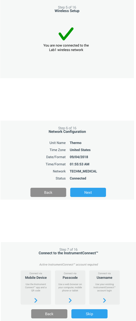
Select a wireless network and press the Next button.
Figure 8. Wireless Setup Screen
Once the intended network is selected (highlighted), you must press the
Next button.
Note: If you do not want to setup a wireless connection, press the Skip button.
The Date and Time Setup screens will appear. To setup a wireless connection
later, press the Settings menu icon and select Connectivity.

Start Up
Thermo Fisher Scientific Ultra Low Temperature Installation and Operation 19
Enter the network password and press the Next button.
Figure 9. Wireless Setup (Password) Screen
Note: Press the eye icon on the screen for password visibility
Note: The on-screen keyboard does not support all special characters. Please
inquire with your local IT group for assistance with password reset to
accommodate allowable character entry.
Figure 10. On Screen Key board

Start Up
20 Installation and Operation Thermo Fisher Scientific Ultra Low Temperature
Figure 11. On Screen Key-board
A success message is displayed once the connection is established. If the
connection fails, either due to an incorrect Wi-Fi password or network
unavailability, a general error message is displayed. After 5 seconds, the
interface will return to the previous screen.
If this occurs, check the network status and re-enter the correct password to
establish the connection. (Tip: use the eye icon to verify the password entry
before attempting connection.)
Refer to Section 15 for more connectivity troubleshooting.
Figure 12. Wireless Setup Error Message Screen
Start Up
Thermo Fisher Scientific Ultra Low Temperature Installation and Operation 21
Figure 13. Wireless Setup Success Message Screen
The Network Configuration screen appears after a successful connection is
established, which displays the time and date based on the wireless network.
Verify the information displayed and press the Next button.
Figure 14. Network Configuration Screen
The next screen displays three options to connect your unit to
InstrumentConnect. You can store historical data and receive alarm
notifications to your InstrumentConnect account.
Figure 15. Connect to the InstrumentConnect Screen

Start Up
22 Installation and Operation Thermo Fisher Scientific Ultra Low Temperature
Connect via Mobile Device
Selecting the Connect via Mobile Device option displays the following
screen. Follow the instructions to connect to InstrumentConnect.
Figure 16. Connect to the InstrumentConnect (via Mobile Device)
Screen and Mobile Device Screens
Connect via Passcode
This option displays a code that has to be entered to connect to
InstrumentConnect.
Figure 17. Connect to the InstrumentConnect (via Passcode) Screen

Start Up
Thermo Fisher Scientific Ultra Low Temperature Installation and Operation 23
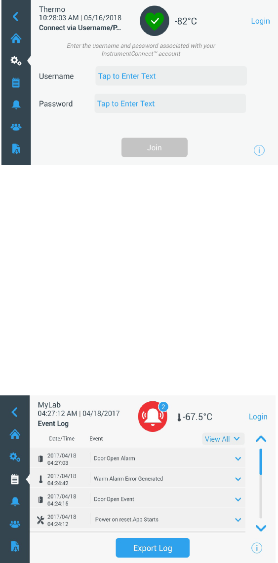
Connect via user name
Sign in using your InstrumentConnect user name and password and press
the Link Account button.
Figure 18. Connect to the InstrumentConnect (via user name) Screen
If the connection is successful via any of the three methods, a success
message is displayed.
Note: If a connection is established, and you choose to connect the unit with
additional user InstrumentConnect accounts, you can press the Back button and
repeat the same process. If you go back and then decide not to continue an
additional connection setup you will need to press the Skip button on the
connection screen (See Figure 15). This will not remove any established
connections previously created. You can also add additional connections via
the Connection Settings menu after initial start-up is complete.
If the connection is unsuccessful, an error message is displayed. After 5
seconds, the interface will return to the previous screen. Check the network
status and any entered passwords, etc. and repeat the previous steps to
establish a successful unit connection.
Refer to Section 15 for more connectivity troubleshooting.

Start Up
24 Installation and Operation Thermo Fisher Scientific Ultra Low Temperature
The next screen allows you to specify the temperature unit. After selecting
the unit, press the Next button.
Figure 19. Units Setup Screen
The next three screens provide installation instructions.
The first screen provides information regarding power source and ambient
temperature conditions. Press the Next button to continue through the
installation instructions.
Figure 20. Installation Instructions (Power and Temperature) Screen

Start Up
Thermo Fisher Scientific Ultra Low Temperature Installation and Operation 25
The second screen provides information regarding unit positioning, spacing
and leveling. Press the Next button after reviewing.
Figure 21. Installation Instructions (Positioning) Screen
The third screen provides information regarding initial freezer loading. Press
the Next button after reviewing.
Figure 22. Installation Instructions (Before Usage) Screen
The next screen allows you to specify the temperature, warm and cold alarm
setpoints. After setting the temperatures, press the Next button.
Figure 23. Setpoints and Alarms Screen

Start Up
26 Installation and Operation Thermo Fisher Scientific Ultra Low Temperature
This screen allows you to select the Operating Mode. Once the mode has
been selected, press the Next button.
Figure 24. Operating Mode Setup Screen
This screen allows you to specify the Access Mode.
Figure 25. Access Mode Setup Screen
If Secured Access is selected, at least one administrative account will need to be
created.

Start Up
Thermo Fisher Scientific Ultra Low Temperature Installation and Operation 27
This screen allows you to enter the details of your first name, last name, email
and user name in the access mode set-up screen.
Figure 26. Access Mode Setup Screen
This screen indicates your initial setup is complete. Press the Finish button
to complete initial setup or the Back button to make changes.
Figure 27. Complete Setup Screen

Start Up
28 Installation and Operation Thermo Fisher Scientific Ultra Low Temperature
8.3 Standby Mode There is a standby button on the front of the unit. When pressed and held
for ~3 seconds the user will be prompted to confirm that the unit should be
placed in standby mode. Upon confirmation, the unit will enter standby
mode. The refrigeration system will be shut down and the unit will not
cool while in standby mode. To exit standby mode and restore normal
operation, the standby power button must be pressed and held for ~1
second.
Figure 28. Standby Button
Standby Button

Operation
Thermo Fisher Scientific Ultra Low Temperature Installation and Operation 29
9 Operation
9.1 Operation Overview Once you have successfully completed the initial start up procedures, the
freezer starts operating normally and the only actions required are:
• Setting the operating and alarm set points, refer to Section 9.3.1.
• Activating the CO
2
or LN
2
backup system if installed. For instructions
on backup settings and activating the system, refer to Section 11.
9.2 Home Screen The Home Screen below is the default screen.
Figure 29. Home Screen
The various options available on the home screen are:
• The vertical panel on the left is the navigation bar that provides access to
all functions of the unit.
• The colored icon in the middle indicates the health of the unit. There
are four icons to denote this:
• Green heart with a check mark indicates operation is normal.
• Yellow triangle with an exclamation mark indicates a notification.
• Red bell indicates an alarm condition.
• Red bell with a diagonal indicates the alarm has been snoozed.
• A login button to login into the system. Refer to Section 9.2.1 for more
information.

Operation
30 Installation and Operation Thermo Fisher Scientific Ultra Low Temperature
• The icons displayed below the time indicate if the unit is connected to
InstrumentConnect and Wi-Fi, signal strength, and the operating
mode.
• The setpoint temperature is displayed. This can be changed by pressing
the setpoint button at the bottom of the screen.
• The temperature chart can be viewed by pressing the Chart button at
the bottom of the screen. Refer to Section 9.8 for more information.
• The “i” icon at the bottom right corner of the screen is the onboard help
button. Press this icon to display an onboard help box with text
explaining all of the features available on that particular screen.
• The back button to navigate to the previous screen.
9.2.1 User Login When the system is in Secured Access Mode, the user has to login by
entering their user name and password.
When the system is running in Full Access mode, the login feature is
restricted to service technicians to access the Service screens.
9.3 Settings The second tab on the navigation panel is the Settings icon. The following
screen will be displayed once the Settings icon is selected:
Figure 30. Settings Screen

Operation
Thermo Fisher Scientific Ultra Low Temperature Installation and Operation 31
9.3.1 Alarms The Alarm Settings screen provides the option to set the warm and cold
alarm setpoints. Press the Warm Alarm or Cold Alarm button and the
setpoints screen will be displayed permitting parameter adjustments. For
more information, refer to Section 9.3.5.
Figure 31. Alarm Settings Screen
• Warm Alarm: The range of the warm alarm temperature is –40°C to
within 5°C of setpoint.
Note: The warm alarm will be disabled for 12 hours from a warm start
condition.
• Cold Alarm: The range is –99°C to within 5°C of setpoint.
• Extreme Ambient: This allows the user to set the extreme ambient
alarm setpoint. The range is 32°C to 40°C. Default is 37°C.
• Compressor Temperature: It is an alarm setpoint for the second stage
compressor sump temperature. The range is 70°C to 98°C. Default is
94°C.
• Snooze Timeout: This sets the time to snooze the audible alarm for an
active alarm.

Operation
32 Installation and Operation Thermo Fisher Scientific Ultra Low Temperature
9.3.2 Display From the Settings screen, pressing the Display button will show the Display
screen. Various display settings can be adjusted.
Figure 32. Display Screen
• Brightness: Use the slide control or the +/– buttons to adjust the
brightness level of the display.

Operation
Thermo Fisher Scientific Ultra Low Temperature Installation and Operation 33
• Language: To change the display language, press the Language button
and select the desired language.
• Auto Date/Time: To manually set the date and time, turn this setting
off and select the format.
• Units of Measure: To change the displayed unit of measure, press the
Units of Measure button.
• Date: To set the date and the date format, press the Date button.
Figure 33. Date Screen
• Unit Name: To enter or change the unit name, press the Unit Name
button.
• Time: To set the time and time format, press the Time button.
• Icon Bar Customization: This is used to customize the bottom three
icons in the navigation bar.
• Region: This is used to set the region the unit is operating from.
• Home: To select the default home screen, press the Home button.
• Auto Time Off: Select the time range for when the LCD will
automatically darken. The default option None, will leave the LCD
constantly illuminated.
• Screen Calibration: Press to run a screen auto calibration routine.
• Screen Sensitivity: Select to modify the touch sensitivity of the screen.
Select the Save button after making the necessary changes.

Operation
34 Installation and Operation Thermo Fisher Scientific Ultra Low Temperature
9.3.3 Users Access Mode is used to change the access mode for the system (full or
secured), add a user to the system, and to import and/or export a user
database.
The Users screen can also be accessed by using the User Icon on the left
navigation bar. For more information, refer to Section 9.6.
Figure 34. Users Screen
9.3.4 Files and Info The following screen is displayed when the Files and Info button is selected:
Figure 35. Files and Info Screen
• Factory Reset: Select to reset the settings, including temperature
setpoint to factory defaults.
• Configuration Files: This is used to export or import configuration
files. Configuration files may be uploaded to other freezers.
• Reports: This is used to export temperature and event data. A date range
can be provided too. Refer to Section 9.7 for more information.

Operation
Thermo Fisher Scientific Ultra Low Temperature Installation and Operation 35
• Contact Us: Press this button to view or modify the service contact
information.
9.3.5 Controls Temperature setpoints can be set in the Controls screen. To select a
temperature setpoint,
Select the Controls button to navigate to the Controls screen.
Figure 36. Controls Screen
• Operating Mode: The default setting is the Standard mode, which
provides a balance between power consumption and peak variation
performance. High Performance mode provides minimum temperature
peak variation.
Note: Customers performing on-site temperature calibration may observe as
much as a 2°C variation when an external probe is placed next to the freezer
control probe. This variation is due to optimization of the control system to
ensure temperature uniformity throughout the chamber.
• Power Recovery Delay: Press this button to set the time delay upon
startup after power failure. Default is 0.
• Temperature Offset: This is used for calibration. Range is –10°C to
+10°C. Default is 0.
• Backup System Settings: This screen allows the user to select the
backup type and backup setpoint for units with a backup system
installed. For more information, refer to Section 11.

Operation
36 Installation and Operation Thermo Fisher Scientific Ultra Low Temperature
• Press the Temperature Setpoint button to display the Setpoints screen:
Figure 37. Setpoints Screen
• The setpoint and temperature alarm parameters may be adjusted by
swiping the spin control up / down or pressing the up / down
arrows.
Note: A setpoint change may automatically change the warm and / or cold
alarm setpoints as well to prevent unnecessary alarms.
• After selecting the temperatures, press the Save button to confirm
changes.
Note: If the save button is not pressed, the unit will not respond to the setpoint
change request.
Warm Alarm Test: Pressing this button puts the system into a warm alarm
test which simulates a warm alarm experience. Once this is selected, the
home screen is displayed with the current temperature readout. The
temperature display will increase to the warm alarm temperature setpoint.
Once the warm alarm temperature has been reached, the user is prompted
to end the test.

Operation
Thermo Fisher Scientific Ultra Low Temperature Installation and Operation 37
9.3.6 Connectivity The Connectivity tab is used to setup a wireless network and connect to
InstrumentConnect. Be sure to follow both steps to store information on
InstrumentConnect.
The following screen is displayed when the Connectivity button is selected.
Figure 38. Connectivity Screen
9.3.6.1 Wi-Fi Press the Wi-Fi button to connect to a network. Select the network from the
list and press the Next button.
Figure 39. Wi-Fi Devices Screen

Operation
38 Installation and Operation Thermo Fisher Scientific Ultra Low Temperature
Enter the network password and press the Join button.
Figure 40. Join Wi-Fi Network Screen
Note: The on-screen keyboard does not support all special characters. Please
inquire with your local IT group for assistance with password reset to
accommodate allowable character entry.
Figure 41. On Screen Key board

Operation
Thermo Fisher Scientific Ultra Low Temperature Installation and Operation 39
Figure 42. On Screen Key-board
A success message is displayed once the connection is established. If the
connection fails, either due to an incorrect Wi-Fi password or network
unavailability, a general error message is displayed. After 5 seconds, the
interface will return to the previous screen.
If this occurs, check the network status and re-enter the correct password to
establish the connection. (Tip: use the eye icon to verify the password entry
before attempting connection.)
Refer to Section 15 for connectivity troubleshooting.
Figure 43. Wireless Setup Error Message Screen

Operation
40 Installation and Operation Thermo Fisher Scientific Ultra Low Temperature
9.3.6.2 Removing Wi-Fi
Connection
To remove an established connection first select the network you wish to
disconnect from within the selection screen shown in Figure 39 and press
the Next button. On the following network information screen, press the
Forget Network button. You will be prompted to confirm your selection.
Once the connection has been disabled, the screen will return to the Wi-Fi
Device selection screen pictured in Figure 39.
Figure 44. Wireless Setup Connection Message Screen
9.3.6.3 InstrumentConnect The following screen is displayed when you select the InstrumentConnect
button in Figure 38.
Figure 45. InstrumentConnect Screen

Operation
Thermo Fisher Scientific Ultra Low Temperature Installation and Operation 41
Connect via Mobile Device
Selecting the Connect via Mobile Device option displays a screen with
instructions. Follow the instructions to connect to InstrumentConnect.
Figure 46. Connect via Mobile Device Screen and InstrumentConnect
Mobile Interface Screens
Connect via Passcode
This option displays a code that has to be entered to connect to
InstrumentConnect.
Figure 47. Connect via 1-Time Passcode Screen
Note: When using the InstrumentConnect web and mobile app, ensure you are
in the correct regional environment. If you are in China, you should select the
China region. Refer to Section 8.1 for more details.
Operation
42 Installation and Operation Thermo Fisher Scientific Ultra Low Temperature
Connect via user name
Sign in using your InstrumentConnect user name and password and press
the Link Account button.
Figure 48. Connect via user name/Password Screen
If the connection is successful via any of the three methods, a success
message is displayed.
If the connection is unsuccessful, an error message is displayed. After 5
seconds, the interface will return to the previous screen. Check the network
status and any entered passwords, etc. and repeat the previous steps to
establish a successful unit connection.
Refer to Section 15 for more connectivity troubleshooting.
9.4 Event Log The third tab on the navigation panel is the event log that contains a record
of user and system events. The Event Log screen will be displayed once the
Event Log icon is pressed.
Figure 49. Event Log Screen

Operation
Thermo Fisher Scientific Ultra Low Temperature Installation and Operation 43
This screen displays up to two weeks of recent events, with date time stamps
for each event.
The Date/Time and Event columns can be sorted in an ascending or
descending order by selecting the column header.
Additional information of an individual event can be viewed by selecting the
event.
There is a drop down list based on the event types. The event types can be
filtered and categorized into: Alarm, Door, User, Battery and Backup. When
a filter is selected, the View All button on the right changes to Filter ON.
Figure 50. Event Log Screen with Filter
To export event and temperature logs,
1. Choose the item to be exported from Export drop down list. The options
available are: Event and Temperature Log, Event Log, Temperature Log and
Reports.
2. Select the export format of the log or report.
3. A predefined or custom date range may be selected.

Operation
44 Installation and Operation Thermo Fisher Scientific Ultra Low Temperature
4. A USB drive must be inserted to store the log or report. Press the Export
Log button to download the log or report.
Figure 51. Export Log Screen
9.5 Alarms By selecting the Alarm tab, the Alarm Settings screen is displayed. For more
information on setpoints, refer to Section 9.3.1.
Figure 52. Alarm Settings Screen
Operation
Thermo Fisher Scientific Ultra Low Temperature Installation and Operation 45
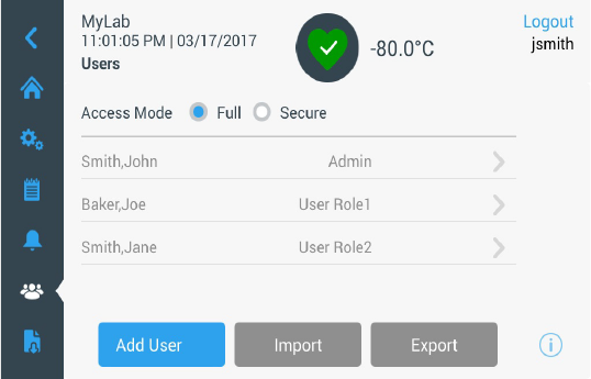
9.6 Users The User tab is used to display the Users screen. Access Mode is used to
change the access mode for the system (full or secured), add a user to the
system, and to import and/or export a user database. The following screen is
displayed when the User icon is selected:
Figure 53. Users Screen
The Import button allows a user database to be imported.
Note: The database to be imported must be taken from another unit running
the same software otherwise the system will not recognize the database.
The user database can be exported using the Export button. A USB drive
must be inserted for the data to be transferred.

Operation
46 Installation and Operation Thermo Fisher Scientific Ultra Low Temperature
9.6.1 Adding New Users Select the Add User button to navigate to the Add a User screen:
Figure 54. Add a User Screen
Fill in the information in the fields and press Add User. An asterisk denotes
a required field.
• First Name: Enter the user’s first name.
• Last Name: Enter the user’s last name.
• Email: Enter the user’s email address.
• User Name: Enter the user name as required. A default will appear based
upon the email address entered.
• Password: Enter and confirm a user password. The password entered
should be 3-16 characters long, have at least 1 uppercase, 1 number and
1 special character.
• Phone: Enter a user telephone number. Additional phone numbers can
be added by pressing the ‘+’ symbol.

Operation
Thermo Fisher Scientific Ultra Low Temperature Installation and Operation 47
• User Role: Select the access level for the user.
• Admin: This user has access to change settings and manage profiles.
• User Level 1: This user has access to change basic functionality such
as temperature and alarm setpoints.
• User Level 2: This user can view the temperature and alarm
information but cannot change the settings (Primarily used when
unit is equipped with HID Access ID, as anyone needing access to
the freezer must have a user role).
• Access ID: Refer to Section 9.6.3 for more information on access cards.
9.6.2 Editing and Deleting
Users
To edit an existing user, press the user entry in the Users screen and User
Details screens will be displayed. Make the required edits by selecting the
appropriate field and changing the information. After making the changes,
press the “Edit User” button and confirm.
To delete a user, select the Delete User button and confirm.
Note: This action cannot be undone.

Operation
48 Installation and Operation Thermo Fisher Scientific Ultra Low Temperature
Figure 55. User Details Screen
9.6.3 Managing Access Cards When the Access Card system is installed, the User Details screen allows
assigning cards to each user. Users may then swipe their access card to gain
access to the freezer or login.
To associate an access card to a selected user, press the Access ID field of the
User Details screen (refer to Figure 55) and hold the card at the bottom
center of the LCD screen. The Access ID field will automatically be
populated and you will hear a beep. Only one card may be added per user.
The Access ID must be unique for each user.
9.7 Reports The Report tab is used to export a log or report. The Export Logs and
Reports screen will be displayed when the Report icon is pressed. If Reports
is selected as the Export type, the date range is limited to two options - one
week (default) and one day. Refer to Section 9.4 for more information.
Figure 56. Export Logs and Reports Screen

Operation
Thermo Fisher Scientific Ultra Low Temperature Installation and Operation 49
9.8 Chart The chart displays temperature data.
There can be a maximum of two Y-axis. The left Y-axis is Primary and the
right Y-axis is Secondary. Items displayed on the Primary axis are listed on
the left and the ones displayed on the Secondary axis are listed on the right.
Time is denoted on the X-axis.
Figure 57. Chart with items on Primary axis
Figure 58. Chart with items on Primary and Secondary axes
The four buttons on the bottom of the screen are used to:
• Change the setpoint
• Export the chart
• Edit the chart, refer to Section 9.8.1 for more information
• Expand the chart to full screen or return to the default view.

Operation
50 Installation and Operation Thermo Fisher Scientific Ultra Low Temperature
9.8.1 Editing the Chart When the Pencil icon is selected, the Chart Edit screen is displayed:
Figure 59. Chart Edit Screen
• The X-Axis button allows the user to select a time span of 2, 4, 6 or
8 hours.
• The Items to Chart button allows the user to select the items to be
displayed on the chart. A maximum of four items may be selected.
• Show Event Overlay: Enable quick reference event icons to be displayed
on the top of the chart.

Operation
Thermo Fisher Scientific Ultra Low Temperature Installation and Operation 51
Figure 60. Items to Chart Screen
• The Primary Y-Axis button allows the user to set the temperature range.
If Auto is selected, the temperatures are automatically set. If Manual is
selected, the user has to specify the high and low temperatures.
Figure 61. Primary Y-Axis Set screen

Operation
52 Installation and Operation Thermo Fisher Scientific Ultra Low Temperature
• The Secondary Y-Axis button allows the user to set the temperature
range. If Auto is selected, the temperatures are automatically set. If
Manual is selected, the user has to specify the high and low
temperatures. Item associated with the Secondary Y-Axis will be
displayed as a dotted line. The Axis On toggle button is used to enable
the Secondary Y-axis.
Figure 62. Secondary Y-Axis Set Screen
9.8.2 Event Icons Icons related to events will appear on the top of the chart.
Icon Description
Door Open
Power Failure
Temperature Alarm
Service
Multiple Events
Connected to InstrumentConnect™
Connected to Wi-Fi

Health Status and Alarm Management
Thermo Fisher Scientific Ultra Low Temperature Installation and Operation 53
10 Health Status
and Alarm
Management
10.1 Health Status
Overview
Selecting the Health Status (green heart) icon in the home screen displays
the following screen:
Figure 63. Health Status Screen
•
Door Openings:
Total displays the number of times the door has been
opened since the last reset. Last Open displays the duration the door was
last opened. Press the Reset icon to change the Door Openings values to
0.
• Temperature Excursions: Actual displays the current cabinet
temperature. Warm and Cold displays are the highest and lowest
temperatures recorded since the last reset. Press the Reset icon to set the
Warm and Cold values to the current cabinet temperature.
• Conditions: Voltage displays the input voltage. Ambient displays the
unit ambient temperature. By pressing the Conditions Detail button the
following screen will be displayed:
Figure 64. Conditions Detail Screen

Health Status and Alarm Management
54 Installation and Operation Thermo Fisher Scientific Ultra Low Temperature
• Power Modes: Displays the state of the on-board voltage conditioning
system.
• Main Battery: Displays the voltage of the main battery. There is also a
12 month countdown timer that should be reset every time the battery
is replaced.
• Backup System (BUS): The BUS information will be displayed if a BUS
is present.
Selecting the System Dashboard button in Figure 63 displays the on board
sensor readings.
Figure 65. System Dashboard Screen
When a BUS is present, the BUS RTD and BUS battery values are also
displayed.

Health Status and Alarm Management
Thermo Fisher Scientific Ultra Low Temperature Installation and Operation 55
10.2 Notifications /
Cautions
In the event of a notification, the green heart is replaced by a yellow triangle
icon. The number in the blue circle indicates the total number of
notifications.
A yellow triangle on the home screen indicates less serious caution
conditions, such as extended door openings and alarms that occurred in the
past.
Figure 66. Home Screen with Notification / Caution
Press the yellow triangle to display additional notification details.
Figure 67. Notification / Caution Details
The Acknowledge button becomes highlighted in blue once a notification is
selected by pressing the adjacent checkbox. The notification will be
displayed until it is acknowledged. There is a link to the Event Log beside
the Acknowledge button.
On the right panel, the Health Status details can also be viewed.

Health Status and Alarm Management
56 Installation and Operation Thermo Fisher Scientific Ultra Low Temperature
10.3 Alarms / Warning In the event of an alarm condition, the green heart or yellow triangle is
replaced by a red bell icon.
A red bell alarm on the home screen indicates a
serious alarm condition which must
be corrected
,
such as a warm alarm or a
power failure.
The alarm can be silenced by pressing the Snooze button or
the Red Bell icon which will mute the alarm for a duration set in the Snooze
Timeout setting.
The number in the blue circle indicates the total number of alarms. The
icon to the right of the bell helps identify the alarm type. The ticker message
provides alarm details.
Figure 68. Home Screen with Alarm / Warning
Press the red bell for additional information about the alarms.
Figure 69. Alarm / Warning Detail Screen
If an alarm and a notification occur at the same time, the alarm red bell icon
is displayed and the list includes both alarms and notifications.

Backup System (Optional)
Thermo Fisher Scientific Ultra Low Temperature Installation and Operation 57
The Acknowledge button becomes highlighted in blue once an alarm is
selected by pressing the adjacent checkbox. Active alarms cannot be cleared
until the issue is addressed. There is a link to the Event Log beside the
Acknowledge button.
On the right panel, the Health Status details can also be viewed.
For more information on various alarm conditions, refer to Appendix A:
Alarm Summary.
11 Backup System
(Optional)
When you purchase a built-in CO
2
or LN
2
optional backup system for the
freezer, backup control is integrated into the main user interface.
Note: Always purchase the cylinders which are equipped with siphon tubes for
withdrawing liquid from the bottom of the cylinder. CO
2
cylinders must be kept
at room temperature to function properly. LN
2
bottles are functional at any
reasonable temperature.
11.1 CO
2
and LN
2
Precautions
The following are precautions for using liquid CO
2
and LN
2
backup
systems.
WARNING: If a CO
2
or LN
2
cylinder falls and a valve is knocked off, the
cylinder becomes a deadly and completely unguided missile. Transport the
cylinders in a hand-truck or cart with secure chain ties for the cylinder. After
cylinders are connected to the equipment, securely attach them with chains
to a solid, stationary object such as a building column.
WARNING: CO
2
and LN
2
liquids are non-poisonous but are very cold
and will burn unprotected skin. Always wear protective eye wear and
clothing when changing cylinders or working on the piping systems
attached to an active source of liquid refrigerant.
WARNING: The gases produced by evaporation of CO
2
or LN
2
are
non-poisonous but displace the oxygen in a confined space and can cause
asphyxiation. Do not store the cylinders in subsurface or enclosed areas.
CAUTION: When closing the cylinder valve, make sure that the injection
solenoid is energized to allow all the liquid to bleed off instead of being
trapped in the supply hose. Failure to do this results in activation of the
pressure relief device, which could damage the freezer and requires replacing
if it is activated.

Backup System (Optional)
58 Installation and Operation Thermo Fisher Scientific Ultra Low Temperature
CAUTION: For models ordered with factory installed built-in backup
systems, the flow of liquid CO
2
or LN
2
will be discontinued if the door is
opened during operation of the backup system. For units operated with
free-standing, field installed type backup system, the flow of liquid CO
2
or
LN
2
will be discontinued upon door opening only if the switch provided
with the free-standing package is installed on the freezer.
11.2 Installation Field installed systems are supplied with complete installation and operating
instructions. If your system is factory installed, the freezer is shipped with a
coiled length of hose to connect the freezer to the bottles:
• 1/4" Flexible Hose with fittings for connection to the CO
2
supply.
• 1/2" Flexible Hose with fittings for connection to the LN
2
supply.
To install,
1. Straighten the coiled hose.
2. Connect one end to the labeled connection on the freezer.
• Tighten the nut two flats past finger tight, approximately 120 degrees.
Note: For CO
2
, remove the threaded fitting from the nut on the end of the
copper tubing to access nut for connection to the freezer. Discard the threaded
fitting.
3. Attach the other end to the supply bottle or building supply fitting.
• For CO
2
:
• Remove Nipple from adapter (NPT Connection).
Remove cable tie to release alternative nut and washer.
Ensure the correct nut fitting is supplied over the nipple (US or
European).
• Add 2 wraps of Teflon tape clockwise to the 1/4" NPT fitting (on
the nipple) when viewed from the threads. Tighten the NPT fittings
approximately 2 turns from finger tight (approximately 720°).
Note: The top of the nipple has a hex configuration, allowing for use of a
wrench when the nut is pulled down.
• Add washer to nipple inside of nut (unless CO
2
supply has a built in
washer).

Backup System (Optional)
Thermo Fisher Scientific Ultra Low Temperature Installation and Operation 59
Note: Small raised area of washer fits into groove of nipple. The washer will feel
snug when trying to shift side to side on nipple. The washers are designed for a
limited number of attachments/disconnections from the supply and may wear
over time. If washer appears worn and causes CO
2
leakage, replace washer (Part
Number 45705H03).
• Wrench tighten the supply nut to the supply.
•For LN
2
:
• Attach the fitting to the supply and wrench tighten.
Note: Do not twist, torque, or subject the flexible hose to sharp bends. Doing so
may shorten the life of the hose.
11.3 Start Up To activate the backup system:
1. Follow the instructions in Section 8 to turn on the freezer and set
temperature and alarm set points.
2. Select the backup type and backup set point on the Backup Setting
Screen below, which can be accessed through the Controls option in the
Settings tab (refer to Figure 36).
Figure 70. Backup System Settings Screen
3. Press the Save button to save the changes made.

Chart Recorders (Optional)
60 Installation and Operation Thermo Fisher Scientific Ultra Low Temperature
11.4 Operation When the backup system is in operation, the parameters can be viewed and
configured on the settings screen.
Once the backup system has been activated, it can be tested by pressing the
Test button. The system will inject as long as the button is being pressed.
The backup system can run for a minimum of 24 hours on battery power.
On average, a backup system in operation uses 8 to 10 lbs. per hour of CO
2
(3.6 to 4.5 L/hr) or LN
2
(4.5 to 5.6 L/hr) at an ambient temperature of
25°C.
12 Chart Recorders
(Optional)
Panel-mounted six-inch seven-day recorders are available as options for all
freezer models except for the smallest (300 box capacity) models.
12.1 Set Up and
Operation
To prepare the recorder to function properly, complete the following steps:
1. Open the grille door to access the recorder.
2. Install clean chart paper (refer to Section 12.2).
3. Remove the plastic cap from the pen stylus or ink pen and close the
recorder door.
Recorder operation begins when the system is powered on.The recorder may
not respond until the system reaches temperatures within the recorder’s
range.
Figure 71. Chart Recorder
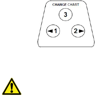
Chart Recorders (Optional)
Thermo Fisher Scientific Ultra Low Temperature Installation and Operation 61
Figure 72. Chart Buttons
CAUTION: Do not use sharp or pointed objects to depress the chart
buttons. This may cause permanent damage to the recorder.
12.2 Changing Chart
Paper
To change the chart paper, complete the following steps:
1. Locate the pressure sensitive buttons at the front, upper left of the
recorder panel.
2. Press and hold the Change Chart button (#3) for one second. The pen
will move off the scale.
3. Unscrew the center nut, remove the old chart paper, and install new
chart paper. Carefully align the day and time with the reference mark (a
small groove on the left side of the recorder panel).
4. Replace the center nut and hand tighten. Press the Change Chart button
again to resume temperature recording.
12.3 Calibration
Adjustment
This recorder has been accurately calibrated at the factory and retains
calibration even during power interruptions. If required, however,
adjustments can be made as follows:
1. Run the unit continuously at the control set point temperature.
Continue steady operation for at least two hours to provide adequate
time for recorder response.
2. Measure cabinet center temperature with a calibrated temperature
monitor.
3. Compare the recorder temperature to the measured cabinet
temperature. If necessary, adjust recorder by pressing the left (#1) and
right (#2) chart buttons.
Note: The stylus does not begin to move until the top center button (#3) is held
for five seconds.

Maintenance and Troubleshooting
62 Installation and Operation Thermo Fisher Scientific Ultra Low Temperature
13 Maintenance and
Troubleshooting
WARNING: Unauthorized repair of your freezer will invalidate your
warranty. Contact Technical Service at 1-800-438-4851 for additional
information.
CAUTION: Maintenance should only be performed by trained personnel.
13.1 Cleaning the
Condenser
Clean the condenser at least every six months; more often if the laboratory
area is dusty.
To clean the condenser, complete the following steps:
1. Pull the grille door open.
2. Vacuum the condenser.
3. Inspect the filter cleanliness and clean as required.
4. Close the grille door.
13.2 Cleaning the
Condenser Filter
Clean the condenser filters every two or three months.
There are two condenser filters: a main filter and a lower filter for extra air
flow into the condenser.
1. Pull the grille door open.
2. Remove the filters.
3. Shake the filters to remove loose dust, rinse the filters in clean water,
shake the excess water from the filters, and replace the filters.
4. Close the grille door.
13.3 Gasket
Maintenance
Periodically check the gaskets around the door for punctures or tears. Leaks
are indicated by a streak of frost which forms at the point of gasket failure.
Make sure that the cabinet is level (refer to Section 7.3 for leveling
information).
Keep the door gaskets clean and frost free by wiping gently with a soft cloth.
Maintenance and Troubleshooting
Thermo Fisher Scientific Ultra Low Temperature Installation and Operation 63
13.4 Defrosting the
Freezer
Defrost the freezer once per year or whenever the ice buildup exceeds 3/8".
To defrost, complete the following steps:
1. Remove all products and place in another ULT cabinet.
2. Turn off the freezer.
3. Open the outer door and all inner doors.
4. Let the freezer stand with doors open for at least 24 hours. This allows
both the interior and foamed refrigerant system to warm to room
temperature.
5. Dispose of the ice and wipe out any water standing in the bottom of the
cabinet.
6. If there is freezer odor, wash the interior with a solution of baking soda
and warm water.
7. Clean the exterior with any common household cleaner.
8. Close the doors, restart the freezer and reload. Refer to Section 5.3 to
follow the instructions.
13.5 Battery
Maintenance
The freezer monitors the voltage status of the battery daily and indicates the
battery’s voltage via visual and auditory alarm. Replace the battery as indicated by
system alarms or as necessary per individual status evaluation. Check the battery
connections regularly. Although not required, annual battery replacement is
recommended to ensure proper battery status in the event of power failure. Be
sure to reset the battery replacement timer via the user interface whenever the
battery is replaced.
For safety, it is recommended to power off the unit and disconnect it from the
power source before replacing the battery. Battery terminals are color coded red
and black. Ensure the corresponding colored wires are connected to the matching
color terminals on the battery. The battery is installed with terminals oriented
toward the condenser compartment or hinge side of the freezer’s outer door (see
below). With proper installation, the red wire should be connected to the rear
battery (positive) terminal and the black wire to the front (common) terminal.
Failure to properly connect the battery can damage electrical components and
potentially hinder normal operation of the freezer. Consult a certified service
technician if there are any questions or concerns about battery maintenance.

Maintenance and Troubleshooting
64 Installation and Operation Thermo Fisher Scientific Ultra Low Temperature
Battery Specification:
Rechargeable sealed lead-acid battery, 12 V, 7.0 Amp Hr.
Replacement batteries can be purchased directly from Thermo Fisher Scientific.
13.6 Maintenance
Schedule
Regular maintenance is important to keep the unit working properly.
Inspect/Clean as directed in the manual.
Item Interval
Defrost Defrost the freezer once per year or whenever the ice build
exceeds 3/8'' (0.95 cm).
Gasket Periodically check the gaskets around the door for punctures
or tears. Periodically clean the ice-build up around the gasket.
Filter Clean the condenser filter(s) every two to three months.
Condenser Clean every six months; more often if the laboratory area is
dusty.
Battery Replace the battery as indicated by system alarms or as
necessary per individual status evaluation. Check the battery
connections regularly. Although not required, annual battery
replacement is recommended to ensure proper battery status in
the event of power failure.

Troubleshooting Guide
Thermo Fisher Scientific Ultra Low Temperature Installation and Operation 65
14 Troubleshooting
Guide
This section is a guide to troubleshooting general operational problems.
Problem Cause Solution
• Unit warming.
• Unit set to –80°C but
can’t make temperature
(Not reaching set
point).
• Unit recovers slowly to
set point.
Warm load / Over load. Allow ample time to recover from loading warm product. Do
not overload cabinet.
Please refer to Section 5.3 in user manual for loading
procedures.
Hot environment. Check, if the location meets ambient requirements (within
15°C to 32°C or 59°F to 90°F) and away from hot objects.
Dirty condenser and
condenser filter.
Clean condenser and filter. Please refer to Section 13.1 and
Section 13.2 in user manual.
Not enough space for air
circulation.
Install the unit in a level area free from vibration with a
minimum of 8 inch (20 cm) of space on the top and sides,
6 inch (15 cm) in back.
Icing/Frost due to high
relative humidity.
Check if the location meets requirements. Maximum relative
humidity 60% for temperatures within 15°C to 32°C (59°F to
90°F).
Excess frost build-up in
chamber.
Defrost the unit. Please refer to Section 13.4 in user manual.
Frost build-up on outer door
gasket.
Occasionally scrape the ice on the gasket.
Gasket damage. Check for punctures or tears on gasket. Replace if necessary.
Please refer to Section 13.3 in user manual.
Prolonged door openings. Avoid opening of door for longer duration. Allow ample time
for recovery after door opening.
Inadequate power supply. Check for proper voltage to the unit.
Either of the compressors
are not working.
Call service.
Refrigerant is insufficient. Call service.
• User interface (Display)
failure.
Breaker switch off. Check circuit breaker and reset to on position. Always use a
dedicated, properly grounded circuit.
User interface not powered
on.
Push power button on user interface and hold for at least
1 second.
• Unit is ON but display
is showing empty.
User interface not powered
on.
Push power button on user interface and hold for at least
1 second. Try touching the screen.
Try restarting the unit manually by flipping the breaker at the
rear of the unit. If this doesn’t work, call service.

Troubleshooting Guide
66 Installation and Operation Thermo Fisher Scientific Ultra Low Temperature
• Display is looking dull.
Screen brightness is too
low.
From the settings screen, pressing the display button will
show the display.
Adjust the brightness level of the display (Refer Section 9.3.2
in user manual).
• Power failure to the
unit.
Power supply stopped /
Breaker switch off.
Confirm that the cord is securely plugged in.
Plug another appliance into the outlet to see if power is
present.
Reset circuit breaker to on position and push power button
on user interface and hold for at least 1 second.
Always use a dedicated, properly grounded circuit.
For the TSX series, the ULT should not be connected to a
GFCI (Ground Fault Circuit Interrupter) protected outlet as it
may be subject to nuisance tripping.
• Unit tripping the circuit
breaker.
Shared power source. Never connect unit to overloaded power source. Always use a
dedicated (separate) circuit.
Unit plugged into wrong
power outlet.
Plug the unit into proper power source to deliver correct
voltage.
Unit not grounded. Your unit must be properly grounded in conformity with
national and local electrical codes. Troubleshooting
procedures involving live voltage is dangerous and if done
improperly can result in injury and/or death. This
troubleshooting should be performed by trained personnel
only.
Use of GFCI for TSX units. For the TSX series, the ULT should not be connected to a
GFCI (Ground Fault Circuit Interrupter) protected outlet as it
may be subject to nuisance tripping.
Use of extended cords. Do not use an extension cord. Make sure the unit supplied
power cord is plugged directly into power outlet.
• Excessive frost
build-up around
perimeter of door.
Icing/Frost due to high
relative humidity.
Check if the location meets requirements. Maximum relative
humidity 60% for temperatures within 15°C to 32°C (59°F to
90°F).
Occasionally scrape the ice on the outer door.
Excessive and prolonged
door openings.
Avoid opening door for a prolonged time.
Gasket damage. Check for punctures or tears on gasket. Replace if necessary.
Please refer to Section 13.3 in user manual.
Problem Cause Solution

Troubleshooting Guide
Thermo Fisher Scientific Ultra Low Temperature Installation and Operation 67
• Unit is over cooling.
Set points may have
changed.
Adjust the set point to run at desired set point under settings.
Refer to Section 9.3.5 in user manual.
Temperature offset may
have changed.
Try adjusting the offset. Temperature offset can be set in the
Controls screen under settings. (Please refer to Section 9.3.5
in user manual).
Unknown. Try re-starting the unit. If this doesn’t help call service.
• Unit compressors run
continuously.
Freezer set point is low. Check whether the setpoint is in operating range. Change the
setpoint if necessary.
Frost build up. Defrost the unit. Please refer to Section 13.4 in user manual.
Dirty condenser. Clean the condenser and condenser filter.
Gasket damage. Check for punctures or tears on gasket. Replace if necessary.
Please refer to Section 13.3 in user manual.
• Cabinet temperature
reached an alarm
condition, but suitable
alarm is not activated.
Alarm setpoints may be
changed.
Check the present setpoints for temperature alarm conditions.
Change the set points if required. Please refer to Section 9.3.1
in user manual.
• Problem with
temperature
validation/calibration.
Cabinet temperature
displayed doesn’t match
with actual temperature.
Customers performing on-site temperature calibration may
observe as much as a 2°C variation when an external probe is
placed next to the freezer control probe. This variation is
normal, due to optimisation of control system to ensure
temperature uniformity throughout the cabinet.
• Unit is experiencing too
much cabinet
temperature fluctuation
(high uniformity / peak
variation).
Operating mode selected. Change power mode to high-performance mode to have
tighter peak variation. Refer to Section 9.3.5 in manual.
• Unit is constantly
alarming.
Exterior door is closed but
not sealed completely.
Clean any ice build-up on gasket and/or cabinet surface.
Check for punctures or tears on gasket. Replace if necessary.
Please refer to Section 13.3 in user manual.
Alarm icons appear on user
interface home screen.
By pressing red bell or yellow triangle, the ticker message
provides alarm details and recovery details. Please Refer to
Section 10.3 in user manual.
Door open alarm, exterior
door not closing
completely.
Open door completely and immediately close and latch it.
Door open alarm, exterior
door is closed but not sealed
completely.
Defrost exterior door gasket and make sure the door is
completely sealed.
Alarm set points may have
changed.
Change the set points as required. Please refer to Section 9.3.1
in user manual.
Problem Cause Solution

Troubleshooting Guide
68 Installation and Operation Thermo Fisher Scientific Ultra Low Temperature
• Unit cycle on-
percentage is increasing.
(Compressors are
running more often than
before.)
Ambient conditions. Unit performance is directly impacted by these causes
mentioned. Try maintaining ambient conditions, reducing
load, reducing door openings.
Once temperature is stable, cycle dynamics should return to
normal range. If not call service.
Warm load (or) over load.
Frequent and prolonged
door openings.
• Difficult to close / open
the outer door.
• Outer door alignment
issues.
Unit is not level. Make sure the unit is level.
Please refer to Section 7.3 in the user manual for levelling
procedure.
Frost accumulated on outer
door gasket.
Scrape the ice occasionally on outer door gasket.
Door latch problem. Ensure door latch is securing. Lubricate the door latch
mechanism.
Pressure Equilization Port
(PEP) malfunctioning
The PEP is located behind the user interface but the backside
of the port can be seen on the inside surface of the exterior
door.
If the opening or area directly in front of the opening is filled
or covered with ice and/or frost, remove the blockage. Try
closing and re-opening the door.
If issues persist, call service.
• Difficult to close / open
the inner door.
Frost accumulated around
inner door.
Defrost the inner door.
Inner door latches
damaged.
Call service.
• Vibration noise.
• Rattling noise/ Loud
noise.
Unit is not level. Check if the unit is installed in a level area free from vibration.
(Refer to Section 7.3 in user manual)
Loose side panels. Check side panel screws, tighten them if necessary.
Rubber tubing separators
and/or compressor
dampeners may have
loosened.
Call service.
Problem Cause Solution

Connectivity Troubleshooting
Thermo Fisher Scientific Ultra Low Temperature Installation and Operation 69
15 Connectivity
Troubleshooting
This section is a guide to troubleshooting general connectivity problems.
Problem Cause Solution
• Wireless Network (SSID)
is not appearing in
configuration
Wrong network name Verify the correct network name was provided.
Network (SSID) is not
visible (Not being
broadcasted)
Verify the network (SSID) is visible (being broadcasted) using
a mobile device.
*Thermo Fisher Devices are not able to connect to SSID’s that
are not being broadcasted.
Network is not compatible
with the Thermo Fisher
802.11 AC network card
Verify with Local IT the network is compatible with the
Thermo Fisher 802.11 AC network card.
*Wireless 802.11 AC is compatible with 802.11 B, 802.11 G,
and 802.11 N.
*Freezers only support the 2.4GHz frequency. 5Ghz SSID is
not supported.
UI firmware Contact service.
• Freezer will not connect
to a Wireless Network
Wrong SSID and Password Verifiy you are connecting to the correct network (SSID) and
are entering the correct password. (Suggestion: attempt the
same network connection via an alternate device, like a cell
phone, laptop, or tablet.)
Try restarting the freezer and re-attempt to establish the Wi-Fi
connection.
Network requires user
acceptance or input via a
web browser (like at a hotel)
Verify wireless access is not dependent on accessing a web
page first.
*Freezer is not compatible with Wi-Fi networks that require a
login via webpage, such as many “guest” or “visitor”
networks. Using such a network will cause the WiFi
connection to fail.
Enterprise security(802.1x) Freezers do not support enterprise class authentication.
Work with Local IT to get access to a network (SSID) with
standard authentication.
Weak Signal Strength
(RSSI)
Verify Signal Strength (RSSI) is at least -65 dBm or better at
the wireless interface of the device.
MAC Address Filtering Verify with local IT if MAC address filtering is in place.
If MAC address filtering is in place, work with local IT to get
the device added to an approved list.
Navigate to Settings, Connectivity and WIFI to see the MAC
address.

Connectivity Troubleshooting
70 Installation and Operation Thermo Fisher Scientific Ultra Low Temperature
Note: After resetting (like a unit factory reset) and reconnecting to
InstrumentConnect, the freezer will appear as a new connection within the user's
connected devices on InstrumentConnect. This is because a new security
certificate will be established. The freezer will be unable to re-connect to the
original device under the "old" security certificate.
• Connectivity Options in
freezer UI are greyed out
and non-responsive
• Device not connecting to
the Cloud Portal
Firewall ports closed Verify with local IT that that ports 443, 123, and 80 are open
to the Internet in the facility's firewall.
Use the telnet app from a computer on the same network
*Telnet is NOT enabled by default in Windows
*telnet apps.thermofisher.com 443
*telnet apps.thermofisher.com 80
*telnet apps.thermofisher.com 123
Proxy server Verify with local IT that internet access is not gated behind a
proxy server.
*Thermo Fisher smart devices do not support proxy server
configuration
Connect device to cloud
using 3G/4G hotspot
Confirm if the Hotspot works at the location and allows
internet connection using a laptop or tablet.
If the device connects to the cloud, the issue is with the IT
security. Work With Local IT to resolve the issue.
If device does not connect through a hotspot, call service.
UI firmware Call service.
Problem Cause Solution
Warranty
Thermo Fisher Scientific Ultra Low Temperature Installation and Operation 71
16 Warranty Be sure to register your warranty online:
www.thermofisher.com/labwarranty
THERMO FISHER SCIENTIFIC USA FREEZER WARRANTY FOR
TSX SERIES
The Warranty Period starts two weeks from the date your equipment is
shipped from our facility. This allows for shipping time so the warranty will
go into effect at approximately the same time your equipment is delivered.
The warranty protection extends to any subsequent owner during the
warranty period.
During the first five years of the warranty period, component parts proven
to be non-conforming in materials or workmanship will be repaired or
replaced at Thermo Fisher Scientific's expense, labor included. The ULT
Freezers include an additional seven year warranty on the compressors, parts
only, F.O.B. factory. Installation and calibration is not covered by this
warranty agreement. The Technical Services Department must be contacted
for warranty determination and direction prior to any work being
performed. Expendable items, i.e., glass, filters, pilot lights, light bulbs and
door gaskets are excluded from this warranty.
Replacement or repair of component parts or equipment under this
warranty shall not extend the warranty to either the equipment or to the
component part beyond the original five year warranty period. The
Technical Services Department must give prior approval for the return of
any components or equipment.
THIS WARRANTY IS EXCLUSIVE AND IN LIEU OF ALL OTHER
WARRANTIES, WHETHER WRITTEN, ORAL, OR IMPLIED. NO
WARRANTIES OF MERCHANTABILITY OR FITNESS FOR A
PARTICULAR PURPOSE SHALL APPLY. Thermo shall not be liable for
any indirect or consequential damages including, without limitation,
damages relating to lost profits or loss of products.
Your local Thermo Fisher Scientific Sales Office is ready to help with
comprehensive site preparation information before your equipment arrives.
Printed instruction manuals carefully detail equipment installation,
operation, and preventive maintenance.
If equipment service is required, please call your Technical Services
Department at 1-800-438-4851 (USA and Canada). We're ready to answer
your questions on equipment warranty, operation, maintenance, service,
and special applications. Outside the USA, contact your local Thermo
Fisher Scientific office or distributor for warranty information.
Warranty (International)
72 Installation and Operation Thermo Fisher Scientific Ultra Low Temperature
17 Warranty
(International)
THERMO FISHER SCIENTIFIC FREEZER INTERNATIONAL
WARRANTY FOR TSX SERIES
The Warranty Period starts two months from the date your equipment is
shipped from our facility. This allows for shipping time so the warranty will
go into effect at approximately the same time your equipment is delivered.
The warranty protection extends to any subsequent owner during the
warranty period. Dealers who stock our equipment are allowed an
additional four months for delivery and installation, providing the warranty
card is completed and returned to the Technical Services Department.
During the first five years of the warranty period, component parts proven
to be non-conforming in materials or workmanship will be repaired or
replaced at Thermo Fisher Scientific's expense, labor excluded. The ULT
Freezers include an additional seven year warranty on the compressors, parts
only, F.O.B. factory. Installation and calibration is not covered by this
warranty agreement. The Technical Services Department must be contacted
for warranty determination and direction prior to any work being
performed. Expendable items, i.e., glass, filters, pilot lights, light bulbs and
door gaskets are excluded from this warranty.
Replacement or repair of component parts or equipment under this
warranty shall not extend the warranty to either the equipment or to the
component part beyond the original five year warranty period. The
Technical Services Department must give prior approval for the return of
any components or equipment.
THIS WARRANTY IS EXCLUSIVE AND IN LIEU OF ALL OTHER
WARRANTIES, WHETHER WRITTEN, ORAL, OR IMPLIED. NO
WARRANTIES OF MERCHANTABILITY OR FITNESS FOR A
PARTICULAR PURPOSE SHALL APPLY. Thermo shall not be liable for
any indirect or consequential damages including, without limitation,
damages relating to lost profits or loss of products.
Your local Thermo Fisher Scientific Sales Office is ready to help with
comprehensive site preparation information before your equipment arrives.
Printed instruction manuals carefully detail equipment installation,
operation, and preventive maintenance.
If equipment service is required, please contact your local Thermo Fisher
Scientific office or local distributor.
We're ready to answer your questions on equipment warranty, operation,
maintenance, service, and special applications. Outside the USA, contact
your local Thermo Fisher Scientific office or distributor for warranty
information.

Appendix A: Alarm Summary
Thermo Fisher Scientific Ultra Low Temperature Installation and Operation 73
Appendix A: Alarm
Summary
Alarm Summary
Alarm Message Tone
Heart
Status
Remote
Alarm
Event
Ringback
*
Message Details
Warm Alarm Active High Red Yes Yes
Message Header: Warm Alarm
Message Details: The freezer temperature has
exceeded the warm alarm set point of XX.X C.
Prolonged door openings and warm product loading
may cause warm alarms.
Ticker Message: Warm Alarm active. Press bell
icon for more information.
Warm Alarm Inactive None Yellow None None
Message Header: Warm Alarm Recovered
Message Details: The freezer temperature has
recovered from a warm alarm event. Select check
box and press Acknowledge to clear this
notification.
Ticker Message: None
Cold Alarm Active High Red Yes Yes
Message Header: Cold Alarm
Message Details: The freezer temperature has
exceeded the cold alarm set point of XX.X C
Ticker Message: Cold Alarm active. Press bell icon
for more information.
Cold Alarm Inactive None Yellow None None
Message Header: Cold Alarm Recovered
Message Details: The freezer temperature has
recovered from a cold alarm event. Select check box
and press Acknowledge to clear this notification.
Ticker Message: None
Door Open Ajar High Red Yes Yes
Message Header: Door Open Alarm
Message Details: Door open for greater than 3
minutes will cause door open alarm.
Ticker Message: Door Open Alarm active. Press
bell icon for more information.
Door Open Recovered None Yellow None None
Message Header: Door Open Recovered
Message Details: Door open alarm has recovered.
Select check box and press Acknowledge to clear
this notification.
Ticker Message: Door Open Alarm active. Press
bell icon for more information.

Appendix A: Alarm Summary
74 Installation and Operation Thermo Fisher Scientific Ultra Low Temperature
System Battery Low None Yellow None None
Message Header: System Battery Low
Message Details: System battery is XX.XV.
Recommend replacing battery. Contact customer
service for replacement battery.
Ticker Message: None
System Battery PM
Expiry
None Yellow None None
Message Header: System Battery Low
Message Details: System battery is XX.XV.
Recommend replacing battery. Contact customer
service for replacement battery.
Ticker Message: None
BUS Battery Low None Yellow None None
Message Header: BUS Battery Low
Message Details: BUS battery is XX.XV.
Recommend replacing battery. Contact customer
service for replacement battery.
Ticker Message: None
BUS Battery PM
Expiry
None Yellow None None
Message Header: Battery PM Expiry
Message Details: Recommend to replace battery.
Reset battery expiration time on XXX screen to
clear this notification.
Ticker Message: None
Extreme Ambient None Yellow None None
Message Header: Extreme Ambient Notification
Message Details: Ambient temperature has
exceeded the Extreme Ambient set point of XX.XC.
Ensure room temperature is properly controlled.
Ticker Message: None
Control Probe Failure High Red Yes Yes
Message Header: Control Probe Failure Alarm
Message Details: Cannot display cabinet
temperature. The freezer will continue to operate in
full run mode. Contact customer service.
Ticker Message: Control Probe Failure Alarm
active. Press bell icon for more information.
Control Probe Failure
has been
None Yellow None None
Message Header: Control Probe Failure Recovered
Message Details: Control Probe Failure Alarm has
been cleared. Press the yellow triangle to clear this
notification.
Ticker Message: None
Alarm Summary
Alarm Message Tone
Heart
Status
Remote
Alarm
Event
Ringback
*
Message Details

Appendix A: Alarm Summary
Thermo Fisher Scientific Ultra Low Temperature Installation and Operation 75
Heat Exchange Probe
Failure
High Red Yes Yes
Message Header: Heat Exchanger Probe Failure
Notification
Message Details: The freezer will continue to
operate with current freezer set points, but cabinet
temperature variation will increase. Contact
customer service.
Ticker Message: Control Probe Failure Alarm
active. Press bell icon for more information.
Heat Exchange Probe
Failure has been
None Yellow None None
Message Header: Heat Exchanger Probe Failure
Recovered
Message Details: Heat Exchange Probe Failure
Alarm has been cleared. Press the yellow triangle to
clear this notification.
Ticker Message: None
TC1-9 Failure None Yellow None None
Message Header: TCXX Out of Range Notification
Message Details: Information TC's has
malfunctioned. This doesn't affect the performance
of the unit. Contact service for further assistance.
Ticker Message: None
TC1-9 has been None Yellow None None
Message Header: TCXX Out of Range Notification
Recovered
Message Details: Information TCXX has
recovered. Select check box and press Acknowledge
to clear this notification.
Ticker Message: None
Main to UI Lost
Communication
High Red Yes Yes
Message Header: Lost Communication Alarm
Message Details: A communication error has
occurred within the system. Contact customer
service.
Ticker Message: Lost Communication Alarm
Active. Press bell icon for more information.
Main to UI Lost
Communication
Inactive
None Yellow None None
Message Header: Lost Communication Alarm
Recovered
Message Details: A communication error has
recovered. Select check box and press Acknowledge
to clear this notification.
Ticker Message: None
Alarm Summary
Alarm Message Tone
Heart
Status
Remote
Alarm
Event
Ringback
*
Message Details

Appendix A: Alarm Summary
76 Installation and Operation Thermo Fisher Scientific Ultra Low Temperature
BUS Lost
Communication
High Red Yes Yes
Message Header: Backup System Communication
Alarm
Message Details: A communication error has
occurred within the back up system. Contact
customer service.
Ticker Message: BUS Lost Communication Alarm
Active. Press bell icon for more information.
BUS Lost
Communication
Inactive
None Yellow None None
Message Header: BUS Lost Communication
Alarm Recovered
Message Details: A BUS communication error has
recovered. Select check box and press Acknowledge
to clear this notification.
Ticker Message: None
Failure to Reach
Setpoint
None Yellow None None
Message Header: Unable to Reach Setpoint
Notification
Message Details: Door openings or product loading
may cause this notification. Allow unit to stabilize.
If condition persists, contact customer service
Ticker Message: None
Compressor
Temperature
None Yellow None None
Message Header: Compressor Temperature
Notification
Message Details: A refrigeration system
temperature has exceeded the compressor
temperature setpoint of XX.X C. Contact customer
service.
Ticker Message: None
Inefficient Buck /
Boost
None Yellow None None
Message Header: Inefficient buck / boost
notification
Message Details: Freezer input voltage is out of
range. Ensure proper supply voltage is applied. If
unable to clear this notification, contact customer
service.
Ticker Message: None
Power Failure Alarm High Red Yes Yes
Message Header: Power Failure Alarm
Message Details: Unit in power failure mode.
Display operating on battery power. Check unit
plug, unit circuit breaker in the ON position, and
supply voltage.
Ticker Message: Power Failure Alarm Active.
Press bell icon for more information.
Alarm Summary
Alarm Message Tone
Heart
Status
Remote
Alarm
Event
Ringback
*
Message Details

Appendix A: Alarm Summary
Thermo Fisher Scientific Ultra Low Temperature Installation and Operation 77
Power Failure Inactive None Yellow None None
Message Header: Power Failure Recovered
Message Details: Power has been restored. Press
the yellow triangle to clear this notification.
Ticker Message: None
Clean Filter Active None Yellow None None
Message Header: Clean Filter Notification
Message Details: Recommend to clean the filter
and condenser. If unable to clear notification,
contact customer service.
Ticker Message: None
Refrigeration System
Failure
High Red Yes Yes
Message Header: System Refrigeration Failure
Alarm
Message Details: An error has occurred within the
refrigeration system. Contact customer service.
Ticker Message: System Refrigeration Failure
Alarm. Press bell icon for more information
Refrigeration System
Failure Inactive
None Red None None
Message Header: System Refrigeration Failure
Recovered
Message Details: An error in refrigeration system
has been recovered.Select check box and press
Acknowledge to clear this notification.
Ticker Message: None
Wrong Power Alarm High Red Yes
None, constant
audible
Message Header: Wrong Power Alarm
Message Details: The unit has detected the wrong
power connected. Please verify the proper voltage.
Ticker Message: Wrong Power Alarm. Press bell
icon for more information.
Wrong Power Alarm
Inactive
None Yellow None None
Message Header: Wrong Power Recovered
Message Details: Wrong Power has been recovered.
Select check box and press Acknowledge to clear
this notification.
Ticker Message: None
Wrong Model Alarm High Red Yes
None, constant
audible
Message Header: Invalid Control Model Alarm
Message Details: Invalid Control Model Alarm.
Contact service to ensure the correct model is
selected for the system to avoid cargo loss.
Ticker Message: Invalid Control Model Alarm.
Press bell icon for more information.
Alarm Summary
Alarm Message Tone
Heart
Status
Remote
Alarm
Event
Ringback
*
Message Details

Appendix A: Alarm Summary
78 Installation and Operation Thermo Fisher Scientific Ultra Low Temperature
Wrong Model Alarm
Inactive
None Yellow None None
Message Header: Invalid Control Model
Recovered
Message Details: Invalid Control Model has been
recovered.Select check box and press Acknowledge
to clear this notification.
Ticker Message: None
Firmware Build
Incompatible
High Red Yes Yes
Message Header: Firmware Build Incompatible
Alarm
Message Details: Firmware build indicates
incompatibility that can result in modules to be
non-coherent.
Ticker Message: Firmware build incompatible.
Press bell icon for more information.
Firmware Build
Incompatible Inactive
None Yellow None None
Message Header: Firmware Build Incompatibility
Recovered
Message Details: Firmware build Incompatibility
recovered. Select check box and press Acknowledge
to clear this notification.
Ticker Message: None
Water Temperature
alarm
None Yellow None None
Message Header: Water Temperature Alarm
Message Details: Water inlet Temperature out of
range
Ticker Message: None
Low Water flow
Alarm
High Red Yes Yes
Message Header: Water flow outside allowable
water flow conditions.
Message Details: Water flow rate must be within
1.9 - 6.06 LPM (0.5 - 1.6 GPM) to provide the
required system cooling environment
Ticker Message: Low water flow detected. Check
water supply
Low Water flow
Alarm Inactive
None Yellow None None
Message Header: Low Water flow Recovered
Message Details: Low water flow recovered on the
unit
Ticker Message: None
System Battery
Disconnected Alarm
High Red Yes Yes
Message Header: System Battery Disconnected
Message Details: System Battery Disconnected
Ticker Message: System Battery has been
Disconnected. Press Bell icon for more information
Alarm Summary
Alarm Message Tone
Heart
Status
Remote
Alarm
Event
Ringback
*
Message Details

Appendix A: Alarm Summary
Thermo Fisher Scientific Ultra Low Temperature Installation and Operation 79
*Ringback refers to the audible alarm activating again after the user presses the Snooze button. The time can be set
in the ‘Snooze Timeout’ option in the Alarm Settings screen.
System Battery
Disconnected Has
been
None Yellow None None
Message Header: System Battery Connected
Message Details: System Battery Connected
Ticker Message: None
Bus Battery
Disconnected Alarm
High Red Yes Yes
Message Header: Bus Battery Disconnected
Message Details: Bus Battery Disconnected
Ticker Message: Bus Battery has been
Disconnected. Press Bell icon for more information
Bus Battery
Disconnected Has
been
None Yellow None None
Message Header: Bus Battery Connected
Message Details: Bus Battery Connected
Ticker Message: None
Bus Probe Fail Alarm High Red Yes Yes
Message Header: Bus Probe Failure
Message Details: Bus Probe Fail has been detected
Ticker Message: Bus Probe Fail Alarm active.
Press Bell icon for more information
Bus Probe Fail Alarm
has been
None Yellow None None
Message Header: Bus Probe Failure
Message Details: Bus Probe fail has been recovered
Ticker Message: None
Alarm Summary
Alarm Message Tone
Heart
Status
Remote
Alarm
Event
Ringback
*
Message Details

Appendix B: Event Log Detail
80 Installation and Operation Thermo Fisher Scientific Ultra Low Temperature
Appendix B: Event
Log Detail
Event Log Entry Detail
Item Message
System Parameter Change
Header: Control Settings Change
Role: Logged in personnel or anonymous in full access mode
Mode: Full access or secured
Message Detail: The following parameters has been changes to:
Parameter 1 from: XX.XX to XX.XX
User Interface Parameter Change
Header: User Interface Settings Change
Role: Logged in personnel or anonymous in full access mode
Mode: Full access or secured
Message Detail: The following parameters has been changes to:
Parameter 1 from: XX.XX to XX.XX
Door Open
Header: Door Open
Role: Logged in personnel or blank if not HID system
Door Close
Header: Door Close
Role: Logged in personnel or blank if not HID system
User Login Header: User jsmith has logged in
User Logout Header: User jsmith has logged out
Door History Reset
Header: Door History Reset
Role: Logged in personnel or anonymous in full access mode
Mode: Full access or secured
Message Detail: Door Usage history has been reset
Temperature Excursion Reset
Header: Temperature Excursion History Reset
Role: Logged in personnel or anonymous in full access mode
Message Detail: Temperature Excursion history has been reset
Add User Event
Header: Add a User to User database
Role: Logged in personnel or anonymous in full access mode
Mode: Full access or secured
Message Detail: User jsmith has been added to user database
Remove User Event
Header: Remove a User to User database
Role: Logged in personnel or anonymous in full access mode
Mode: Full access or secured
Message Detail: User jsmith has been removed to user database
Edit User Event
Header: Edit a User to User database
Role: Logged in personnel or anonymous in full access mode
Mode: Full access or secured
Message Detail: User jsmith details has been modified.

Appendix B: Event Log Detail
Thermo Fisher Scientific Ultra Low Temperature Installation and Operation 81
Buck / Boost Change Event
Header: Buck / Boost status Change
Message Detail:
Buck / Boost changed from X to Y
Line Input Voltage at time of change is
Compensated Voltage at time of change is
BUS Injection Header: BUS Injection on or off
BUS Pressure switch Header: BUS Pressure Switch active or inactive
Reset to Factory default
Header: Reset to Factory Defaults
Role: Logged in personnel or anonymous in full access mode
Mode: Full access or secured
Message Detail: System has been restored to factory defaults
Powered Up Event
Header: Softswitch Power Up event
Role: Logged in personnel or anonymous in full access mode
Mode: Full access or secured
Message Detail: System has been user turned on
Powered Down Event
Header: Softswitch Power Down event
Role: Logged in personnel or anonymous in full access mode
Mode: Full access or secured
Message Detail: System has been user turned off
HID Access Header: User Jsmith has accessed the unit
Invalid HID Header: Invalid HID tried to access unit
Export Event
Header: (Temperature, temperature and event log or pdf report) has been exported
Role: Logged in personnel or anonymous in full access mode
Mode: Full access or secured
Message Detail:
(Temperature, temperature and event log or pdf report) has been exported
Date Range of export is from X to Y
File format exported is (pdf, csv or PUC)
Configuration import / export
Header: Configuration import or export initiated
Role: Logged in personnel or anonymous in full access mode
Mode: Full access or secured
Message Detail: Following items has been imported or exported to USB
- Contact info
- User database
- System and User Interface settings
- Temperature and event log history
Event Log Entry Detail
Item Message

Appendix C: City Time Zone
82 Installation and Operation Thermo Fisher Scientific Ultra Low Temperature
Appendix C: City
Time Zone
Time specified in the time zone indicates the difference with UTC.
Time Zone City Time Zone City
(Africa | +00:00) ElAaiun (Africa | +02:00) Gaborone
Freetown Harare
Lome
Johannesburg
Abidjan
Khartoum
Accra Kigali
Bamako
Lubumbashi
Banjul
Lusaka
Bissau Maputo
Casablanca
Blantyre
Conakry
Bujumbura
Dakar Cairo
Monrovia
Maseru
Nouakchott
Mbabane
Ouagadougou
Tripoli
Windhoek
(Africa | +01:00) Algiers
Bangui (Africa | +03:00) Juba
Brazzaville Kampala
Ceuta
AddisAbaba
Douala
Asmara
Kinshasa DaresSalaam
Lagos
Djibouti
Libreville
Mogadishu
Luanda Nairobi
Malabo
Ndjamena (America | +00:00) Danmarkshavn
Niamey (America | -01:00) Scoresbysund
Porto-Novo
Sao_Tome
Tunis

Appendix C: City Time Zone
Thermo Fisher Scientific Ultra Low Temperature Installation and Operation 83
(America | -02:00) Noronha (America | -04:00) Grenada
Guadeloupe
(America | -03:00) Araguaina Guyana
Bahia
Halifax
Belem
Kralendijk
Cayenne
LaPaz
Fortaleza LowerPrinces
Godthab
Manaus
Maceio
Marigot
Miquelon Martinique
Montevideo
Moncton
Paramaribo
Montserrat
Recife PortofSpain
Santarem
PortoVelho
SaoPaulo
PuertoRico
Santiago
(America | -03:30) StJohns
SantoDomingo
StBarthelemy
Anguilla StKitts
(America | -04:00) Antigua
StLucia
Aruba
StThomas
Asuncion StVincent
Barbados
Thule
Blanc-Sablon
Tortola
BoaVista
CampoGrande (America | -05:00) Atikokan
Caracas
Bogota
Cuiaba Cancun
Curacao
Cayman
Dominica
Detroit
GlaceBay Eirunepe
GooseBay
Guayaquil
GrandTurk
Havana
Time Zone City Time Zone City

Appendix C: City Time Zone
84 Installation and Operation Thermo Fisher Scientific Ultra Low Temperature
(America | -05:00) Iqaluit (America | -07:00) Boise
Jamaica
CambridgeBay
Lima Chihuahua
Nassau
Creston
NewYork
DawsonCreek
Nipigon
Denver
Panama Edmonton
Pangnirtung
FortNelson
Port-au-Prince
Hermosillo
RioBranco Inuvik
ThunderBay
Mazatlan
Toronto
Ojinaga
Phoenix
(America | -06:00) BahiaBanderas
Yellowknife
Belize
Chicago (America | -08:00) Dawson
CostaRica
LosAngeles
ElSalvador
Tijuana
Guatemala Vancouver
Managua
Whitehorse
Matamoros
Menominee (America | -09:00) Anchorage
Merida
Juneau
MexicoCity
Metlakatla
Monterrey Nome
RainyRiver
Sitka
RankinInlet
Yakutat
Regina
Resolute (America | -10:00) Adak
SwiftCurrent
(Antarctica | +00:00) Troll
Tegucigalpa (Antarctica | +03:00) Syowa
Winnipeg
(Antarctica | +05:00) Mawson
(Asia | +04:00) Baku
(Antarctica | +06:00) Vostok Dubai
(Antarctica | +07:00) Davis
Muscat
(Antarctica | +10:00) DumontDUrville
Tbilisi
(Antarctica | +11:00) Casey Yerevan
(Antarctica | +12:00) McMurdo
(Antarctica | +06:00) Vostok (Asia | +04:30) Kabul
Time Zone City Time Zone City

Appendix C: City Time Zone
Thermo Fisher Scientific Ultra Low Temperature Installation and Operation 85
(Antarctica | -03:00) Palmer (Asia | +05:00) Aqtau
Rothera
Aqtobe
Ashgabat
(Arctic | +01:00) Longyearbyen
Dushanbe
Karachi
(Asia | +02:00) Amman
Oral
Beirut Samarkand
Damascus
Tashkent
Famagusta
Yekaterinburg
Gaza
Hebron (Asia | +05:30) Colombo
Jerusalem
Kolkata
(Asia | +03:00) Aden (Asia | +05:45) Kathmandu
Baghdad (Asia | +06:00) Almaty
Bahrain
Dhaka
Kuwait Omsk
Qatar
Qyzylorda
Riyadh
Thimphu
Urumqi
(Asia | +03:30) Tehran
(Asia | +09:00)
Chita
(Asia | +06:30) Yangon
Dili
Jayapura
(Asia | +07:00) Bangkok Khandyga
Barnaul
Seoul
HoChiMinh
Tokyo
Hovd Yakutsk
Jakarta
Krasnoyarsk (Asia | +10:00) Ust-Nera
Novokuznetsk
Vladivostok
Novosibirsk
PhnomPenh (Asia | +11:00) Magadan
Pontianak
Sakhalin
Tomsk
Srednekolymsk
Vientiane
Time Zone City Time Zone City

Appendix C: City Time Zone
86 Installation and Operation Thermo Fisher Scientific Ultra Low Temperature
(Asia | +08:00) Brunei (Asia | +12:00) Anadyr
Choibalsan
Kamchatka
HongKong
Irkutsk (Atlantic | +00:00) Canary
KualaLumpur
Faroe
Kuching
Madeira
Macau Reykjavik
Makassar
StHelena
Manila
Shanghai (Atlantic | -01:00) Azores
Singapore
CapeVerde
Taipei
Ulaanbaatar (Atlantic | -02:00) SouthGeorgia
(Atlantic | -03:00) Stanley
(Asia | +08:30) Pyongyang
(Atlantic | -04:00) Bermuda
(Australia | +08:00) Perth
(Australia | +08:45) Eucla
(Europe | +01:00) Malta
Monaco
(Australia | +09:30) Adelaide Oslo
BrokenHill
Paris
Darwin
Podgorica
Prague
(Australia | +10:00) Brisbane
Rome
Currie
SanMarino
Hobart Sarajevo
Lindeman
Skopje
Melbourne
Stockholm
Sydney Tirane
Vaduz
(Europe | +00:00) Dublin
Va ti ca n
Guernsey Vienna
IsleofMan
Warsaw
Jersey
Zagreb
Lisbon Zurich
London
(Europe | +01:00) Amsterdam (Europe | +02:00) Athens
Andorra Bucharest
Belgrade
Chisinau
Berlin
Helsinki
Bratislava Kaliningrad
Brussels
Kiev
Budapest
Mariehamn
Busingen Riga
Copenhagen
Sofia
Gibraltar
Tallinn
Ljubljana
Uzhgorod
Luxembourg Vilnius
Madrid
Zaporozhye
Time Zone City Time Zone City

Appendix C: City Time Zone
Thermo Fisher Scientific Ultra Low Temperature Installation and Operation 87
(Europe | +03:00) Istanbul
Kirov (Pacific | +11:00) Bougainville
Minsk
Efate
Moscow Guadalcanal
Simferopol
Kosrae
Volgograd
Norfolk
Noumea
(Europe | +04:00) Astrakhan
Pohnpei
Samara
Ulyanovsk (Pacific | +12:00) Auckland
Fiji
(Indian | +03:00) Antananarivo
Funafuti
Comoro
Kwajalein
Mayotte
Majuro
Nauru
(Indian | +04:00) Mahe Tarawa
Mauritius Wake
Reunion
Wallis
(Indian | +05:00) Kerguelen (Pacific | +12:45) Chatham
Maldives
(Pacific | +13:00) Apia
(Indian | +06:00) Chagos Enderbury
(Indian | +06:30) Cocos Fakaofo
(Indian | +07:00) Christmas
Tongatapu
(Pacific | +09:00) Palau
(Pacific | +14:00) Kiritimati
(Pacific | +10:00) Chuuk
(Pacific | -06:00) Easter
Guam
Galapagos
PortMoresby
Saipan (Pacific | -08:00) Pitcairn
(Pacific | -09:00) Gambier
(Pacific | -10:00) Honolulu (Pacific | -09:30) Marquesas
Johnston
Rarotonga
Tahiti
(Pacific | -11:00) Midway
Niue
PagoPago
Time Zone City Time Zone City

WEEE Compliance
WEEE Compliance. This product is required to comply with the European Union’s Waste
Electrical & Electronic Equipment (WEEE) Directive 2012/19/EU. It is marked with the
following symbol. Thermo Fisher Scientific has contracted with one or more
recycling/disposal companies in each EU Member State, and this product should be
disposed of or recycled through them. Further information on our compliance with these
Directives, the recyclers in your country, and information on Thermo Scientific products
which may assist the detection of substances subject to the RoHS Directive are available at
www.thermofisher.com/WEEERoHS.
WEEE Konformittät. Dieses Produkt muss die EU Waste Electrical & Electronic
Equipment (WEEE) Richtlinie 2012/19/EU erfüllen. Das Produkt ist durch folgendes
Symbol gekennzeichnet. Thermo Fisher Scientific hat Vereinbarungen getroffen mit
Verwertungs-/Entsorgungsanlagen in allen EU-Mitgliederstaaten und dieses Produkt muss
durch diese Firmen widerverwetet oder entsorgt werden. Mehr Informationen über die
Einhaltung dieser Anweisungen durch Thermo Scientific, dieVerwerter und Hinweise die
Ihnen nützlich sein können, die Thermo Fisher Scientific Produkte zu identizfizieren, die
unter diese RoHS. Anweisungfallen, finden Sie unter www.thermofisher.com/WEEERoHS.
Conformità WEEE. Questo prodotto deve rispondere alla direttiva dell’ Unione Europea
2012/19/EU in merito ai Rifiuti degli Apparecchi Elettrici ed Elettronici (WEEE).
È marcato col seguente simbolo.Thermo Fischer Scientific ha stipulato contratti con una o
diverse società di riciclaggio/smaltimento in ognuno degli Stati Membri Europei. Questo
prodotto verrà smaltito o riciclato tramite queste medesime. Ulteriori informazioni sulla
conformità di Thermo Fisher Scientific con queste Direttive, l’elenco delle ditte di
riciclaggio nel Vostro paese e informazioni sui prodotti Thermo Scientific che possono
essere utili alla rilevazione di sostanze soggette alla Direttiva RoHS sono disponibili sul sito
www.thermofisher.com/WEEERoHS.
Conformité WEEE. Ce produit doit être conforme à la directive euro-péenne
(2012/19/EU) des Déchets d’Equipements Electriques et Electroniques (DEEE). Il est
marqué par le symbole suivant. Thermo Fisher Scientific s’est associé avec une ou plusieurs
compagnies de recyclage dans chaque état membre de l’union européenne et ce produit
devraitêtre collecté ou recyclé par celles-ci. Davantage d’informations sur laconformité de
Thermo Fisher Scientific à ces directives, les recycleurs dans votre pays et les informations
sur les produits Thermo Fisher Scientific qui peuvent aider le détection des substances
sujettes à la directive RoHS sont disponibles sur www.thermofisher.com/WEEERoHS.
Great Britain
Deutschland
Italia
France

Important
For your future reference and when contacting the factory, please have the following information readily available:
The above information can be found on the dataplate attached to the equipment. If available, please provide the date purchased,
the source of purchase (manufacturer or specific agent/rep organization), and purchase order number.
IF YOU NEED ASSISTANCE:
Thermo Scientific products are backed by a global technical support team ready to support your applications. We also offer cold
storage accessories, including remote alarms, temperature recorders and validation services. Visit www.thermofisher.com or call:
For country contact information not listed, refer to the Contact Us section of www.thermofisher.com
Model Number:
Serial Number:
Date Purchased:
USA/Canada +1 866 984 3766 China
+800 810 5118 (or)
+400 650 5118
France +33 (0)2 2803 2180 India +91 22 6716 2200
Germany
+49 0800 1536 376 Japan 0120-477-392
UK/Ireland
+44 (0) 870 609 9203
opt 3