
April 2020
Interim Revision October 2020
Page1of28
OUTDOOR IGNITABLE LIQUID STORAGE TANKS
Table of Contents
Page
1.0 SCOPE .................................................................................................................................................... 3
1.1 Hazards ............................................................................................................................................. 3
1.2 Changes ............................................................................................................................................ 3
2.0 LOSS PREVENTION RECOMMENDATIONS ........................................................................................ 3
2.1 General ............................................................................................................................................. 3
2.2 Construction and Location ................................................................................................................. 4
2.3 Earthquake ........................................................................................................................................ 5
2.4 Flood .................................................................................................................................................. 5
2.5 Aboveground Tanks ........................................................................................................................... 5
2.6 Outdoor Buried Tanks ........................................................................................................................ 7
2.7 Double-Walled Tanks (Secondary Containment) ............................................................................... 7
2.8 Occupancy ......................................................................................................................................... 8
2.8.1 General .................................................................................................................................... 8
2.9 Protection ........................................................................................................................................... 9
2.10 Venting ............................................................................................................................................. 9
2.10.1 General ................................................................................................................................. 9
2.10.2 Emergency Venting .............................................................................................................. 11
2.10.3 Manifolded Vents ................................................................................................................. 12
2.11 Asphalt Tanks ................................................................................................................................. 14
2.12 Operation and Maintenance .......................................................................................................... 15
2.13 Repair, Reconditioning, and Abandonment ................................................................................... 16
2.14 Human Factor ................................................................................................................................ 16
3.0 SUPPORT FOR RECOMMENDATIONS ............................................................................................... 17
3.1 Tank Construction ........................................................................................................................... 17
3.1.1 Atmospheric Tanks .............................................................................................................. 17
3.1.2 Manifolded Vents ................................................................................................................... 19
3.1.3 Asphalt Tanks ........................................................................................................................ 20
3.1.4 Protection .............................................................................................................................. 21
4.0 REFERENCES ...................................................................................................................................... 21
4.1 FM Global ........................................................................................................................................ 21
4.2 Others .............................................................................................................................................. 22
APPENDIX A GLOSSARY OF TERMS ....................................................................................................... 23
APPENDIX B DOCUMENT REVISION HISTORY ....................................................................................... 25
APPENDIX C JOB AIDS .............................................................................................................................. 27
C.1 Calculating Emergency Venting Requirements (API 2000) ............................................................ 27
List of Figures
Fig. 1. Manifolded tanks .............................................................................................................................. 13
Fig. 2. Required pipe sizing if detonation arrester is smaller than nearby piping ...................................... 14
Fig. 3. Improper piping around detonation arrester ..................................................................................... 14
Fig. 4. Open top double deck ...................................................................................................................... 17
Fig. 5. Open top pontoon ............................................................................................................................ 18
Fig. 6. Pan-type covered tanks .................................................................................................................... 18
Fig. 7. Detonation arrester ........................................................................................................................... 19
FM Global
Property Loss Prevention Data Sheets 7-88
©2020 Factory Mutual Insurance Company. All rights reserved. No part of this document may be reproduced,
stored in a retrieval system, or transmitted, in whole or in part, in any form or by any means, electronic, mechanical,
photocopying, recording, or otherwise, without written permission of Factory Mutual Insurance Company.

Fig. 8. End-of-line flame arrester ................................................................................................................. 20
Fig. 9. End-of-line flame arrester with pipe-away flange ............................................................................. 20
Fig. 10. Backflash interrupter ....................................................................................................................... 21
Fig. 11. Typical conservation vent ................................................................................................................ 24
List of Tables
Table 1. Spacing for Ignitable Liquid Tank Containment Dikes ..................................................................... 6
Table 2. Separation Distance for Remote Impounding Basins ....................................................................... 7
Table 3. Size of Opening for Normal Venting ............................................................................................... 10
Table 4. Required Thermal (Normal) Venting Capacity ................................................................................ 10
Table 5. Typical Vent Line Size for Buried Tanks ......................................................................................... 11
Table 6. Capacities for Emergency Relief of Excessive Internal Pressure for Aboveground Tanks
Operating at 1 psig (7 kPa) or less ................................................................................................ 12
Table 7. Values for L (M)
1/2
for Other Common Liquids ............................................................................... 28
7-88 Outdoor Ignitable Liquid Storage Tanks
Page 2 FM Global Property Loss Prevention Data Sheets
©2020 Factory Mutual Insurance Company. All rights reserved.

1.0 SCOPE
The recommendations in this data sheet apply to ignitable liquids when stored in atmospheric pressure
(operating at less than 1 psig [0.07 barg]) or low pressure (operating over 1 psig [0.07 barg] and less than
15 psig [1 barg]) tanks that are located outdoors (external to buildings) and are greater than 90 ft
3
(2.5 m
3
)
in volume. Additional guidance is also provided for heated tanks containing asphalt.
This data sheet does not cover the following:
• Indoor tanks and vessels; see Data Sheet 7-32, Ignitable Liquid Operations.
• Indoor or outdoor storage of portable containers, including Intermediate Bulk Containers (IBCs). Refer to
Data Sheet 7-29, Ignitable Liquid Storage in Portable Containers.
• Use of IBCs in process; see Data Sheet 7-32, Ignitable Liquid Operations
• Loading stations, pumping stations, process tanks, and day tanks used in production. See Data Sheets
7-32, Ignitable Liquid Operations, and 7-14, Fire Protection for Chemical Plants, for guidance.
• Ignitable liquid or flammable gas stored in pressure vessels above 15 psig (1 barg). See Data Sheet 7-55,
Liquefied Petroleum Gases, for such storages.
• Preventing flame propagation in fuel gas piping systems (see Data Sheet 6-10, Process Furnaces)in
systems handling acetylene (see Data Sheet 7-51, Acetylene), or in fume collection systems for process
equipment (see Data Sheet 7-78, Industrial Exhaust Systems).
1.1 Hazards
The large volumes of ignitable liquids in storage tanks present a significant fire hazard if the liquid is released
from the tank. This may expose other buildings, property, or equipment to severe damage. Other hazards
include overpressurization, implosion, and contamination.
The focus of this data sheet is primarily to protect important buildings and other structures from exposures
to fires involving external storage tanks using space separation, containment, and access to manual
firefighting. Reliance is therefore placed more on containment, separation, and manual firefighting that
automatic fire protection for these tanks.
1.2 Changes
October 2020. Interim revision. The following changes were made:
A. Updated guidance on inhibitors requiring oxygen to maintain activity (to reflect the guidance in Data
Sheet 7-59, Inerting and Purging of Tank, Process Vessels, and Equipment).
B. Updated outdoor storage, high flash point liquid guidance to align with Data Sheet 7-32, Ignitable Liquid
Operations.
2.0 LOSS PREVENTION RECOMMENDATIONS
2.1 General
2.1.1 Locate and protect all liquids, mixtures, emulsions or semi-solids stored in fixed external storage tanks,
that have measurable flashpoints and fire points less than 414°F (212°C), in accordance with this data sheet.
2.1.1.1 Treat liquids that meet one of the following as very high flash point liquids:
A. Unheated liquids with a flash point at or above 414°F (212°C).
B. Heated liquids with a flash point at or above 414°F (212°C) that have an operating temperature that
meets the following equation:
Closed cup flash point – operating temperature > 324°F (180°C).
C. Vegetable oils and fish oils with a closed cup flash point of 450°F (232°C) and greater, that are heated
to less than or equal to 150°F (65°C).
2.1.1.2 Locate and protect very high flash point liquids in outdoor external storage tanks in accordance with
this data sheet.
Outdoor Ignitable Liquid Storage Tanks 7-88
FM Global Property Loss Prevention Data Sheets Page 3
©2020 Factory Mutual Insurance Company. All rights reserved.

2.1.1.3 Liquids, mixtures and emulsions that do not exhibit a fire point are not considered ignitable liquids.
Protection in accordance with this data sheet is not required.
2.1.1.4 For atypical liquids such as silicone fluids, emulsions, propylene and ethylene glycol mixtures and
butterfat see the guidance in Data Sheet 7-32, Ignitable Liquid Operations, to determine whether to treat the
liquid as ignitable or not.
2.1.1.5 For Polymethylene polyphenyl isocyanate (polymeric MDI or PMDI) that is stored in fixed outdoor
tanks, do not provide containment dikes or separation beyond what is (a) necessary for controlling
contamination of adjacent areas or (b) required by local regulations.
PDMI is an ignitable liquid, but the actual fire hazard it creates is limited. A pool of PMDI will only produce
limited flame heights regardless of pool size. A local ignition will spread across the entire pool surface, creating
a large area ignition source. Sprinkler protection is not critical, but containment is important to limit the pool
area.
2.2 Construction and Location
2.2.1 Construct ignitable liquid storage tanks in accordance with a recognized standard, such as one of the
following:
• American Petroleum Institute (API) 650, Welded Steel Tanks for Oil Storage (less than 2.5 psig)
• API Standard 620, Design and Construction of Large, Welded, Low-Pressure Storage Tanks (2.5 – 15
psig)
• API Specification 12B, Bolted Tanks for Storage of Production Liquids
• API Specification 12D, Field Welded Tanks for Storage of Production Liquids
• UL (Underwriters Laboratories) 142, Standard for Steel Aboveground Tanks for Flammable and
Combustible Liquids
• UL 2080, Fire Resistant Tanks for Flammable and Combustible Liquids
• UL 2085, Protected Aboveground Tanks for Flammable and Combustible Liquids
• UL 58, Standard for Steel Underground Tanks for Flammable and Combustible Liquids
• Code for Unfired Pressure Vessels, Section VIII, Division 1 of the ASME Boiler and Pressure Vessel Code
• EN 14015:2004 Specification for the design and manufacture of site built, vertical, cylindrical, flat-bottomed,
above ground, welded, steel tanks for the storage of liquids at ambient temperature and above
• EN BS 14015, Specification for Design and Manufacture of Site Built, Vertical, Cylindrical, Flat-Bottomed,
Aboveground, Welded, Steel Tanks for the Storage OF Liquids at Ambient Temperatures and Above
• EN 12285, Part 1, Workshop Fabricated Steel Tanks: Horizontal Cylindrical Single and Double Skin Tanks
for Underground Storage of Flammable and Non-Flammable Water Polluting Liquids
• EN 12285, Part 2, Workshop Fabricated Steel Tanks: Horizontal Cylindrical Single and Double Skin Tanks
for Aboveground Storage of Flammable and Non-Flammable Water Polluting Liquids
2.2.2 Design tanks of non-combustible construction. If combustible construction cannot be avoided due to
situation or circumstances such as corrosive liquids construct the tanks in accordance with a recognized
standard such as one of the following:
• UL 1316, Standard for Glass Fiber Reinforced Plastic Underground Storage Tanks for Petroleum Products,
Alcohols, and Alcohol-Gasoline Mixtures
• API Specification 12P, Fiberglass Reinforced Plastic Tanks
• ASTM D3299-Standard Specification for Filament Wound Glass Fiber Reinforced Thermoset Resin
Chemical Resistant Tanks.
• ASTM D4097-Standard Specification for Contact Molded Glass Fiber Reinforced Thermoset Resin
Chemical Resistant Tanks.
7-88 Outdoor Ignitable Liquid Storage Tanks
Page 4 FM Global Property Loss Prevention Data Sheets
©2020 Factory Mutual Insurance Company. All rights reserved.

• EN BS 13121 GRP Tanks and Vessels for Use Aboveground. Part 1: Raw Materials - Specification and
Acceptance Conditions. Part 2: Composite Materials - Chemical Resistance. Part 3: Design and
Workmanship. Part 4: Delivery, Installation and Maintenance.
2.2.3 Design supports for tanks to be of fire-resistive construction. Supports are to have a fire resistance of
2 hours or the expected fire duration (whichever is longer) or be protected with an FM Approved fireproof
coating or automatic sprinklers.
2.2.4 Where external insulation is required, provide non-combustible insulation or FM Approved Class 1
insulation.
2.3 Earthquake
2.3.1 For ignitable liquid tanks located in areas subject to earthquakes, provide the following:
A. Tank installations designed as per the guidance in Data Sheet 1-2, Earthquakes
B. Restraint and appropriate flexibility in piping connections and associated tanks, pipe headers, and piping
systems per Data Sheet 1-11, Fire Following Earthquakes.
2.4 Flood
2.4.1 Locate tanks above the design flood elevation and where they will not be subject to direct wave action
associated with coastal flooding. Use Data Sheet 1-40, Flood, to define the design flood elevation and areas
subject to direct wave action. Where this is not possible build the tanks in accordance the guidance in this
data sheet and in DS 1-40, Flood.
2.4.2 Extend all tank vents or other openings that are not liquid-tight above the design flood elevation.
2.5 Aboveground Tanks
2.5.1 Locate exterior aboveground tanks so a release does not expose buildings, equipment and other tanks
to an exposure fire. Site tanks to direct possible liquid releases away from important buildings or installations.
Consider the effect of burning ignitable liquids transported by fire-fighting water in the evaluation.
2.5.2 Locate tanks with respect to buildings in accordance with Table 1.
Outdoor Ignitable Liquid Storage Tanks 7-88
FM Global Property Loss Prevention Data Sheets Page 5
©2020 Factory Mutual Insurance Company. All rights reserved.

Table 1. Spacing for Ignitable Liquid Tank Containment Dikes
Liquid Arrangement
Liquid Flash Point
1, 2, 3
≤ 140°F (60°C) > 140°F (60°C)
Dike wall to buildings of fire-resistive
construction
1L
(min. of 5 ft [1.5 m])
0.5L
(min. of 5 ft [1.5 m])
Dike wall to buildings of
noncombustible construction or open
process structures
1L
(min. of 25 ft [7.5 m])
0.5L
(min. of 15 ft [4.5 m])
Dike wall to buildings of combustible
construction
2L
(min. of 50 ft [15 m])
1L
(min. of 25 ft [7.5 m])
Tank to tank spacing within the diked
area
0.5D
(min. 3 ft [1 m])
0.5D
(min. 3 ft [1 m])
Distance between the outer edge of
the tank and the inner edge of the
containment
0.5D
(min. 3 ft [1 m])
0.5D
(min. 3 ft [1 m])
Tank truck and railcar unloading
stations with no containment, to tank
or buildings
4
75 ft [23 m] 50 ft [15 m]
1
Where dikes contain tanks equipped with internal heating systems and store liquids subject to boil over, froth over, or slop over, protect
as liquids with flash points ≤140°F (60°C) regardless of their flashpoint.
2
L usually refers to the longest containment (dike) dimension, length, width, or diameter (if circular). However, where a noncircular
containment is present, base the spacing to the exposure on the exposing dimension (i.e., the side that most directly faces the exposed
structure, vessel or other dike), not necessarily the longest dimension.
3
D refers to the diameter of the largest flammable liquid tank. For tank-to-tank spacing, this criteria is to facilitate access for maintenance
and manual firefighting. For tank farms that are more than 2 rows wide or irregular in size, larger spacing may be needed.
4
For space separation between loading/unloading stations with containment and buildings, use the same spacings as for tank dikes.
2.5.3 Where spacing between tanks and nearby buildings is inadequate provide one of the following:
A. Provide building construction in accordance with Data Sheet 1-20, Protection Against Exterior Fire
Exposure, using guidelines for yard storage and consider the tanks as high-hazard occupancy.
B. Provide deluge water spray on the exposed wall at a rate of 0.3 gpm/ft
2
(12 mm/min) of exposed wall
using the criteria in DS 1-20 to determine the extent of the exposed wall. Include water supply duration
for 2 hours and at least 500 gpm (1900 L/min) for hose streams.
2.5.4 Where the spacing between the rail or truck load/unload station and buildings is inadequate, provide
exposure protection on the building(s), the load/unload station or both.
2.5.5 Where the spacing between the rail or truck load/unload station and tank farms is inadequate, provide
protection at a rate of 0.30 gpm/ft
2
(12mm/min) as per DS 7-32, Ignitable Liquid Operations, based on the
liquid type present. Include water supply duration for 2 hours and at least 500 gpm (1900 L/min) for hose
streams on the rail or truck load/unload station.
2.5.6 Provide containment for tanks handling liquids with a flash point below 200°F (93°C) by remote
impounding and/or dikes around the tanks.
For liquids with flash points greater than or equal to 200°F (93°C) containment may still be necessary to
prevent contamination of adjacent areas or to satisfy local environmental or government regulations.
2.5.7 Construct dikes to provide containment around the tanks. When calculating the volume of the
containment dike, the volume occupied by tank(s) below the top of the dike may be considered part of the
dike capacity unless the liquid stored is subject to boil over. The volumes of all other tanks below the top of
the dike must be deducted when calculating dike capacity.
A. For tanks of noncombustible construction, size the dike to hold 100% of the contents of the largest
tank within the diked area.
B. For tanks of combustible construction, size dikes to hold 100% of the contents of all the tanks within
the diked area.
C. Construct dike walls of fire-resistive materials such as earth, concrete, or solid masonry, designed to
be liquid-tight and to withstand a full hydrostatic head by release of tank contents.
D. Control vegetation on earthen dikes, so as not to impede fire fighters or add to the fire hazard.
7-88 Outdoor Ignitable Liquid Storage Tanks
Page 6 FM Global Property Loss Prevention Data Sheets
©2020 Factory Mutual Insurance Company. All rights reserved.

E. Provide drainage to remove water from
within diked areas at a minimum uniform slope of 1% away
from tanks toward a sump, a drain box, or other means of disposal located at a safe distance from the tank.
F. Design drains to prevent liquids from entering natural water courses, public sewers, or drains. Trap
drain lines and provide valves on the lines, outside the dike, so they are accessible under fire conditions.
Protect the traps from freezing.
G. Limit dikes to contain an aggregate capacity of 5,000,000 gal (18,900 m
3
), except where individual
tank capacity exceeds 5,000,000 gal (18,900 m
3
) in which case, ensure the dike contains only one tank.
H. Provide individual subdivisions for tank containing unstable liquids using intermediate dikes or channels.
Build intermediate dikes at least 18 in. (0.5m) high.
I. Do not penetrate containment with pipes.
2.5.8 Where remote impounding is used in lieu of full-sized containment as recommended above, the following
guidance applies:
A. Drainage from the diked area to the impounding basin is to be in accordance with Data Sheet 7-83,
Drainage and Containment Systems for Ignitable Liquids.
B. The impounding basin is to have a minimum capacity equal to twice the largest tank that can drain
into it
C. The impounding basin has a means to drain off water accumulations from precipitation
D. Separate the impounding basin from buildings and structures according to the size of the basin and
the exposure potential in accordance with Table 2.
Table 2. Separation Distance for Remote Impounding Basins
Construction Type Separation Distance
• Buildings of ordinary or combustible construction;
• Buildings containing hazardous materials;
• Building with extensive window areas;
• Building with associated combustible yard storage
1.8 x the basin diameter or diagonal
• Buildings of fire-resistive construction;
• Buildings of non-combustible construction;
• Buildings not containing hazardous materials;
• Building without extensive window areas;
• Buildings with no associated combustible yard storage
0.6 x the basin diameter or diagonal
• Ignitable liquid storage tanks 0.3 x the basin diameter or diagonal
2.6 Outdoor Buried Tanks
2.6.1 Locate buried tanks at least 5 ft (1.5 m) from building foundations and 2 ft (0.6 m) from other tanks
and pipelines.
2.6.2 Provide openings for normal venting in accordance with Section 2.10. Venting for fire exposure is
unnecessary.
2.7 Double-Walled Tanks (Secondary Containment)
2.7.1 Secondary containment (i.e., double-walled) tanks do not need additional spill containment by way of
drainage or remote impounding provided they satisfy all of the following criteria:
A. Tanks are listed as meeting the requirements of a specific construction standard (UL 2080, UL 2085,
EN BS 12285, Part 2)
B. The tanks are protected against vehicle impact by suitable barriers except where the tank is specifically
listed and marked as having passed vehicle-impact testing.
C. The tanks are properly supported in accordance with Section 2.2.3.
D. A means to prevent siphon flow from the tank is present.
Outdoor Ignitable Liquid Storage Tanks 7-88
FM Global Property Loss Prevention Data Sheets Page 7
©2020 Factory Mutual Insurance Company. All rights reserved.

E. A means for determining the level of liquid in the tank, that is accessible to the delivery operator is
present.
F. An overfilling system that sounds an alarm when the liquid level in the tank reaches 90% of capacity
and automatically stops delivery of liquid to the tank when the liquid level in the tank reaches 95% of
capacity, without restricting or interfering with the proper functioning of the normal vent or the emergency
vent is present and in operation.
G. All shutdown and interlock systems are tested on at least a monthly basis, with all testing documented.
2.7.2 Locate double-walled tanks with a capacity of 30,000 gal (113 m
3
) or more away from other buildings
and tanks in accordance with the guidance in Table 1.
2.7.3 Double-walled tanks with a capacity less than or equal to 30,000 gal (113 m
3
) that meet all the
recommendations in Section 2.7.1 can be located away from other buildings and tanks as follows:
A. A minimum of 5 ft (1.5 m) from building walls or openings.
B. A minimum of 3 ft (1 m) from adjacent tanks of the same type.
2.8 Occupancy
2.8.1 General
2.8.1.1 Provide the following for connections to outdoor ignitable liquid storage tanks:
A. Steel shutoff valves (manual shutoff valves are acceptable) bolted or welded to the first flange
connection on the tank. Where flanged connections are used, provide noncombustible gasket materials.
Refer to Data Sheet 7-32, Ignitable Liquid Operations, for further information regarding various gasket
materials.
B. A blind flange on the discharge of manual drain valves below the liquid level. .
2.8.1.2 Provide the following for storage tanks containing liquids with flash points at or below 100°F (38°C),
or any ignitable liquid heated above its flash point:
A. FM Approved hazardous location-rated electrical equipment in accordance with Data Sheet 5-1,
Electrical Equipment in Hazardous (Classified) Locations, and national or local codes. Include locations
within 5 ft (1 m) of exterior vents and locations within 10 ft (3 m) of any other tank opening or when located
within a diked area.
B. Tank grounding with a resistance not to exceed1x10
6
Ohms, with FM Approved bonding and grounding
assemblies.
C. Conductive metal fill and discharge lines extending to within 3 in. (76 mm) of the tank bottom that prohibit
discharge above the liquid level in the tank (“splash filling”).
D. A static ground for filling operations.
2.8.1.3 Where quantity or level gauging connections are provided, do the following:
A. Where liquids with a flash point below 100°F (38°C) are present, use a method that will not expose
the vapor space to outside atmosphere.
B. Construct the gauging equipment from materials that are compatible with the materials being measured
and are rated for the temperature, pressure and chemical service conditions under which it will operate.
See Data Sheet 7-32, Ignitable Liquids Operations, for additional guidance.
C. Where a rod and gauging well is provided, extend a pipe down into the tank below the level of the
suction intake to provide a liquid seal at the bottom of the well that prevents vapor above the main body
of liquid from escaping during gauging.
D. Install FM Approved devices for safe gauging (level measurement) of tanks. See Data Sheet 7-32,
Ignitable Liquids Operations, for additional guidance
E. Inspect the equipment on a regular schedule and document all inspections. The frequency of inspections
is to be based on the severity of local conditions.
7-88 Outdoor Ignitable Liquid Storage Tanks
Page 8 FM Global Property Loss Prevention Data Sheets
©2020 Factory Mutual Insurance Company. All rights reserved.

2.8.1.4 To prevent overfilling of tanks, provide high-level alarms that sound at an attended location, to trigger
a manual response for the alarm condition. If manual response is not anticipated nor possible, provide an
automatic high-level alarm connected to an automatic shutoff.
2.8.1.4.1 Monitor fill operations by local operator or remote reading level gauges at an occupied location,
to prevent overfilling.
2.8.1.5 Where heating is required for the free flow of the liquid, do the following:
A. Provide heat only in the vicinity of the suction intake for tanks storing liquids with flash point below
200°F (93°C).
B. Arrange suction pipe or outlet pipe connections to ensure that heating coils will always be submerged.
C. For metal tanks, use steam, hot water or FM Approved electric heaters. For reinforced plastic tanks,
use steam or hot water.
D. Provide a steam pressure-relief valve close to the tank, that is set approximately 5 psi (35 kPa) over
normal working pressure, if steam is supplied through a reducing valve.
E. Provide FM Approved low-liquid-level and high-temperature interlocks to shut off the heating system.
2.9 Protection
2.9.1 Provide hydrants or monitor nozzles within 200 ft (60 m) of tanks so they can be reached by hose
streams or monitor nozzles from outside the dike.
2.9.2 Locate hydrants or monitor nozzles so every tank can be reached by hose or monitor streams from
at least two directions.
2.9.3 FM Approved fixed special protection systems can be used as an alternative to an emergency drainage
system. When a special protection system is provided for this purpose, refer to the guidance in Data Sheet
7-32, Ignitable Liquid Operations, and Data Sheet 4-12, Foam-Water Sprinkler Systems. Containment is
to be provided per this data sheet.
2.9.4 Where foam special protection systems are installed, provide fixed foam outlets and supply piping to
a remote point outside the dike installed in accordance with Data Sheet 4-7N, Low Expansion Foam Systems,
when one or more of the following conditions exists:
A. The tank capacity exceeds 50,000 gal (190 m
3
) or there are multiple tanks in the same dike whose
aggregate capacity exceeds this value.
B. The tanks present a serious exposure to important buildings, process equipment, or utilities due to
inadequate spacing.
C. The tank-to-tank spacing is deficient per this data sheet (Table 1).
2.10 Venting
2.10.1 General
2.10.1.1 Provide breather venting to permit the intake and discharge of air during emptying and filling
operations and to permit expansion and contraction of vapor due to temperature changes.
2.10.1.2 Normal and emergency venting can be provided by one opening with a minimum capacity equivalent
to the emergency vent requirement.
2.10.1.3 For tanks storing liquids with flash points lower than 100°F (38°C), provide pressure and vacuum
relief devices with flame arresters. If connected to a manifolded piping system, use “in-line” type arresters.Any
venting devices are to be normally closed (conservation vents).
2.10.1.4 Prevent condensation in flame arresters on tanks containing liquids that solidify during cold weather
by providing a heating arrangement such as a steam coil at the arrester.
2.10.1.5 Where polymerization of a material may occur at the arrester, provide a dual arrester equipped with
a three-way valve so one arrester is always in service.
Outdoor Ignitable Liquid Storage Tanks 7-88
FM Global Property Loss Prevention Data Sheets Page 9
©2020 Factory Mutual Insurance Company. All rights reserved.

2.10.1.6 For above ground tanks with less than 50,000 gal (189 m
3
) capacity, the vent opening to meet normal
venting requirements can be in accordance with Table 3, but at least as large as the largest of the fill or
withdrawal connection.
Table 3. Size of Opening for Normal Venting
Tank Capacity, gals (m
3
) Minimum diameter, nominal pipe size, in. (mm)
Less than 2,500 (9.5) 1 ¼ (30)
2,500 – 3,000 (9.5 – 11) 1
1
⁄2 (40)
3,001 – 10,000 (11 – 38) 2 (50)
10,001 – 20,000 (38 – 76) 2
1
⁄2 (65)
20,001 – 35,000 (76 – 132) 3 (75)
35,001 – 50, 000 (132 – 189) 4 (100)
2.10.1.6.1 For tanks with a capacity exceeding 50,000 gal (189 m
3
), provide venting as follows:
A. Provide inbreathing (vacuum) capacity of 1 ft
3
/hr free air for each 7.5 gal/hr of the maximum emptying
rate (1 m
3
/hr inbreathing capacity for each 1 m
3
/hr emptying rate) plus the thermal venting capacity given
in Table 4.
B. For tanks storing liquid with a flash point ≤100°F (38°C), provide outbreathing (pressure) capacity of
1 ft3/hr free air for each 3.5 gal/hr of the maximum tank filling rate (1 m
3
/hr free air for each 0.47 m
3
/hr of
the maximum tank filling rate) plus the thermal venting capacity given in Table 4.
C. For tanks storing liquids with a flash point >100°F (38°C), provide outbreathing (pressure) capacity of
1ft
3
/hr free air for each 7.0 gal/hr of the maximum tank filling rate (1 m
3
/hr free air for each 0.94 m
3
/hr
of the maximum tank filling rate) plus the thermal venting capacity given in Table 4.
Table 4. Required Thermal (Normal) Venting Capacity
1
Tank Capacity Vacuum
Pressure
Liquid Flash Point
gal 42-gal
barrels
m
3
All Stocks ≤ 100°F (38°C) >100°F (38°C)
ft
3
/hr m
3
/hr ft
3
/hr m
3
/hr ft
3
/hr m
3
/hr
42,000 1,000 160 1,000 28 1,000 28 600 17
84,000 2,000 320 2,000 57 2,000 57 1,200 34
126,000 3,000 480 3,000 85 3,000 85 1,800 51
168,000 4,000 640 4,000 113 4,000 113 2,400 68
210,000 5,000 800 5,000 142 5,000 142 3,000 85
420,000 10,000 1,600 10,000 280 10,000 280 6,000 170
630,000 15,000 2,400 15,000 420 15,000 420 9,000 255
840,000 20,000 3,200 20,000 570 20,000 570 12,000 340
1,050,000 25,000 4,000 24,000 680 24,000 680 15,000 420
1,260,000 30,000 4,800 28,000 790 28,000 790 17,000 480
1,470,000 35,000 5,600 31,000 880 31,000 880 19,000 540
1,680,000 40,000 6,400 34,000 960 34,000 960 21,000 590
1,890,000 45,000 7,200 37,000 1,050 37,000 1,050 23,000 650
2,100,000 50,000 8,000 40,000 1,130 40,000 1,130 24,000 680
2,520,000 60,000 9,600 44,000 1,250 44,000 1,250 27,000 760
2,940,000 70,000 11,200 48,000 1,360 48,000 1,360 29,000 820
3,360,000 80,000 12,800 52,000 1,470 52,000 1,470 31,000 880
3,780,000 90,000 14,400 56,000 1,590 56,000 1,590 34,000 960
4,200,000 100,000 16,000 60,000 1,700 60,000 1,700 36,000 1,020
5,049,000 120,000 19,200 68,000 1,930 68,000 1,930 41,000 1,160
5,880,000 140,000 22,400 75,000 2,120 75,000 2,120 45,000 1,270
6,720,000 160,000 25,600 82,000 2,320 82,000 2,320 50,000 1,420
7,560,000 180,000 28,800 90,000 2,550 90,000 2,550 54,000 1,530
1.
Based on API Standard 2000, Venting Atmospheric and Low Pressure Storage Tanks, 5th Edition, 1998.
(These requirements are also in NFPA 30)
7-88 Outdoor Ignitable Liquid Storage Tanks
Page 10 FM Global Property Loss Prevention Data Sheets
©2020 Factory Mutual Insurance Company. All rights reserved.

2.10.1.7 For buried tanks, provide the following:
A. Vent pipes sized in accordance with Table 5 for the maximum flow in or out of the tank. Ensure the
vent pipe is greater than 1.25 in. (30 mm) nominal inside diameter, to prevent blowback of vapor or liquid
at the fill opening while filling the tank.
B. Extend vents a minimum of 12 ft (3.7 m) above ground level for liquids with flash points less than or
equal to 100°F (38°C), and a minimum of 6 ft (1.8 m) aboveground level for liquids with flash points above
100°F (38°C).
C. Arrange vent pipes without traps or pockets so liquid condensate can drain back to the tank.
D. Arrange vent pipes to discharge upward or horizontally away from adjacent walls.
E. Locate vent outlets so vapor will not be trapped by eaves or other obstructions and at least 5 ft (1.5
m) from building openings and 15 ft (4.5 m) from powered air-intake devices.
Table 5. Typical Vent Line Size for Buried Tanks
Maximum In/Out Flow Vent Pipe Length
gpm m
3
/hr 50 ft 15 m 100 ft 30 m 200 ft 60 m
100 20 1-
1
⁄4 in 30 mm 1-
1
⁄4 in 30 mm 1-
1
⁄4 in 30 mm
200 45 1-
1
⁄4 in 30 mm 1-
1
⁄4 in 30 mm 1-
1
⁄4 in 30 mm
300 70 1-
1
⁄4 in 30 mm 1-
1
⁄4 in 30 mm 1-
1
⁄2 in 40 mm
400 90 1-
1
⁄4 in 30 mm 1-
1
⁄2 in 40 mm 2 in 50 mm
500 115 1-
1
⁄2 in 40 mm 1-
1
⁄2 in 40 mm 2 in 50 mm
600 135 1-
1
⁄2 in 40 mm 2 in 50 mm 2 in 50 mm
700 160 2 in 50 mm 2 in 50 mm 2 in 50 mm
800 180 2 in 50 mm 2 in 50 mm 3 in 75 mm
900 205 2 in 50 mm 2 in 50 mm 3 in 75 mm
1000 225 2 in 50 mm 2 in 50 mm 3 in 75 mm
2.10.2 Emergency Venting
2.10.2.1 Provide aboveground storage tanks containing stable liquids with emergency relief venting in the
form of construction or a device to relieve excessive internal pressure that develops from fire exposure.
A. Relieving construction can be in the form of a floating roof or weak seam roof. Where recognized codes
and standards recognize this as a form of relieving construction, (weak seam roof construction is the most
typically seen), construction is to be in accordance with those recognized codes and standards.
B. A relieving device can be in the form of a floating manhole arranged for relieving, an open pipe, or a
pressure relief valve suitable for the service.
C. Emergency relief venting can be provided by the same device used for normal venting, provided it
has adequate capacity and pressure rating.
D. Stamp each commercial venting device, regardless of type, with its start-to-open pressure, the pressure
at which it reaches its full-open position, and the flow capacity of the device at that pressure. Express
all flow capacities in either cubic feet per hour of air at 60°F and 14.7 psia or cubic meters per hour of air
at 15°C and 100 kPa absolute.
E. Emergency venting is not required for FRP tanks as the tank will fail at around 200°F (93°C)
F. Emergency venting is not required for tanks over 12,000 gal (45 m
3
) capacity containing liquids with
flash points above 200°F (93°C) that are not exposed to spills from liquids with flash point less than or equal
to 200°F (93°C). Note: Normal in-and out-breathing is still required.
2.10.2.2 Where stable liquids are stored in tanks operating at 1 psig (7 kPa) or less, provide relief capacity/size
of the relieving device or construction in accordance with Table 6.
Outdoor Ignitable Liquid Storage Tanks 7-88
FM Global Property Loss Prevention Data Sheets Page 11
©2020 Factory Mutual Insurance Company. All rights reserved.

Table 6. Capacities for Emergency Relief of Excessive Internal Pressure for
Aboveground Tanks Operating at 1 psig (7 kPa) or less
Wetted area of tank
1
Vent Capacity
2
Minimum opening, NPS
3
ft
2
m
2
ft
3
free air per
hour (ft
3
/hr)
m
3
free air per
hour (m
3
/hr)
in mm
20 1.9 21,100 597 2 50
30 2.8 31,600 894 2 50
40 3.7 42,100 1,191 3 75
50 4.6 52,700 1,491 3 75
60 5.6 63,200 1,789 3 75
70 6.5 73,700 2,086 4 100
80 7.4 84,200 2,383 4 100
90 8.4 94,800 2,683 4 100
100 9.3 105,000 2,970 4 100
120 11.2 126,000 3,570 5 125
140 13.0 147,000 4,160 5 125
160 14.9 168,000 4,750 5 125
180 16.7 190,000 5,380 5 125
200 18.6 211,000 5,970 6 150
250 23.2 239,000 6,760 6 150
300 27.9 265,000 7,500 6 150
350 32.5 288,000 8,150 8 200
400 37.2 312,000 8,830 8 200
500 46.4 354,000 10,020 8 200
600 55.7 392,000 11,090 8 200
700 65.0 428,000 12,110 8 200
800 74.3 462,000 13,070 8 200
900 83.6 493,000 13,950 8 200
1,000 92.9 524,000 14,830 10 250
1,200 112 557,000 15,760 10 250
1,400 130 587,000 16,610 10 250
1,600 149 614,000 17,380 10 250
1,800 167 639,000 18,080 10 250
2,000 186 662,000 18,730 10 250
2,400 223 704,000 19,920 10 250
2,800 and over
4
260 and over
4
742,000 21,000 10 250
1.
The wetted area of the tank is defined as 55% of the total exposed area of a sphere or spheroid, 75% of the total exposed area of a
horizontal tank, and the first 30 ft (10 m) above grade of the exposed shell area of a vertical tank. Include the bottom surface area of vertical
tanks mounted on supports, above grade.
2.
Based on atmospheric pressure of 14.7 psia and 60°F (100 kPa abs. and 15°C)
3.
Based on open vent pipes of the noted diameter not more than 12 in. (0.3 m) long with a tank venting pressure of not more than 2.5
psig (17 kPa).
4
For tanks operating at pressures less than 1 psig (7 kPa) and having wetted areas exceeding 2800 ft
2
(260 m
2
), complete fire involvement
is unlikely and overheating will probably cause loss of metal strength in the vapor space before the development of a maximum
vapor-evolution rate. For such tanks, the maximum listed relief capacity is adequate. For tanks operating at more than 1 psig (7 kPa) and
having wetted areas exceeding 2800 ft
2
(260 m
2
), the venting requirements can be calculated from the equations in Appendix C.
2.10.2.3 The total emergency venting capacity can be provided with specific construction or devices alone
or in combination with the opening(s) provided for normal venting.
2.10.3 Manifolded Vents
Storage tanks may be interconnected with vapor recovery or emission control systems, such as thermal
oxidizers and incinerators. Protect these systems as follows.
2.10.3.1 Do not manifold vent collection systems of tanks containing incompatible materials.
2.10.3.2 Do not manifold vent pipes from tanks containing liquids with flash points below or equal to 100°F
(38°C) with tanks containing liquids with flash points above 100°F (38°C).
7-88 Outdoor Ignitable Liquid Storage Tanks
Page 12 FM Global Property Loss Prevention Data Sheets
©2020 Factory Mutual Insurance Company. All rights reserved.
2.10.3.3 Protect atmospheric and low-pressure storage tanks interconnected with vapor recovery or collection
systems against explosion propagation if there is a possibility of the manifolded system containing a vapor
concentration above the Lower Explosive Limit (LEL) by one of the following methods:
A. Inerting and purging. Follow the guidance in Data Sheet 7-59, Inerting and Purging of Tanks, Process
Vessels and Equipment.
B. For tanks with monomers containing inhibitors that require oxygen to maintain activity (e.g. hydroquinine
and methyl ether of hydroquinone) provide inerting according to the oxygen concentration required in
the tank head space to maintain the inhibitor’s activity.
C. Combustible concentration reduction (e.g., dilution and/or ventilation).
D. Explosion isolation (such as detonation arresters).
Flame propagation is not possible in the manifold piping and connected vessels if the vapor-air mixture is
out of the flammable range. When inerting is used in lieu of arresters, it must be reliable. The criteria in Data
Sheet 7-59, Inerting and Purging of Tanks, Process Vessels, and Equipment, will provide this reliability as
long as open manway operations do not occur.
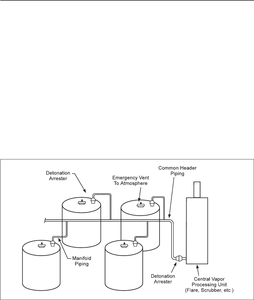
2.10.3.4 Where an explosion isolation system is needed, provide FM Approved detonation arresters as follows
(see Figure 1):
A. At each tank, in the piping connecting it to the vapor recovery system.
B. At the end of the manifold immediately upstream of the feed nozzle for any vapor processing equipment;
for example, incinerators and scrubbers.
Note: Detonation arresters may not be appropriate in systems where powders are handled or added on a
regular basis. The arrester could become plugged and fail to handle normal in-and-out breathing.
2.10.3.5 Provide detonation arresters with temperature sensors on each side, and as close as possible to
the face of the arresting element. Arrange the sensor to automatically close valves or initiate other actions that
will eliminate the possibility of a stabilized flame burning on the arrester element. Do not locate the sensor
in a thermowell that will delay its response. If the sensor is to be a metal-sheathed thermocouple, it must be
of small diameter (e.g., 1/4 in. [6 mm]), and must be inserted bare through a suitable packing gland.
2.10.3.6 Within 120 pipe diameters of the detonation arrester, install piping of equal or smaller diameter than
the detonation arrester.
Fig. 1. Manifolded tanks
Outdoor Ignitable Liquid Storage Tanks 7-88
FM Global Property Loss Prevention Data Sheets Page 13
©2020 Factory Mutual Insurance Company. All rights reserved.

Figures 2 and 3 show pipe sizing around detonation arrestors to meet this criteria.
2.10.3.7 Where conditions of operation will significantly exceed approximately atmospheric pressure and
temperature, specifically test detonation arresters under the actual operating conditions. Detonation arresters
are capable of successfully stopping detonation fronts only in systems initially at approximately atmospheric
pressure and temperature.
2.10.3.8 Install detonation arresters where they will be easily accessible for maintenance and inspection.
2.10.3.9 Install vapor-collection system piping in accordance with ASME B31.3, Chemical Plant and Petroleum
Refinery Piping, or international equivalent, designed for a maximum allowable working pressure of 150 psig
(10 barg).
2.10.3.10 Provide the flow capacity in common portions of manifolded vapor collection piping for the maximum
flow of all vents connected to that portion of the system.
2.10.3.11 Consider insulation and/or heat tracing of the system and arrester in cold climates where freezing
or condensation of the vapor is possible. The heat tracing must be kept below the accepted operating range
of the arrester.
2.11 Asphalt Tanks
In addition to the other criteria applying to outdoor tanks, apply the following to asphalt tanks.
2.11.1 Ensure tank roofs are watertight.
2.11.2 Inspect tanks vents and the underside of the roof for accumulation of condensed material on a regular
basis and keep records of the inspection results.
2.11.3 Use tanks with weak seam roof (pressure relieving) construction per API 650 or similar.
2.11.4 Provide tanks with only one breather vent to minimize introduction of air into the vapor space.
2.11.5 Keep roof gauging and manway hatches closed to prevent unintended entry of air into the vapor space.
2.11.6 Use gauging hatches rather than manways when checking liquid level to minimize air entry into the
tank vapor space.
2.11.7 Do not use pressure-vacuum (conservation) vents because condensed materials could prevent
operation of the vent.
A. Where inerting of the vapor space is used, conservation vents will be needed.
B. Inject the inert gas below the vents to keep them free of accumulations.
C. Inspect the vents on a regular basis and keep records of the inspection results.
Fig. 2. Required pipe sizing if detonation arrester is smaller than nearby piping
Fig. 3. Improper piping around detonation arrester
7-88 Outdoor Ignitable Liquid Storage Tanks
Page 14 FM Global Property Loss Prevention Data Sheets
©2020 Factory Mutual Insurance Company. All rights reserved.

2.11.8 Maintain tank liquid levels above any internal heating coils that could cause localized overheating,
cracking of the liquids generating light ends and creating condensed deposits on the roof. Provide a reliable
method to monitor tank liquid level.
2.11.9 Route supply piping for heating systems below the lowest liquid surface level or insulate the pipe with
a non-permeable material.
2.11.10 Monitor the tank temperature with sensors located where it will be representative of bulk liquid
temperature. Keep sensors away from tank walls, near submerged heating coils, or and below normal
operating levels.
2.11.11 Maintain tank temperatures at safe levels with the following considerations:
A. Keep temperatures at least 25°F (14°C) below the flash point (out of the flammable range).
B. Keep temperatures out of the range of 212°F to 265°F (100°C to 130°C) to avoid water condensation.
C. Temperatures above 350°F (177°C) encourage asphalt condensation on the roof surface. Deposit can
oxidize, generate heat and possibly autoignite above 375°F (190°C).
D. Provide inert gas blanketing (oxygen concentration of 3% to 5%) for tanks operating at 350°F to 450°F
(177°C to 232°C) to prevent oxidation of deposits.
E. Do not store materials at temperatures above 450°F (232°C) which can promote cracking and production
of light hydrocarbons and increase the likelihood of operation in the flammable range.
2.11.12 Do not allow entry of piping or any fixtures to or through the tank roof which would hinder deployment
of the weak seam roof in an explosion.
2.11.13 Inspect internal tank heating coils for cracks, corrosion, and other damage whenever the tank is
out of service and keep records of the inspection results.
2.11.14 Take precautions to safely oxidize pyrophoric deposits before taking the tank out of service (see
API RP 2016 for details).
2.11.15 Follow a written procedure for returning idled tanks to service that addresses at least the following:
A. Water accumulations that could boil on heating.
B. Residual product that may heat irregularly with localized overheating until the entire contents have
reached a uniform temperature.
C. Lighter products that might have been previously in the tank and addition of hot material that could
rapidly vaporize material and exceed vent capacity or cause the vapor space to enter the flammable range.
2.11.16 Develop an emergency response plan to address fire, explosion, and unexpected liquid release that
identifies the hazards, site layout, protection equipment, shutoff valves, etc., as well as specific response
to each type of event. Ensure outside responders are familiar with the response plan.
2.12 Operation and Maintenance
2.12.1. Implement a formal asset integrity program, as described in Data Sheet, 9-0 Asset Integrity. Additional
guidance on the inspection, testing and maintenance of these tanks can be found in API 653, Maintenance
and Testing for Atmospheric Storage Tanks, for all ignitable-liquid storage tanks.
2.12.2 Conduct monthly visual inspections of aboveground storage tanks. Focus on leaks, corrosion, condition
and maintenance of containment systems and ensuring drainage systems are clear and operable.
2.12.3 Conduct annual recorded inspections of tank vents, vent pipes, screens, and flame arresters, and
keep them free from obstructions that could prevent proper operation and possibly overpressurization of the
tank.
2.12.4 Conduct recorded inspections of detonation arresters in manifolded piping systems for damage and
accumulations of debris caused by polymerization, condensation, corrosion, etc., which could impair
operability. Replace damaged units (or repair if the damage does not affect their functionality) and remove
accumulations.
Outdoor Ignitable Liquid Storage Tanks 7-88
FM Global Property Loss Prevention Data Sheets Page 15
©2020 Factory Mutual Insurance Company. All rights reserved.

2.12.4.1 Conduct inspections at least quarterly during the first year and as experience dictates thereafter,
but at least annually (where practical).
2.12.4.2 Conduct inspection and testing in line with the guidance in Data Sheet 12-2, Vessels and Piping,
and 9-0, Asset Integrity. As a minimum, conduct external ultrasonic thickness inspections of the tank shell
every 5 years and conduct internal inspections at a minimum of every 10 years.
2.13 Repair, Reconditioning, and Abandonment
Prior to working on any tank that has contained ignitable liquids, take the following precautions as appropriate:
2.13.1 Drain all liquids from the tank, including residues. Disconnect fill and discharge pipes and install blind
flanges.
2.13.2 Purge ignitable liquid tanks with steam or warm air before repairs are made or before the tanks are
reused. Route displaced flammable vapor to a safe location. Avoid excessive pressure or vacuum. (See Data
Sheet 7-59, Inerting and Purging of Equipment.)
2.13.3 Use an FM Approved combustible gas detector to determine whether vapor has been eliminated.
Make additional tests at frequent intervals. Suspend work if flammable gas is detected.
2.13.4 Remove all remaining scale and sludge with nonferrous scrapers.
2.13.5 Fill the tank with an inert gas, such as carbon dioxide, or maintain positive continuous air movement
through the tank if cutting or welding torches are used on the outside of the tank. Do not cut or weld on rubber
lined tanks (rubber lined tanks are typically marked as such on the tank exterior).
2.13.6 Remove, underground ignitable liquid tanks that are no longer of any use. Prior to removal, inert the
tank. If removal of the tank is not possible, it may be left in place after doing the following:
A. Remove all of the liquid from the tank.
B. Purge the tank of flammable vapor.
C. Remove all suction, inlet, gauge, and vent lines.
D. Fill the tank with a solid inert material (e.g., sand, diatomaceous earth, perlite, etc.).
E. Cap all remaining underground piping.
F. Rebury the tank and fittings.
2.14 Human Factor
2.14.1 Establish emergency response plans in accordance with Data Sheet 7-32, Ignitable Liquid Operations.
2.14.2 Avoid hot work on or near all tank farms containing ignitable liquids or vapor. Where hot work is
required, follow the guidance in Data Sheet 10-3, Hot Work Management, in addition to the following:
A. The entire diked area should be considered a permit required area, even if the work is further from the
tank than the spacing guidelines in 10-3 Hot Work Management.
B. Isolate all open ends from tanks or equipment that will allow vapor to be liberated or sparks to enter
equipment (including breather vents).
C. Isolate, drain, and purge all equipment of ignitable liquid and flammable vapor, including pipes and
other pathways through which vapor or liquid can be transmitted to the tank, prior to the commencement
of work.
D. Conduct initial and continuous LEL detection, in the area the hot work will be conducted and all areas
where sparks or slag may fall.
7-88 Outdoor Ignitable Liquid Storage Tanks
Page 16 FM Global Property Loss Prevention Data Sheets
©2020 Factory Mutual Insurance Company. All rights reserved.

3.0 SUPPORT FOR RECOMMENDATIONS
3.1 Tank Construction
3.1.1 Atmospheric Tanks
Atmospheric tanks are used to store large quantities of liquids at pressures ranging from atmospheric to
1.0 psig (7 kPa). The following are the principal types of atmospheric tanks:
Cone roof tanks are the most widely used for ignitable liquid storage. They are usually welded and may
have either weak roof or weak shell-to-roof seams designed to fail preferentially to the tank shell in the event
of a fire or internal explosion. Their major disadvantage is the vapor loss caused by breathing (the normal
expansion and contraction of the tank contents with atmospheric changes).
Floating roof tanks are constructed with a roof floating on the liquid surface. The roof may be of double-deck
or pontoon-type construction (Figures 4 and 5). By eliminating the vapor space, breathing losses become
negligible, and the fire and explosion hazard is greatly reduced. The seal provided between the roof edge and
the tank wall allows the roof to move freely within the shell. Drainage facilities are provided to prevent the
accumulation of water on the roof surface.
Covered floating roof tanks are similar in construction to cone roof tanks, except for a metal pan (or,
occasionally, a double or pontoon internal roof) that floats on the liquid surface (Figure 6). Since the floating
cover is protected from the weather, no provision for drainage or for rain or snow loading is required. Vents
are provided around the periphery of the tank.
Fig. 4. Open top double deck
Outdoor Ignitable Liquid Storage Tanks 7-88
FM Global Property Loss Prevention Data Sheets Page 17
©2020 Factory Mutual Insurance Company. All rights reserved.

Lifter or expansion roof tanks resemble cone roof tanks, except the entire roof assembly has limited freedom
to move up and down within the shell. A vapor-tight liquid seal, which maintains a slight pressure on the
contents of the tank, provides a seal between the roof assembly and the shell. The moving roof minimizes
normal breathing losses. An expansion roof tank is occasionally used with a group of fixed roof tanks to take
up their composite vapor change.
Breather roof tanks are used where the liquid storage is not frequently disturbed. The horizontal flexible
diaphragm, or roof, is attached to the top edge of the tank shell and maintains a variable vapor space by
moving up and down. The roof, by confining the vapor, exerts a slight pressure upon the liquid, reducing
evaporation losses.
Vapordome tanks employ a dome containing a plastic diaphragm, which is free to move with the expansion
of vapor in the tank. This is an effective method of reducing vapor loss from the top of the tank.
Cylindrical tanks are used for small quantities of liquids. Heads may be dished or flat. The long axis may
be either horizontal or vertical and the tank buried or aboveground.
Fig. 5. Open top pontoon
Fig. 6. Pan-type covered tanks
7-88 Outdoor Ignitable Liquid Storage Tanks
Page 18 FM Global Property Loss Prevention Data Sheets
©2020 Factory Mutual Insurance Company. All rights reserved.

3.1.2 Manifolded Vents
Emission control systems on tanks vary and can include carbon bed adsorbers, scrubbers, condensers, and
incinerators. In some cases, the system could be handling vapor within the flammable range. If ignited (by
static or an incinerator flame) a flame front could propagate throughout with damaging results. Proper design
of the system can prevent such a situation.
The speed at which a flame front propagates within the piping is dependent on a number of factors. These
include the inherent system turbulence caused by bends, valves and fittings and the turbulence of the
combustion process itself. Transition from deflagration to detonation in pipe lengths of 50 to 100 diameters
are typically reported.
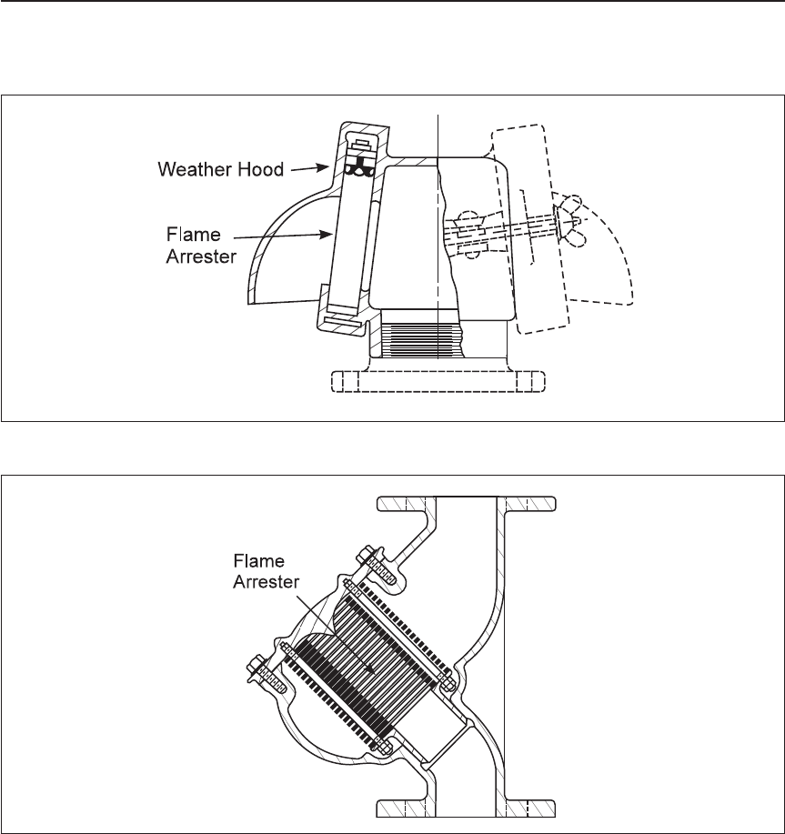
Flame-arresting devices (Figures 8 and 9) are typically used to stop deflagrations but are ineffective in
stopping detonations or in some cases ″fast″ deflagrations.
Other ineffective devices include rupture disks on elbows, or direction changes in the piping system. While
these may affect the pressure wave from a deflagraton, several other methods of explosion isolation are
available. These include fast-acting valves, rapid discharge extinguishing (blocking) systems and flame-front
diverters or backflash interrupters (Figure 10). None of these devices presently are FM Approved and
therefore are not discussed in detail. There is limited information available on installation criteria and
applicability limits. All are designed to interrupt deflagrations, not detonations.
Detonation arresters (Figure 7) are instead used to stop detonation fronts and are rated for a specific gas
or class of gases.
Detonation arresters are normally bidirectional being able to stop detonation fronts approaching from either
direction. Because it is difficult to ensure the direction of flame approach, unidirectional arresters are
therefore not preferred.
Additionally, flame arresters fitted with flanges at both ends are best in short piping runs. Long runs of piping
can allow a deflagration flame front to increase velocity, even up to a detonation front, causing the device
to fail.
Conservation vents are installed on many low pressure tanks to minimize the release of vapor during tank
idle times while permitting release of pressure or vacuum created during filling or emptying. They may be used
Fig. 7. Detonation arrester
Outdoor Ignitable Liquid Storage Tanks 7-88
FM Global Property Loss Prevention Data Sheets Page 19
©2020 Factory Mutual Insurance Company. All rights reserved.
in lieu of flame arresters. These devices are insufficient for stopping detonation propagation, and are not
acceptable alternatives to detonation arresters in manifolded piping systems.
3.1.3 Asphalt Tanks
Asphalt materials include a wide range of petroleum components and have auto-ignition temperatures
anywhere from 400°F to 900°F (204°C to 480°C).
Tanks are heated to near the flash point of the asphalt within, to keep the asphalt from solidifying. Heat coils
are located within the tank. The heat source can be direct-fired or via heat transfer fluid.
Loss history shows a disproportionate number of events involving tanks containing asphalt. Factors in these
events include the following:
A. Heating coils. Poorly maintained coils can leak, causing water release in the tank or back flow of asphalt
into the coils. Additionally, improperly controlled liquid levels in the tank can expose the heating coils with
localized heating and cracking of the hydrocarbon liquid resulting. The light hydrocarbons created can
move the vapor space into the flammable range.
Fig. 8. End-of-line flame arrester
Fig. 9. End-of-line flame arrester with pipe-away flange
7-88 Outdoor Ignitable Liquid Storage Tanks
Page 20 FM Global Property Loss Prevention Data Sheets
©2020 Factory Mutual Insurance Company. All rights reserved.

B. Material can condense inside vents, inside process lines and on tank roof surfaces. Condensed material
can be pyrophoric, iron sulfides, or carbonaceous. This many result in roof overloading or the creation
of “hot spots” in the normally oxygen-deficient tank vapor space. Sudden ingress of air can cause flaming
and a vapor-space explosion. When an inert atmosphere is purposely provided for the vapor space, care
must be taken to maintain about 3% to 5% oxygen concentration to allow slow oxidation of the
accumulated material.
C. Water can accumulate on the bottom and froth over on addition of hot materials. This can create the
potential for a steam explosion or overpressure situation within the tank.
D. Operating procedures are not always followed.
E. Asphalt storage tanks often are an integral component of asphalt processes and can lack spill
containment. Containment is important in preventing overflows and pool fires.
3.1.4 Protection
The basic protection for tank farms is hose streams along with adequate spacing and containment as specified
in Section 2.2.2. This will generally limit fire involvement to all tanks within a common dike or three large
tanks that are individually diked. For large tanks or tanks farms, manual fixed foam protection may be
appropriate. Fixed or portable foam-making equipment or water spray systems may be required to control fires
where the quantities of liquids stored or tank sizes are unusually large. Automatic foam systems should not
be seen as equivalent to adequate spacing and diking, selection of proper tank construction, or provision
of exposure protection.
Floating roof tanks are less susceptible to serious fire loss than cone roof tanks. Seal fires in floating roof
tanks can be readily extinguished with either portable extinguishing equipment or fixed foam extinguishing
systems, depending upon the size of the tank.
4.0 REFERENCES
4.1 FM Global
Data Sheet 1-11, Fire Following Earthquakes
Data Sheet 1-20, Protection Against Exterior Fire Exposure
Data Sheet 1-21, Fire Resistance of Building Assemblies
Data Sheet 1-57, Plastics in Construction
Fig. 10. Backflash interrupter
Outdoor Ignitable Liquid Storage Tanks 7-88
FM Global Property Loss Prevention Data Sheets Page 21
©2020 Factory Mutual Insurance Company. All rights reserved.

Data Sheet 2-0, Installation Guidelines for Automatic Sprinklers
Data Sheet 4-5, Portable Extinguishers
Data Sheet 4-12, Foam-Water Sprinkler Systems
Data Sheet 5-1, Electrical Equipment in Hazardous (Classified) Locations
Data Sheet 5-8, Static Electricity
Data Sheet 6-11, Thermal and Regenerative Thermal Oxidizers
Data Sheet 7-14, Fire Protection for Chemical Plants
Data Sheet 7-29, Ignitable Liquid Storage in Portable Containers
Data Sheet 7-32, Ignitable Liquid Operations
Data Sheet 7-43/17-2, Process Safety
Data Sheet 7-49, Emergency Venting of Vessels
Data Sheet 7-55, Liquefied Petroleum Gas
Data Sheet 7-59, Inerting and Purging of Tanks, Process Vessels, and Equipment
Data Sheet 7-78, Industrial Exhaust Systems
Data Sheet 7-83, Drainage and Contaiment Systems for Ignitable Liquids
Data Sheet 10-3, Hot Work Management
4.2 Others
American Petroleum Institute (API). API 12P, Fiberglass Reinforced Plastic Tanks.
American Petroleum Institute, API 620, Design and Construction of Large, Welded, Low-Pressure Storage
Tanks, Tenth Edition, 2002.
American Petroleum Institute, API 650, Welded Steel Tanks for Oil Storage, Tenth Edition, 1998.
American Petroleum Institute (API). ANSI/API 651, Cathodic Protection of Aboveground Petroleum Storage
Tanks, Second edition, 1997.
American Petroleum Institute (API). API 653, Tank Inspection, Repair, Alteration, and Reconstruction.
American Petroleum Institute, API 2000, Venting Atmospheric and Low Pressure Storage Tanks, Fifth edition,
1998.
American Petroleum Institute (API). API Recommended Practice 2016, Guidelines and Procedures for
Entering and Cleaning Petroleum Storage Tanks.
American Society of Mechanical Engineers (ASME), Boiler and Pressure Code, Section VIII, Unfired Pressure
Vessels, latest edition.
American Society of Mechanical Engineers (ASME), B31.3, Chemical Plant and Petroleum Refinery Piping,
latest edition.
ASTM International (ASTM). ASTM D3299, Standard Specification for Filament Wound Glass Fiber
Reinforced Thermoset Resin Chemical Resistant Tanks.
ASTM International (ASTM). ASTM D4097, Standard Specification for Contact Molded Glass Fiber Reinforced
Thermoset Resin Chemical Resistant Tanks.
ASTM International, ASTM D4206, Standard Test Method for Sustained Burning of Liquid Mixtures Using
the Small Scale Open-Cup Apparatus, 2001.
ASTM International (ASTM). ASTM E 119, Standard Test Methods for Fire Tests of Building Construction
and Materials.
7-88 Outdoor Ignitable Liquid Storage Tanks
Page 22 FM Global Property Loss Prevention Data Sheets
©2020 Factory Mutual Insurance Company. All rights reserved.

European Committee for Standardization. EN 12285, Part 1, Workshop Fabricated Steel Tanks - Horizontal
Cylindrical Single and Double Skin Tanks for Underground Storage of Flammable and Non-Flammable Water
Polluting Liquids.
European Committee for Standardization. EN 12285, Part 2, Workshop Fabricated Steel Tanks - Horizontal
Cylindrical Single and Double Skin Tanks forAboveground Storage of Flammable and Non-Flammable Water
Polluting Liquids.
European Committee for Standardization. EN 13121, GRP Tanks and Vessels for Use Aboveground.
European Committee for Standardization. EN 14015, Specification for Design and Manufacture of Site Built,
Vertical, Cylindrical, Flat-Bottomed, Aboveground, Welded, Steel Tanks for the Storage of Liquids at Ambient
Temperatures and Above.
European Committee for Standardization. S.I. No. 116/2003, European Communities (Classification,
Packaging, Labeling and Notification of Dangerous Substances) Regulations.
International Standards Organization, ISO 2592, Determination of flash and fire points \M Cleveland open
cup method, 2000.
National Association of Corrosion Engineers, NACE RP-0169, Control of External Corrosion on Underground
or Submerged Metallic Piping Systems.
National Association of Corrosion Engineers, NACE RP-0285, Corrosion Control of Underground Storage
Tanks System by Cathodic Protection.
National Fire Protection Agency (NFPA). NFPA 11, Standard for Low, Medium and High Expansion Foam
(2005).
National Fire Protection Agency (NFPA). NFPA 30, Flammable and Combustible Liquids Code (2003).
National Fire Protection Agency (NFPA). NFPA 70, National Electric Code.
National Fire Protection Agency (NFPA). NFPA 704, Standard System for the Identification of the Hazards
of Materials for Emergency Response
Underwriters Laboratories (UL). UL 58, Standard for Steel Underground Tanks for Flammable and
Combustible Liquids.
Underwriters Laboratories (UL). UL 142, Standard for Steel Aboveground Tanks for Flammable and
Combustible Liquids.
Underwriters Laboratories (UL). UL 1316, Standard for Glass Fiber Reinforced Plastic Underground Storage
Tanks.
Underwriters Laboratories (UL). UL 2080, Fire Resistant Tanks for Flammable and Combustible Liquids.
Underwriters Laboratories (UL). UL 2085, Protected Aboveground Tanks for Flammable and Combustible
Liquids.
U.S. Code of Federal Regulations, 33 CFR, Part 154, Appendix A, Guidelines for Detonation Flame Arresters.
U.S. Code of Federal Regulations, 49 CFR, Chapter I, Subchapter C, Parts 171 180 Department of
Transportation, Hazardous Materials Regulations.
APPENDIX A GLOSSARY OF TERMS
Conservation Vents: These devices have both vacuum and pressure relief capacity. Vents usually open
when the positive or neg ative pressure in the tank reaches
3
⁄4 to 1 in. water column (185 to 250 Pa). They
are normally closed and vent pipes equipped with conservation vents do not need flame arresters. The
velocity through the openings is normally sufficient to prevent flashback. A typical conservation vent is shown
in Figure 11.
FM Approved: References to ″FM Approved″ in this data sheet mean the product or service has satisfied
the criteria for FM Approval. Refer to the Approval Guide, an online resource of FM Approvals, for a complete
listing of products and services that are FM Approved.
Outdoor Ignitable Liquid Storage Tanks 7-88
FM Global Property Loss Prevention Data Sheets Page 23
©2020 Factory Mutual Insurance Company. All rights reserved.

Ignitable Liquid: Any liquid or liquid mixture that is capable of fueling a fire, including flammable liquids,
combustible liquids, inflammable liquids, or any other term for a liquid that will burn. An ignitable liquid is a
liquid that has a fire point.
Listed: Equipment or materials included in a list published by an organization that maintains periodic
inspection of production of listed equipment or materials and whose listing states that either the equipment
or material meets appropriate designated standards or has been tested and found suitable for a specified
purpose.
Roof, external floating: A roof that sits directly on the liquid surface, usually on pontoons with a seal attached
to the roof perimeter to cover the annular space between the roof and the shell. Design criteria are in API
650, Appendix C. This type has inherent buoyancy and are difficult, though not impossible, to sink.
Roof, internal floating: A roof similar to the external floater but with a fixed roof above, intended for weather
protection or quality assurance. The internal floater is often a simple pan or plastic membrane floating directly
on the liquid surface with little or no inherent buoyancy and is subject to sinking. Design criteria are in API
650, Appendix H. Pontoon type roofs similar or identical to external floaters are possible but not common.
Unless the internal floater has the inherent buoyancy of a pontoon type, treat the tank as a cone roof tank.
Stable liquid: Any liquid not defined as unstable.
Tank, aboveground: A tank that is installed above grade, at grade, or below grade without backfill.
Tank, atmospheric: A storage tank that has been designed to operate at pressures from atmospheric through
a gauge pressure of 1 psig (0.07 bar) measured at the top of the tank.
Tank, double-skinned: A term used in European Union (EN) standards for secondary containment tanks.
Tank, floating roof: An atmospheric tank intended for storage of high vapor pressure liquids such as crude
oil and gasoline with vapor pressure exceeding 15 psig (1 barg) with a roof floating on the liquid surface.
(Floating roof tanks are not covered by this standard.) Design in accordance with the criteria in API 650,
Appendix C or H, or other recognized equivalent standard.
Tank, low-pressure: A storage tank designed to withstand an internal pressure of more than 1 psig (0.07
barg) but not more than 15 psig (1 barg) measured at the top of the tank.
Fig. 11. Typical conservation vent
7-88 Outdoor Ignitable Liquid Storage Tanks
Page 24 FM Global Property Loss Prevention Data Sheets
©2020 Factory Mutual Insurance Company. All rights reserved.

Tank, portable: Any closed vessel having a liquid capacity over 60 gal (230 L) and not intended for fixed
installation. This includes intermediate bulk containers (IBCs) as defined and regulated by the U.S.
Department of Transportation in CFR Title 49, Part 178, subpart N, and the United Nations Recommendations
on the Transport of Dangerous Goods, chapter 6.5.
Tank, protected aboveground: An aboveground storage tank that is listed in accordance with UL 2085,
Standard for Protected Aboveground Tanks for Flammable and Combustible Liquids, or an equivalent test
procedure that consists of a primary tank provided with protection from physical damage and fire-resistive
protection from exposure to a high-intensity liquid pool fire.
Tank, secondary containment: A tank that has an inner and outer wall with an interstitial space (annulus)
between the walls and that has a means for monitoring the interstitial space for a leak.
Tank, storage: Any vessel having a liquid capacity that exceeds 60 gal (230 L), is intended for fixed
installation, and is not used for processing.
United Nations Recommendations on the Transport of Dangerous Goods: Model Regulations directed
at providing safe packaging criteria but only related to the transport of all types of dangerous solids, liquids,
and gases. Hazard class 3 addresses ignitable liquids.
Unstable liquid: A liquid that, in the pure state or as commercially produced or transported, will vigorously
polymerize, decompose, undergo condensation reaction, or become self-reactive under conditions of shock,
pressure, or temperature. A liquid with an NFPA instability hazard rating of 2 or greater in accordance with
NFPA 704, Standard System for the Identification of the Hazards of Materials for Emergency Response.
Vent, normal: Pressure relief opening on a tank to permit the intake and discharge of air during emptying
and filling operations and to permit expansion and contraction of vapor due to temperature changes.
Sometimes called breather vent.
Vent, emergency relief: Pressure relief opening on a tank to prevent overpressurizing the tank in the event
of fire exposure.
Wall, combustible: A wall made of any combustible material, including overhanging wood eaves, any metal
faced plastic insulated sandwich panels that are not FM Approved, and any wall with single pane, annealed
(not tempered) glass windows. Increase separation by 25% for asphalt-coated metal walls.
Wall, noncombustible: Materials include FM Approved Class 1 insulated, steel, or aluminum faced sandwich
panels with thermoset plastic insulation; EIFS assemblies having noncombustible insulation and gypsum
board sheathing, and aluminum or steel panels that are uninsulated or insulated with noncombustible
insulation such as glass fiber, mineral wool, or expanded glass. It also includes cementitious panels or
shingles over steel or wood. There can be no overhanging wood eaves. Any windows should be multi-pane
or tempered glass.
Wall, fire-rated: The wall should meet the required fire rating per FM Global Loss Prevention Data Sheet
1-21, Fire Resistance of Building Assemblies. Any openings should be protected with a comparably fire-rated
door. Any windows should be fire rated to match the rating of the wall.
Weak seam roof (weak shell-to-roof joint construction): The attachment of the roof to the shell forms a
frangible joint that, in the case of excessive internal pressure, will rupture before rupture occurs in the tank
shell joints or the shell-to-bottom joint. Design criteria can be found in UL 142 or API 650.
APPENDIX B DOCUMENT REVISION HISTORY
The purpose of this appendix is to capture the changes that were made to this document each time it was
published. Please note that section numbers refer specifically to those in the version published on the date
shown (i.e., the section numbers are not always the same from version to version).
October 2020. Interim revision. The following changes were made:
A. Updated guidance on inhibitors requiring oxygen to maintain activity (to reflect the guidance in Data
Sheet 7-59, Inerting and Purging of Tank, Process Vessels, and Equipment).
B. Updated outdoor storage, high flash point liquid guidance to align with Data Sheet 7-32, Ignitable Liquid
Operations.
April 2020. This document has been completely revised. The following major changes were made:
Outdoor Ignitable Liquid Storage Tanks 7-88
FM Global Property Loss Prevention Data Sheets Page 25
©2020 Factory Mutual Insurance Company. All rights reserved.

A. Changed title (from Ignitable Liquid Storage Tanks)toOutdoor Ignitable Liquid Storage Tanks.
B. Moved guidance for indoor tanks to Data Sheet 7-32, Ignitable Liquid Operations.
C. Removed guidance for silicon and other atypical liquids; see Data Sheet 7-32, Ignitable Liquid
Operations.
D. Updated recommended separation distances for outdoor storage tanks.
E. Updated the guidance for impounding in lieu of containment.
F. Made guidance for secondary containment apply to all liquids, regardless of flashpoint.
G. Reorganized the document to provide a format that is consistent with other data sheets.
H. Updated the definition for very high flash point liquids to align with Data Sheet 7-32, Ignitable Liquid
Operations.
April 2018. Interim revision. Lowered the flash point threshold of very high flashpoint liquids from 500°F
(260°C) to 450°F (232°C) to be consistent with other ignitable liquid data sheets.
January 2018. Interim revision. Clarification was made to Table 4 to be consistent with DataSheet 1-22,
Maximum Foreseeable Loss
October 2015. Major revisions were focused on the arrangement and protection of indoor tanks, although
other aspects of the data sheet were also modified. The following major changes have been made:
A. Changed the name of the data sheet from ″Flammable Liquid Storage Tanks″ to ″Ignitable Liquid
Storage Tanks.″
B. Reorganized the document where necessary to provide a format that is consistent with other data
sheets.
C. Replaced references to ″flammable″ and ″combustible″ liquid with ″ignitable” liquid throughout the
document.
D. Added recommendations for the storage of liquids with closed-cup flash points at or above 500°F
(260°C) and several other atypical liquids.
E. Added recommendations related to the protection of structural steel.
F. Clarified recommendations for containment and emergency drainage for indoor tanks.
G. Clarified recommendations relative to the use of secondary containment (i.e., double-walled) tanks,
including a revised capacity limit (12,000 gal [45 m
3
] increased to 30,000 gal [113 m
3
]).
H. Revised the guidance for protection against flooding for consistency with Data Sheet 1-40, Flood.
I. Modified automatic sprinkler and special protection recommendations for indoor tanks.
J. Added recommendations related to training and human element.
K. Removed indoor tank liquid quantity limitations, provided the tank and supporting systems are
adequately designed and protected in accordance with this data sheet.
October 2014. Interim revision. Minor editorial changes were made.
October 2011. The reference in Table 10, note 1 was corrected from 2.2.2-5 to 2.1.2-5.
September 2010. Changes were made in Table 3, Spacing for Flammable Liquid Tank Containment Dikes.
March 2009. Minimum spacing requirements in Table 2, Spacing for Flammable Liquid Storage Tanks and
Loading/Unloading Stations, and in Table 3, Spacing for Flammable Liquid Tank Containment Dikes, were
modified.
May 2008. Minor editorial changes were made for this revision.
January 2008. Minor editorial changes were made for this revision.
May 2007. Corrections were made to Table 2.
April 2007. Minor editorial changes were made to January 2007 version.
7-88 Outdoor Ignitable Liquid Storage Tanks
Page 26 FM Global Property Loss Prevention Data Sheets
©2020 Factory Mutual Insurance Company. All rights reserved.

January 2007. The following changes were made:
• Removed the recommendation against bottom connections on FRP tanks to be consistent with referenced
standards.
• Extended the recommendation for containment to all tanks with flash points below 200°F (93°C). Previously,
no containment was required for tanks of less than 15,000 gal (57 m
3
) except to protect buildings.
• Simplified the spacing and diking recommendations.
• Upgraded the recommendation for indoor tanks, including automatic fire and leak-detection systems.
• Added recommendations for secondary containment tanks.
• Eliminated the exemption to the recommendations for cutoffs for small fuel oil tanks serving heating
appliances.
• Added recommendations for IBCs when supplying flammable liquids to a process.
• Added earthquake recommendations, including seismic shutoffs for indoor tanks.
• Added section on asphalt storage tanks.
• Added recommendations for monitoring tanks during fill operations, level-gauging, and high-level alarms
to an attended location.
• Moved information on carbon disulfide to Data Sheet 7-23N, Hazardous Chemical Data.
• Added section on asphalt storage tanks.
• Added recommendations for monitoring tanks during fill operations, level-gauging, and high-level alarms
to an attended location.
• Moved information on carbon disulfide to Data Sheet 7-23N, Hazardous Chemical Data.
September 2000. This revision of the document has been reorganized to provide a consistent format.
October 1994. Added information on manifold vents in systems, and detonation arrestors.
July 1976. Miscellaneous revisions and updating.
May 1971. Miscellaneous revisions and updating.
November 1967. Updated and consolidated material from handbook.
1959. Original guideline in Factory Mutual handbook of Industrial Loss Prevention.
APPENDIX C JOB AIDS
C.1 Calculating Emergency Venting Requirements (API 2000)
Where tanks are operating at pressures greater than 1 psig (7 kPa) and having exposed wetted areas greater
than 2800 ft
2
(260 m
2
), the following equations can be used to calculate the emergency venting capacity:
V = 1107 A
0.82
(English)
V = 220 A
0.82
(metric)
Where:
V = hexane vent requirement, ft
3
/hr or m
3
/hr (at standard conditions)
A = exposed wetted surface, ft
2
or m
2
If the stored liquid is something other than hexane, then the emergency venting capacity can be adjusted
using the following equations:
V’ = V 1337 / L (M)
1/2
V’=V3110/L(M)
1/2
Where:
Outdoor Ignitable Liquid Storage Tanks 7-88
FM Global Property Loss Prevention Data Sheets Page 27
©2020 Factory Mutual Insurance Company. All rights reserved.

V = hexane vent requirement from Table 5, ft
3
/hr or m
3
/hr.
V’ = stored liquid vent requirement, ft
3
/hr or m
3
/hr.
L = latent heat of vaporization of stored liquid, Btu/lb or kJ/kg.
M = molecular weight of stored liquid, no units.
Table 7 lists L (M)1/2 for a number of common liquids. Data on other liquids can be found in most handbooks.
Table 7. Values for L (M)
1/2
for Other Common Liquids
Chemical L (M)
1/2
Chemical L (M)
1/2
English
(1)
Metric
(1)
English
(1)
Metric
(1)
Acetic Acid 1350 3140 Ethyl acetate 1477 3436
Acetic Anhydride 1792 4168 Ethyl alcohol 2500 5815
Acetone 1708 3973 Ethyl chloride 1340 3117
Acetonitrile 2000 4652 Ethylene
dichloride
1363 3170
n-Amyl alcohol 2025 4710 Ethyl ether 1310 3047
iso-Amyl alcohol 1990 4629 Furan 1362 3168
Aniline 1795 4012 Furfural 1962 4564
Benzene 1493 3473 Gasoline 1370–1470 3187–3419
n-Butyl acetate 1432 3331 n-Heptane 1383 3217
n-Butyl alcohol 2185 5082 n-Hexane 1337 3110
iso-Butyl alcohol 2135 4966 Methyl alcohol 2680 6234
Carbon disulfide 1310 3047 Methyl ethyl
ketone
1623 3775
Chlorobenzene 1422 3308 n-Octane 1412 3284
Cyclohexane 1414 3289 n-Pentane 1300 3024
Cyclohexanol 1953 4543 n-Propyl acetate 1468 3415
Cyclohexanone 1625 3780 n-Propyl alcohol 2295 5338
o-Dichlorobenzene 1455 3384 iso-Propyl alcohol 2225 5175
cis-
Dichloroethylene
1350 3140 Tetrahydrofuran 1428 3322
Diethylamine 1403 3263 Toluene 1500 3489
Dimethyl
acetamide
1997 4645 o-Xylene 1538 3577
Dimethyl amine 1676 3898
(1)
L (heat of vaporization) in Btu/lb or kJ/kg
7-88 Outdoor Ignitable Liquid Storage Tanks
Page 28 FM Global Property Loss Prevention Data Sheets
©2020 Factory Mutual Insurance Company. All rights reserved.
