
Zynq UltraScale+ MPSoC
Soware Developer Guide
UG1137 (v2022.2) November 2, 2022
See all versions
of this document
Xilinx is creating an environment where employees, customers, and
partners feel welcome and included. To that end, we’re removing non-
inclusive language from our products and related collateral. We’ve
launched an internal initiative to remove language that could exclude
people or reinforce historical biases, including terms embedded in our
software and IPs. You may still find examples of non-inclusive
language in our older products as we work to make these changes and
align with evolving industry standards. Follow this link for more
information.

Table of Contents
Chapter 1: About This Guide.....................................................................................6
Introduction................................................................................................................................. 6
Intended Audience and Scope of this Document....................................................................7
Prerequisites................................................................................................................................ 7
Chapter 2: Programming View of Zynq UltraScale+ MPSoC
Devices............................................................................................................................. 9
Hardware Architecture Overview.............................................................................................. 9
Boot Process.............................................................................................................................. 12
Virtualization..............................................................................................................................15
System Level Reset Requirements.......................................................................................... 15
Security....................................................................................................................................... 16
Safety and Reliability.................................................................................................................19
Memory Overview for APU and RPU Executables.................................................................22
Chapter 3: Development Tools.............................................................................. 24
Vivado Design Suite.................................................................................................................. 24
Vitis Unified Software Platform............................................................................................... 26
Arm GNU Tools.......................................................................................................................... 28
Device Tree Generator..............................................................................................................29
PetaLinux Tools..........................................................................................................................29
Linux Software Development using Yocto............................................................................. 30
Chapter 4: Software Stack....................................................................................... 33
Bare Metal Software Stack....................................................................................................... 33
Linux Software Stack.................................................................................................................36
Third-Party Software Stack.......................................................................................................41
Chapter 5: Software Development Flow.......................................................... 42
Bare Metal Application Development.....................................................................................43
Application Development Using PetaLinux Tools................................................................. 45
Linux Application Development Using Vitis........................................................................... 45
UG1137 (v2022.2) November 2, 2022 www.xilinx.com
Zynq UltraScale+ MPSoC: Software Developers Guide 2

Chapter 6: Software Design Paradigms........................................................... 50
Frameworks for Multiprocessor Development......................................................................50
Symmetric Multiprocessing (SMP).......................................................................................... 51
Asymmetric Multiprocessing (AMP)........................................................................................52
Chapter 7: System Boot and Configuration................................................... 56
Boot Process Overview.............................................................................................................56
Boot Flow....................................................................................................................................56
Boot Image Creation.................................................................................................................58
Boot Modes................................................................................................................................60
Detailed Boot Flow.................................................................................................................... 65
Disabling FPD in Boot Sequence............................................................................................. 68
Setting FSBL Compilation Flags...............................................................................................68
FSBL Build Process.................................................................................................................... 72
Using the Ethernet-Based Recovery Tool...............................................................................97
Chapter 8: Security Features..................................................................................99
Boot Time Security.................................................................................................................... 99
Bitstream Authentication Using External Memory............................................................. 110
Run-Time Security................................................................................................................... 113
Trusted Firmware-A................................................................................................................ 113
FPGA Manager Solution......................................................................................................... 116
Xilinx Memory Protection Unit...............................................................................................118
Xilinx Peripheral Protection Unit........................................................................................... 119
System Memory Management Unit......................................................................................119
A53 Memory Management Unit............................................................................................ 120
R5 Memory Protection Unit....................................................................................................120
TrustZone................................................................................................................................. 120
Chapter 9: Platform Management.................................................................... 121
Platform Management in PS..................................................................................................121
Wake Up Mechanisms............................................................................................................ 124
Platform Management for Memory......................................................................................125
DDR Controller.........................................................................................................................125
Platform Management for Interconnects............................................................................125
PMU Firmware......................................................................................................................... 126
Chapter 10: Platform Management Unit Firmware................................ 127
UG1137 (v2022.2) November 2, 2022 www.xilinx.com
Zynq UltraScale+ MPSoC: Software Developers Guide 3

Features....................................................................................................................................127
PMU Firmware Architecture...................................................................................................128
Execution Flow.........................................................................................................................129
Handling Inter-Process Interrupts in PMU firmware......................................................... 131
PMU Firmware Modules.........................................................................................................135
Error Management (EM) Module.......................................................................................... 138
Power Management (PM) Module........................................................................................144
Scheduler..................................................................................................................................145
Safety Test Library...................................................................................................................145
CSU/PMU Register Access......................................................................................................146
Timers....................................................................................................................................... 147
Configuration Object.............................................................................................................. 150
PMU Firmware Loading Options........................................................................................... 152
PMU Firmware Usage............................................................................................................. 158
PMU Firmware Memory Layout and Footprint....................................................................164
Dependencies.......................................................................................................................... 166
Chapter 11: Power Management Framework.............................................167
Introduction............................................................................................................................. 167
Zynq UltraScale+ MPSoC Power Management Overview...................................................169
Power Management Framework Overview......................................................................... 173
Using the API for Power Management.................................................................................186
XilPM Implementation Details...............................................................................................193
Linux......................................................................................................................................... 196
Trusted Firmware-A (TF-A)..................................................................................................... 213
PMU Firmware......................................................................................................................... 216
Chapter 12: Reset........................................................................................................ 219
System-Level Reset................................................................................................................. 219
Block-Level Resets...................................................................................................................219
Application Processing Unit Reset........................................................................................ 220
Real Time Processing Unit Reset...........................................................................................221
Full Power Domain Reset....................................................................................................... 221
Warm Restart...........................................................................................................................221
Supported Use Cases..............................................................................................................225
Chapter 13: High-Speed Bus Interfaces......................................................... 248
USB 3.0......................................................................................................................................248
Gigabit Ethernet Controller....................................................................................................251
UG1137 (v2022.2) November 2, 2022 www.xilinx.com
Zynq UltraScale+ MPSoC: Software Developers Guide 4

PCI Express...............................................................................................................................254
Chapter 14: Clock and Frequency Management....................................... 259
Changing the Peripheral Frequency.....................................................................................259
Chapter 15: Target Development Platforms................................................261
QEMU........................................................................................................................................261
Boards and Kits........................................................................................................................261
Chapter 16: Boot Image Creation...................................................................... 262
Appendix A: Libraries............................................................................................... 263
Appendix B: Additional Resources and Legal Notices........................... 264
Xilinx Resources.......................................................................................................................264
Documentation Navigator and Design Hubs...................................................................... 264
References................................................................................................................................264
Revision History.......................................................................................................................267
Please Read: Important Legal Notices................................................................................. 267
UG1137 (v2022.2) November 2, 2022 www.xilinx.com
Zynq UltraScale+ MPSoC: Software Developers Guide 5

Chapter 1
About This Guide
Introduction
This document provides the soware-centric informaon required for designing and developing
system soware and applicaons for the Xilinx
®
Zynq
®
UltraScale+™ MPSoCs. The
Zynq UltraScale+ MPSoC family has dierent products, based upon the following system
features:
• Applicaon processing unit (APU):
○ Dual or Quad-core Arm
®
Cortex
®
-A53 MPCore
○ CPU frequency up to 1.5 GHz
• Real-me processing unit (RPU):
○ Dual-core Arm Cortex
®
-R5F MPCore
○ CPU frequency up to 600 MHz
• Graphics processing unit (GPU):
○ Arm Mali-400 MP2
○ GPU frequency up to 667 MHz
• Video codec unit (VCU):
○ Simultaneous Encode and Decode through separate cores
○ H.264 high prole level 5.2 (4Kx2K-60)
○ H.265 (HEVC) main, main10 prole, level 5.1, high Tier, up to 4Kx2K-60 rate
○ 8 and 10-bit encoding
○ 4:2:0 and 4:2:2 chroma sampling
For more details, see the Zynq UltraScale+ MPSoC Product Table and the Product Advantages.
Chapter 1: About This Guide
UG1137 (v2022.2) November 2, 2022 www.xilinx.com
Zynq UltraScale+ MPSoC: Software Developers Guide 6

Intended Audience and Scope of this
Document
The purpose of this guide is to enable soware developers and system architects to become
familiar with:
• Xilinx soware development tools.
• Available programming opons.
• Xilinx soware components that include device drivers, middleware stacks, frameworks, and
example applicaons.
• Plaorm management unit rmware (PMU rmware), Trusted Firmware-A (TF-A), OpenAMP,
PetaLinux tools, Xen Hypervisor, and other tools developed for the Zynq UltraScale+ MPSoC
device.
Prerequisites
This document assumes that you are:
• Experienced with embedded soware development
• Familiar with Armv7 and Armv8 architecture
• Familiar with Xilinx development tools such as the Vivado
®
Integrated Design Environment
(IDE), the Vis™ unied soware plaorm, compilers, debuggers, and operang systems.
This document includes the following chapters:
• Chapter 2: Programming View of Zynq UltraScale+ MPSoC Devices: Briey explains the
architecture of the Zynq UltraScale+ MPSoC hardware. Xilinx recommends you to go through
and understand each feature of this chapter.
• Chapter 3: Development Tools: Provides a brief descripon about the Xilinx soware
development tools. This chapter helps you to understand all the available features in the
soware development tools. It is recommended for soware developers to go through this
chapter and understand the procedure involved in building and debugging soware
applicaons.
• Chapter 4: Soware Stack: Provides a descripon of various soware stacks such as bare
metal soware, RTOS-based soware and the full-edged Linux stack provided by Xilinx for
developing systems with the Zynq UltraScale+ MPSoC device.
• Chapter 5: Soware Development Flow: Walks you through the soware development
process. It also provides a brief descripon of the APIs and drivers supported in the Linux OS
and bare metal.
Chapter 1: About This Guide
UG1137 (v2022.2) November 2, 2022 www.xilinx.com
Zynq UltraScale+ MPSoC: Software Developers Guide 7

• Chapter 6: Soware Design Paradigms: Helps you understand dierent approaches to develop
soware on the heterogeneous processing systems. Aer reading this chapter, you will have a
beer understanding of programming in dierent processor modes like symmetric mul-
processing (SMP), asymmetric mul-processing (AMP), virtualizaon, and a hybrid mode that
combines SMP and AMP.
• Chapter 7: System Boot and Conguraon: Describes the boong process using dierent
boong devices in both secure and non-secure modes.
• Chapter 8: Security Features: Describes the Zynq UltraScale+ MPSoC devices features you
can leverage to enhance security during applicaon boot- and run-me.
• Chapter 9: Plaorm Management: Describes the features available to manage power
consumpon, and how to control the various power modes using soware.
• Chapter 10: Plaorm Management Unit Firmware: Describes the features and funconality of
PMU rmware developed for Zynq UltraScale+ MPSoC device.
• Chapter 11: Power Management Framework: Describes the funconality of the Xilinx Power
Management Framework (PMF) that supports a exible power management control through
the plaorm management unit (PMU).
• Chapter 12: Reset: Explains the system and module-level resets.
• Chapter 13: High-Speed Bus Interfaces: Explains the conguraon ow of the high-speed
interface protocols.
• Chapter 14: Clock and Frequency Management: Briey explains the clock and frequency
management of peripherals in Zynq UltraScale+ MPSoC devices.
• Chapter 15: Target Development Plaorms: Explains about the dierent development
plaorms available for the Zynq UltraScale+ MPSoC device, such as quick emulators (QEMU),
and the Zynq UltraScale+ MPSoC boards and kits.
• Chapter 16: Boot Image Creaon: Describes Bootgen, a standalone tool for creang a
bootable image forZynq UltraScale+ MPSoC devices. Bootgen is included in the Vis soware
plaorm.
• Appendix A - Appendix K: Describe the available libraries and board support packages to help
you develop a soware plaorm.
• Appendix B: Addional Resources and Legal Noces: Provides links to addional informaon
that is cited throughout the document.
Chapter 1: About This Guide
UG1137 (v2022.2) November 2, 2022 www.xilinx.com
Zynq UltraScale+ MPSoC: Software Developers Guide 8

Chapter 2
Programming View of Zynq
UltraScale+ MPSoC Devices
The Zynq
®
UltraScale+™ MPSoC supports a wide range of applicaons that require
heterogeneous mulprocessing. Heterogeneous mulprocessing system consists of mulple
single and mul-core processors of diering types. It supports the following features:
• Mulple levels of security
• Increased safety
• Advanced power management
• Superior processing, I/O, and memory bandwidth
• A design approach, based on heterogeneous mulprocessing presents design challenges,
which includes:
○ Meeng applicaon performance requirements within a specied power envelope
○ Opmizing memory access within heterogeneous mulprocessing system
○ Providing low-latency, coherent communicaons between various processing engines
○ Managing and opmizing system power consumpon in all operaonal modes
Xilinx
®
provides comprehensive tools for hardware and soware development on the
Zynq UltraScale+ MPSoC, and various soware modules such as operang systems,
heterogeneous system soware, and security management modules.
The Zynq UltraScale+ MPSoC is a heterogeneous device that includes the Arm
®
Cortex
®
-A53,
high-performance, energy-ecient, 64-bit applicaon processor, and also the 32-bit Arm
Cortex
®
-R5F dual-core real-me processor.
Hardware Architecture Overview
The Zynq UltraScale+ MPSoCs provide power savings, programmable acceleraon, I/O, and
memory bandwidth. These features are ideal for applicaons that require heterogeneous
mulprocessing.
Chapter 2: Programming View of Zynq UltraScale+ MPSoC Devices
UG1137 (v2022.2) November 2, 2022 www.xilinx.com
Zynq UltraScale+ MPSoC: Software Developers Guide 9

The following gure shows the Zynq UltraScale+ MPSoC architecture with next-generaon
programmable engines for security, safety, reliability, and scalability.
Chapter 2: Programming View of Zynq UltraScale+ MPSoC Devices
UG1137 (v2022.2) November 2, 2022 www.xilinx.com
Zynq UltraScale+ MPSoC: Software Developers Guide 10

Figure 1: Zynq UltraScale+ MPSoC Device Hardware Architecture
RPU
256 KB
OCM
LPD-DMA
CSU
PMU
Processing System
Cortex-R5F
32 KB I/D
128 KB TCM
Cortex-R5F
32 KB I/D
128 KB TCM
4 x 1GE
APU
Cortex-A53
32 KB I/D
Cortex-A53
32 KB I/D
Cortex-A53
32 KB I/D
Cortex-A53
32 KB I/D
GIC
SCU
ACP 1 MB L2
GPU
Mali-400 MP2
64 KB L2
2 x USB 3.0
NAND x8
ONFI 3.1
2 x SD3.0/
eMMC4.51
Quad-SPI
x 8
2 x SPI
2 x CAN
2 x I2C
2 x UART
GPIOs
SYSMON
MIO
Central
Switch
FPD-DMA
VCU
H.264/H.265
PCIe
Gen4
DisplayPort
v1.2 x1, x2
2 x SATA
v3.0
PCIe Gen2
x1, x2, or x4
SHA3
AES-GCM
RSA
Processor
System
BPU
DDRC (DDR4/3/3L, LPDDR3/4)
Programmabl
e Logic
128 KB RAM
PL_LPD
HP
GIC
LLLP
LLLP
RGMII
ULPI
PS-GTR
SMMU/CCI
GFC
USB 3.0
SGMII
Low Power Switch
To ACP
Low Power Full Power
Battery
Power
32-bit/64-bit
64-bit
M S
128-bit
M S
LPD_PL HPCHPM
GTY
Quad
GTH
Quad
Interlaken
100G
Ethernet
ACE
DisplayPort
Video and
Audio Interface
M => AXI Master S => AXI Slave
X23704-021320
Chapter 2: Programming View of Zynq UltraScale+ MPSoC Devices
UG1137 (v2022.2) November 2, 2022 www.xilinx.com
Zynq UltraScale+ MPSoC: Software Developers Guide 11

The Zynq UltraScale+ MPSoC features are as follows:
• Cortex-R5F dual-core real-me processor unit (RPU)
• Arm Cortex-A53 64-bit quad/dual-core processor unit (APU)
• Mali-400 MP2 graphic processing unit (GPU)
• External memory interfaces: DDR4, LPDDR4, DDR3, DDR3L, LPDDR3, 2x Quad-SPI, and
NAND
• General connecvity: 2x USB 3.0, 2x SD/SDIO, 2x UART, 2x CAN 2.0B, 2x I2C, 2x SPI, 4x
1GE, and GPIO
• Security: Advanced Encrypon Standard (AES), RSA public key encrypon algorithm, and
Secure Hash Algorithm-3 (SHA-3)
• AMS system monitor: 10-bit, 1 MSPS ADC, temperature, voltage, and current monitor
• The processor subsystem (PS) has ve high-speed serial I/O (HSSIO) interfaces supporng the
protocols:
○ PCIe
®
: base specicaon, version 2.1 compliant, and Gen2x4
○ SATA 3.0
○ DisplayPort: Implements a DisplayPort source-only interface with video resoluon up to 4k
x 2k
○ USB 3.0: Compliant to USB 3.0 specicaon implemenng a 5 Gb/s line rate
○ Serial GMII: Supports a 1 Gb/s SGMII interface
• Plaorm Management Unit (PMU) for funcons that include power sequencing, safety,
security, and debug.
For more details, see the following secons of the Zynq UltraScale+ Device Technical Reference
Manual (UG1085): APU, RPU, PMU, GPU, and inter-processor interrupt (IPI).
Boot Process
The plaorm management unit (PMU) and conguraon security unit (CSU) manage and perform
the mul-staged boong process. You can boot the device in either secure or non-secure mode.
See Boot Process Overview or, see the Boot and Conguraon chapter of the Zynq UltraScale+
Device Technical Reference Manual (UG1085).
Boot Modes
You can use any of the following as the boot mode for boong from external devices:
Chapter 2: Programming View of Zynq UltraScale+ MPSoC Devices
UG1137 (v2022.2) November 2, 2022 www.xilinx.com
Zynq UltraScale+ MPSoC: Software Developers Guide 12

• Quad SPI ash memory (QSPI24, QSPI32)
• eMMC18
• NAND
• Secure Digital Interface Memory (SD0, SD1)
• JTAG
• USB
The bootROM does not directly support boong from SATA, Ethernet, or PCI Express (PCIe). The
boot security does not rely on, and is largely orthogonal to TrustZone (TZ). The bootROM
(running on the Plaorm Management Unit) performs the security resources management (for
example, key management) and establishes root-of-trust. It authencates FSBL, locks boot
security resources, and transfers chain-of-trust control to FSBL (either on APU or RPU).
To understand more about the boot process in the dierent boot modes, see the ‘Boot and
Conguraon’ chapter of the Zynq UltraScale+ Device Technical Reference Manual (UG1085).
QSPI24 and QSPI32
The QSPI boot mode supports the following:
• x1, x2, and x4 read modes for single Quad SPI ash memory (QSPI24) and x8 for dual QSPI
• Image search for MulBoot
• I/O mode is not supported in FSBL
Note: Single Quad-SPI memory (x1, x2 and x4) is the only boot mode that supports execute-in-place (XIP).
For addional informaon, see QSPI24 and QSPI32 Boot Modes.
eMMC18
The eMMC18 boot mode supports:
• FAT 16 and FAT 32 le systems for reading the boot images.
• Image search for MulBoot. The maximum number of searchable les as part of an image
search for MulBoot is 8,191.
For addional informaon, see eMMC18 Boot Mode.
NAND
The NAND boot supports the following:
• 8-bit widths for reading the boot images
• Image search for MulBoot
Chapter 2: Programming View of Zynq UltraScale+ MPSoC Devices
UG1137 (v2022.2) November 2, 2022 www.xilinx.com
Zynq UltraScale+ MPSoC: Software Developers Guide 13

For addional informaon, see NAND Boot Mode.
SD
The SD boot supported version is 3.0. This version supports:
• FAT 16/32 le systems for reading the boot images.
• Image search for MulBoot. The maximum number of searchable les as part of an image
search for MulBoot is 8,191.
For addional informaon, see SD Boot Mode.
JTAG
You can download any soware images needed for the PS and hardware images needed for the
PL using JTAG.
IMPORTANT! In JTAG mode, you can boot the Zynq UltraScale+ MPSoC in non-secure mode only.
For addional informaon, see JTAG Boot Mode.
Zynq UltraScale+ devices do not support JTAG accesses while the CPU cores are powered down
randomly by the soware running on the device.
In case of PetaLinux, these kernel conguraon opons are known to be incompable with the
JTAG debugger:
• CONFIG_PERF_EVENTS
• CONFIG_FREEZER
• CONFIG_SUSPEND
• CONFIG_PM
• CONFIG_CPU_IDLE
USB
USB boot mode supports USB 3.0. It does not support MulBoot, image fallback, or XIP. It
supports both secure and non-secure boot mode. It is not supported for systems without DDR.
USB boot mode is disabled by default. For addional informaon, see USB Boot Mode.
Chapter 2: Programming View of Zynq UltraScale+ MPSoC Devices
UG1137 (v2022.2) November 2, 2022 www.xilinx.com
Zynq UltraScale+ MPSoC: Software Developers Guide 14

Virtualization
Virtualizaon allows mulple soware stacks to run simultaneously on the same processor,
which enhances the producvity of the Zynq UltraScale+ MPSoC. The role of virtualizaon varies
from system to system. For some designers, virtualizaon allows the processor to be kept fully
loaded at all mes, saving power and maximizing performance. For others systems, virtualizaon
provides the means to paron the various soware stacks for isolaon or redundancy.
For more informaon, see System Virtualizaon in the Zynq UltraScale+ Device Technical Reference
Manual (UG1085).
The support for virtualizaon applies only to an implementaon that includes Arm excepon
level-2 (EL2). Armv8 supports virtualizaon extension to achieve full virtualizaon with near
nave guest operang systems performance. There are three key hardware components for
virtualizaon:
• CPU virtualizaon
• Interrupt virtualizaon
• System MMU for I/O virtualizaon
System Level Reset Requirements
The system-level reset term is used to describe the system or subsystem level resets. ‘System’
reset (dierent from system-level resets) is a specic type of system-level reset. The following
table provides summary of system-level resets, which are described in details in subsequent
secons.
Table 1: System-Level Resets
Reset Type Description
External POR The external POR reset is triggered by external pin assertion. There are a
number of software only registers which are not reset by the POR resets. At first
POR boot, a safety system (requiring HFT1 by PS & PL) can be configured such
that a subsequent POR only resets PS (and not PL).
Internal POR Internal POR reset can be triggered by software register write, or by safety
errors. With the exception of error status register (which are reset by external
POR, but not by internal POR), internal POR resets the same thing as external
reset does. Internal-POR cannot be guaranteed without silicon validation (due
to in-rush power concern), so internal-POR is for internal purpose unless
validated.
System Reset
System reset is to be able to reset system excluding debug logic. To simplify
system reset, there are few other things (xBIST, scan clear, power gating) which
are not reset by this reset. Also, boot mode information is not reset by system
reset. The system reset can be triggered by external pin (SRST), or software
register write, or by safety errors.
Chapter 2: Programming View of Zynq UltraScale+ MPSoC Devices
UG1137 (v2022.2) November 2, 2022 www.xilinx.com
Zynq UltraScale+ MPSoC: Software Developers Guide 15

Table 1: System-Level Resets (cont'd)
Reset Type Description
PS Only Reset The PS only reset is to reset the PS while the PL remains active. This reset can be
triggered by hardware error signals or by software register write. This reset is a
subset of system reset (excluding the PL reset). If the PS reset is triggered by an
error signal, then the error is also transmitted to the PL.
FPD Reset The FPD reset resets all of the FPD power domain. It can be triggered by errors
or software register write. If the FPD reset is triggered by an error signal, then
the error is also transmitted to LPD & PL.
RPU Reset The RPU Reset is to reset the RPU in case of errors. While each of the R5 core
can be independently reset, but in lockstep, only R5_0 needs to be reset to reset
both the R5 cores. This reset can be triggered by errors or software register
write.
Security
The increasing ubiquity of Xilinx devices makes protecng the intellectual property (IP) within
them as important as protecng the data processed by the device. As security threats have
increased, the range of security threats or potenal weaknesses that must be considered to
deploy secure products has grown as well.
The Zynq UltraScale+ MPSoC provides the following features to help secure applicaons running
on the SoC:
• Encrypon and authencaon of boot images.
• Hardened crypto accelerators for use by the user applicaon.
• Secure methods of storing cryptographic keys.
Methods for detecng and responding to tamper events. See the Security chapter of the Zynq
UltraScale+ Device Technical Reference Manual (UG1085) for more informaon.
Configuration Security Unit
The following are some of the important responsibilies of the conguraon security unit (CSU):
• Secure boot.
• Tamper monitoring and response.
• Secure key storage and management.
• Cryptographic hardware acceleraon.
Chapter 2: Programming View of Zynq UltraScale+ MPSoC Devices
UG1137 (v2022.2) November 2, 2022 www.xilinx.com
Zynq UltraScale+ MPSoC: Software Developers Guide 16
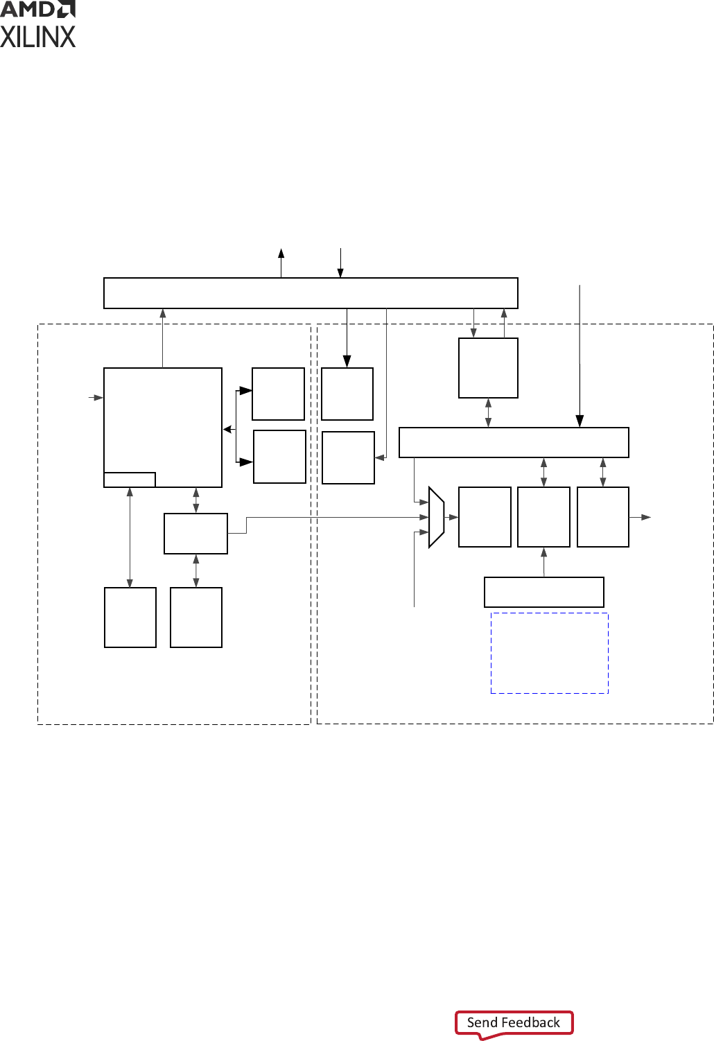
The CSU comprises two main blocks as shown in the following gure. On the le is the secure
processor block that contains a triple redundant processor for controlling boot operaon. It also
contains an associated ROM, a small private RAM, and the necessary control/status registers
required to support all secure operaons. The block on the right is the crypto interface block
(CIB) and contains the AES-GCM, DMA, SHA, RSA, and PCAP interfaces.
Figure 2: Configuration and Security Unit Architecture
CSU PMU Switch
ROM
Validation
ROM
(128 KB)
RAM
(32 KB)
Triple
Redundant
MicroBlaze
SHA-3
384
AES-
GCM
256
Secure Stream Switch
PCAP
CSU DMA
CSU
Registers
Key
Management
To PL
Configuration
PMU ROM
Validation
To/From LPD Main Switch
Tamper
Sources
INTC
ECC
BBRAM
eFUSE
PUF
Operation
KUP
Family
CSU
Local
Registers
PUF
RSA
Multiplier
PSTP
Security Processor Block
Crypto Interface Block
X15318-032817
Aer
boot, the CSU provides tamper response monitoring. These crypto interfaces are available
during runme. To understand how to use these features, seethe XilFPGA Library v5.3 in the OS
and Libraries Document Collecon (UG643). See the Security chapter of the Zynq UltraScale+
Device Technical Reference Manual (UG1085) for more informaon.
• Secure Processor Block: The triple-redundant processor architecture enhances the CSU
operaons during single event upset (SEU) condions.
• Crypto Interface Block (CIB): Consists of AES-GCM, DMA, SHA-3/384, RSA, and PCAP
interfaces.
Chapter 2: Programming View of Zynq UltraScale+ MPSoC Devices
UG1137 (v2022.2) November 2, 2022 www.xilinx.com
Zynq UltraScale+ MPSoC: Software Developers Guide 17

• AES-GCM: The AES-GCM core has a 32-bit word-based data interface, with 256-bits of key
support.
• Key Management: To use the AES, a key must be loaded into the AES block. The key is
selected by CSU bootROM.
• SHA-3/384: The SHA-3/384 engine is used to calculate a hash value of the input image for
authencaon.
• RSA-4096 Accelerator: Facilitates RSA authencaon.
To understand boot image encrypon or authencaon, refer to the following:
• Chapter 7: System Boot and Conguraon
• Chapter 16: Boot Image Creaon
• The Security chapter of the Zynq UltraScale+ Device Technical Reference Manual (UG1085).
• Boot and Conguraon informaon in the Zynq UltraScale+ Device Technical Reference Manual
(UG1085).
System-Level Protections
The system-level protecon mechanism involves the following areas:
• Zynq UltraScale+ MPSoC Linux soware stack relies on the Trusted Firmware-A (TF-A).
Protecon can be enhanced even further by conguring the XMPU and XPPU to provide the
system-level run-me security.
○ Protecon against buggy or malicious soware (erroneous soware) from corrupng
system memory or causing a system failure.
○ Protecon against incorrect programming, or malicious devices (erroneous hardware) from
corrupng system memory or causing a system failure.
○ Memory (DDR, OCM) and peripherals (peripheral control, SLCRs) are protected from illegal
accesses by erroneous soware or hardware to protect the system.
• The Xilinx memory protecon unit (XMPU) enforces memory paroning and TrustZone (TZ)
protecon for memory and FPD slaves. The XMPU can be congured to isolate a master or a
given set of masters to a developer-dened set of address ranges.
• The Xilinx peripheral protecon unit (XPPU) provides LPD peripheral isolaon and inter-
processor interrupt (IPI) protecon. The XPPU can be congured to permit one or more
masters to access an LPD peripheral. For more informaon, see the XPPU Protecon of Slaves
secon of the Zynq UltraScale+ Device Technical Reference Manual (UG1085).
Chapter 2: Programming View of Zynq UltraScale+ MPSoC Devices
UG1137 (v2022.2) November 2, 2022 www.xilinx.com
Zynq UltraScale+ MPSoC: Software Developers Guide 18

Safety and Reliability
The Zynq UltraScale+ MPSoC architecture includes features that enhance the reliability of safety
crical applicaons to give users and designers increased condence in their systems. The key
features are as follows:
• Memory and cache error detecon and correcon
• RPU safety features
• System-wide safety features
To understand how to use these features, see Chapter 8: Security Features.
Safety Features
The Cortex-A53 MPCore processor supports cache protecon in the form of ECC on all RAM
instances in the processor using the following separate protecon elements:
• SCU-L2 cache protecon
• CPU cache protecon
These elements enable the Cortex-A53 MPCore processor to detect and correct a 1-bit error in
any RAM, and to detect 2-bit errors.
Cortex-A53 MPCore RAMs are protected against single-event-upset (SEU) such that the
processor system can detect and then, take specic acon to connue making progress without
data corrupon. Some RAMs have parity single-error detect (SED) capability, while others have
ECC single-error correct, double-error detect (SECDED) capability.
The RPU includes two major safety features:
• Lock-step operaon, shown in the following gure.
• Error checking and correcon, described further in Error Checking and Correcon.
Lock-Step Operation
Cortex-R5F processors support lock-step operaon mode, which operates both RPU CPU cores
as a redundant CPU conguraon called safety mode.
The Cortex-R5F processor set to operate in the lock-step conguraon exposes only one CPU
interface. Because Cortex-R5F processor only supports the stac split and lock conguraon,
switching between these modes is permied only while the processor group is held in power-
onreset (POR). The input signals SLCLAMP and SLSPLIT control the mode of the processor
group.
Chapter 2: Programming View of Zynq UltraScale+ MPSoC Devices
UG1137 (v2022.2) November 2, 2022 www.xilinx.com
Zynq UltraScale+ MPSoC: Software Developers Guide 19

These signals control the mulplex and clamp logic in the lock-step conguraon. When the
Cortex-R5F processors are in the lock-step mode (shown in the following gure), there must be
code in the reset handler to manage that the distributor within the GIC dispatches interrupts only
to CPU0. The RPU includes a dedicated interrupt controller for Cortex-R5F MPCore processors.
This Arm PL390 generic interrupt controller (GIC) is based on the GICv1 specicaon.
Figure 3: RPU Lock-Step Operation
X14824-062717
TCMs Associated
with CPU1
TCM A
TCM B
TCMs Associated
with CPU0
TCM A
TCM B
Shim Shim
Cortex-R5F
CPU0
Cortex-
R5F CPU0
Comparison and Synchronization Logic
Caches Associated
with CPU0
D-Cache
I-Cache
GIC
Tightly coupled memories (TCMs) are mapped in the local address space of each Cortex-R5F
processor; however, they are also mapped in the global address space where any master can
access them provided that the XPPU is congured to allow such accesses.
The following table lists the address maps from the RPU point of view:
Table 2: RPU Address Maps
Operation Mode Memory
R5_0 View (Start
Address)
R5_1 View (Start
Address)
Global Address
View (Start
Address)
Split Mode R5_0 ATCM (64 KB) 0x0000_0000 N/A 0xFFE0_0000
R5_0 BTCM (64 KB) 0x0002_0000 N/A 0xFFE2_0000
R5_0 instruction cache I-Cache N/A 0xFFE4_0000
R5_0 data cache D-Cache N/A 0xFFE5_0000
Split Mode R5_1 ATCM (64 KB) N/A 0x0000_0000 0xFFE9_0000
R5_1 BTCM (64 KB) N/A 0x0002_0000 0xFFEB_0000
R5_1 instruction cache I-Cache N/A 0xFFEC_0000
R5_1 data cache D-Cache N/A 0xFFED_0000
Lock-step Mode R5_0 ATCM (128 KB) 0x0000_0000 N/A 0xFFE0_0000
R5_0 BTCM (128 KB) 0x0002_0000 N/A 0xFFE2_0000
R5_0 instruction cache I-Cache N/A 0xFFE4_0000
R5_0 data cache D-Cache N/A 0xFFE5_0000
Chapter 2: Programming View of Zynq UltraScale+ MPSoC Devices
UG1137 (v2022.2) November 2, 2022 www.xilinx.com
Zynq UltraScale+ MPSoC: Software Developers Guide 20

Error Checking and Correction
The Cortex-R5F processor supports error checking and correcon (ECC) schemes of data. The
data has similar properes although the size of the data chunk to which the ECC scheme applies
is dierent.
For each aligned data chunk, the processor computes and stores a number of redundant code
bits with the data. This enables the processor to detect up to two errors in the data chunk or its
code bits, and correct any single error in the data chunk or its associated code bits. This is also
referred to as a single-error correcon, double-error detecon (SEC-DED) ECC scheme.
System-Wide Safety Features
The system-wide safety features are designed to address error-free operaon of the
Zynq UltraScale+ MPSoC.
These features include the following:
Platform Management Unit
The plaorm management unit (PMU) in the Zynq UltraScale+ MPSoC executes the code loaded
from ROM and RAM within a at memory space, implements power safety rounes to prevent
tampering of PS voltage rails, performs logic built-in self-test (LBIST), and responds to a user-
driven power management sequence.
The PMU also includes some registers to control the funcons that are typically very crical to
the operaon and safety of the device. Some of the registers related to safety are as follows:
• GLOBAL_RESET: Contains reset for safety-related blocks.
• SAFETY_GATE: Gates hardware features from accidental enablement.
• SAFETY_CHK: Checks the integrity of the interconnect data lines by using target registers for
safety applicaons by periodically wring to and reading from these registers.
PMU Triple-Redundancy
The power management unit (PMU) contains triple-redundant MicroBlaze™ processors for a
high-level of system reliability and strong SEU resilience. PMU controls the power-up, reset, and
monitoring of resources within the enre system. The PMU performs mulple tasks including the
following tasks:
• Inializing the system during boot
• Managing power gang and retenon states for dierent power domains and islands
• Communicang the supply voltage sengs to the external power control devices
• Managing sleep states including the deep-sleep mode and processing of wake funcons
Chapter 2: Programming View of Zynq UltraScale+ MPSoC Devices
UG1137 (v2022.2) November 2, 2022 www.xilinx.com
Zynq UltraScale+ MPSoC: Software Developers Guide 21

More details about PMU are available in Chapter 9: Plaorm Management.
Interrupts
The generic interrupt controller (GIC) handles interrupts. Both the APU and the RPU have a
separate dedicated GIC for interrupt handling. The RPU includes an Arm PL390 GIC, which is
based upon the GICv1 specicaon due to its exibility and protecon. The APU includes a
GICv2 controller. The GICv2 is a centralized resource for supporng and managing interrupts in
mul-processor systems. It aids the GIC virtualizaon extensions that support the
implementaon of the GIC in systems supporng processor virtualizaon.
The Zynq UltraScale+ MPSoC embeds an inter-processor interrupt (IPI) block that aids in
communicaon between the heterogeneous processors. Because PMUs can communicate with
dierent processors simultaneously, the PMU has four IPIs connected to the GIC of the PMU.
For more informaon on IPI roung to dierent processors, see the “Interrupts” chapter in the
Zynq UltraScale+ Device Technical Reference Manual (UG1085).
Memory Overview for APU and RPU
Executables
The following tables give the congurable memory regions for APUs and RPUs.
Note:
•
In RPU lock-step mode (Lock-Step Operaon), R5_0_ATCM_MEM_0 and R5_0_BTCM_MEM_0 memory
address are mapped to R5_0_ATCM_LSTEP and R5_0_BTCM_LSTEP memory ranges respecvely in the
system address map.
•
In RPU split mode, R5_x_ATCM_MEM_0 and R5_x_BTCM_MEM_0 memory address are mapped to
R5_x_ATCM_SPLIT and R5_x_BTCM_SPLIT memory ranges respecvely in the system address map.
•
QSPI memory is accessible when QSPI controller is in linear mode.
See the System Addresses chapter of the Zynq UltraScale+ Device Technical Reference Manual
(UG1085) for more informaon.
See Real-me Processing Unit (RPU) and On-Chip Memory (OCM) secons of the Zynq UltraScale
+ Device Technical Reference Manual (UG1085) for more informaon on RPU, R5 and OCM.
Table 3:
Configurable Memory Regions for APUs
Memory Type Start Address Size
DDR Low 0x00000000 2 GB
DDR High 0x800000000 2 GB
Chapter 2: Programming View of Zynq UltraScale+ MPSoC Devices
UG1137 (v2022.2) November 2, 2022 www.xilinx.com
Zynq UltraScale+ MPSoC: Software Developers Guide 22

Table 3: Configurable Memory Regions for APUs (cont'd)
Memory Type Start Address Size
OCM 0xFFFC0000 256 KB
QSPI 0xC0000000 512 MB
Table 4: Configurable Memory Regions for RPU Lock-Step Mode
Memory Type Start Address Size
DDR Low 0x100000 2047 MB
OCM 0xFFFC0000 256 KB
QSPI 0xC0000000 512 MB
R5_0_ATCM_MEM_0 0x00000 64 KB
R5_0_BTCM_MEM_0 0x20000 64 KB
R5_TCM_RAM_0_MEM 0x00000 256 KB
Table 5: Configurable Memory Regions for RPU Split Mode
Memory Type Start Address Size
R5_0
DDR Low 0x100000 2047 MB
OCM 0xFFFC0000 256 KB
QSPI 0xC0000000 512 MB
R5_0_ATCM_MEM_0 0x00000 64 KB
R5_0_BTCM_MEM_0 0x20000 64 KB
R5_1
DDR Low 0x100000 2047 MB
OCM 0xFFFC0000 256 KB
QSPI 0xC0000000 512 MB
R5_1_ATCM_MEM_0 0x00000 64 KB
R5_1_BTCM_MEM_0 0x20000 64 KB
Note: BootROM always copies First Stage Boot Loader (FSBL) from 0xFFFC0000 and it is not congurable.
If FSBL is compiled for a dierent load address, Bootgen may refuse it as CSU bootROM (CBR) does not
parse paron headers in the boot image but merely copies the FSBL code at a xed OCM memory
locaon (0xfffc0000). See Chapter 7: System Boot and Conguraon for more informaon on Bootgen.
Chapter 2: Programming View of Zynq UltraScale+ MPSoC Devices
UG1137 (v2022.2) November 2, 2022 www.xilinx.com
Zynq UltraScale+ MPSoC: Software Developers Guide 23

Chapter 3
Development Tools
This chapter focuses on Xilinx
®
tools and ows available for programming soware for
Zynq
®
UltraScale+™ MPSoCs. However, the concepts are generally applicable to third-party tools
as the Xilinx tools incorporate familiar components such as an
Eclipse-based integrated development environment (IDE) and the GNU compiler tool chain.
This chapter also provides a brief descripon about the open source tools available that you can
use for open source development on dierent processors of the Zynq UltraScale+ MPSoC.
A comprehensive set of tools for developing and debugging soware applicaons on
Zynq UltraScale+ MPSoC devices includes:
• Hardware IDE
• Soware IDEs
• Compiler toolchain
• Debug and trace tools
• Embedded OS and soware libraries
• Simulators (for example: QEMU)
• Models and virtual prototyping tools (for example: emulaon board plaorms)
Third-party tool soluons vary in the level of integraon and direct support for
Zynq UltraScale+ MPSoC devices.
The following secons provide a summary of the available Xilinx development tools.
Vivado Design Suite
The Xilinx Vivado
®
Design Suite contains tools that are encapsulated in the Vivado integrated
design environment (IDE). The IDE provides an intuive graphical user interface (GUI) with
powerful features.
Chapter 3: Development Tools
UG1137 (v2022.2) November 2, 2022 www.xilinx.com
Zynq UltraScale+ MPSoC: Software Developers Guide 24

The Vivado Design Suite supersedes the Xilinx ISE soware with addional features for system-
on-a-chip development and high-level synthesis. It delivers a SoC-strength, IP- and system-
centric, next generaon development environment built exclusively by Xilinx to address the
producvity bolenecks in system-level integraon and implementaon.
All of the tools and tool opons in Vivado Design Suite are wrien in nave Tool Command
Language (Tcl) format, which enables use both in the Vivado IDE or the Vivado Design Suite Tcl
shell. Analysis and constraint assignment is enabled throughout the enre design process. For
example, you can run ming or power esmaons aer synthesis, placement, or roung. Because
the database is accessible through Tcl, changes to constraints, design conguraon, or tool
sengs happen in real me, oen without forcing re-implementaon.
The Vivado IDE uses a concept of opening designs in memory. Opening a design loads the design
netlist at that parcular stage of the design ow, assigns the constraints to the design, and then
applies the design to the target device. This provides the ability to visualize and interact with the
design at each design stage.
IMPORTANT! The Vivado IDE supports designs that target 7 series and newer devices only.
You can improve design performance and ease of use through the features delivered by the
Vivado Design Suite, including:
• The Processor Conguraon Wizard (PCW) within the IP integrator with graphical user
interfaces to let you create and modify the PS within the IP integrator block design.
VIDEO: For a beer understanding of the PCW, see the Quick Take Video: Vivado Processor
Conguraon Wizard Overview.
• Register transfer level (RTL) design in VHDL, Verilog, and SystemVerilog.
• Quick integraon and conguraon of IP cores from the Xilinx IP catalog to create block
designs through the Vivado IP integrator.
• Vivado synthesis.
• C-based sources in C, C++, and SystemC.
• Vivado implementaon for place and route.
• Vivado serial I/O and logic analyzer for debugging.
• Vivado power analysis.
• SDC-based Xilinx Design Constraints (XDC) for ming constraints entry.
• Stac ming analysis.
• Flexible oorplanning.
• Detailed placement and roung modicaon.
• Bitstream generaon.
Chapter 3: Development Tools
UG1137 (v2022.2) November 2, 2022 www.xilinx.com
Zynq UltraScale+ MPSoC: Software Developers Guide 25

• Vivado Tcl Store, which you can use to add to and modify the capabilies in Vivado.
You can download the Vivado Design Suite from the Xilinx Vivado Design Suite – ML Edions.
Vitis Unified Software Platform
The Vis™ unied soware plaorm is an integrated development environment (IDE) for the
development of embedded soware applicaons targeted towards Xilinx embedded processors.
The Vis soware plaorm works with hardware designs created with Vivado Design Suite. The
Vis soware plaorm is based on the Eclipse open source standard and the features for
soware developers include:
• Feature-rich C/C++ code editor and compilaon environment
• Project management
• Applicaon build conguraon and automac Makele generaon
• Error navigaon
• Integrated environment for seamless debugging and proling of embedded targets
• Source code version control
• System-level performance analysis
• Focused special tools to congure FPGA
• Bootable image creaon
• Flash programming
• Script-based command-line tool
The Vis IDE lets you create soware applicaons using a unied set of Xilinx tools for the Arm
®
Cortex
®
-A53 and Cortex
®
-R5F processors as well as for Xilinx MicroBlaze™ processors. It
provides various methods to create applicaons, as follows:
• Bare metal and FreeRTOS applicaons for MicroBlaze
• Bare metal, Linux, and FreeRTOS applicaons for APU
• Bare metal and FreeRTOS applicaons for RPU
• User customizaon of PMU rmware
• Library examples are provided with the Vis tool (ready to load sources and build), as follows:
○ OpenCV
○ OpenAMP RPC
○ FreeRTOS “HelloWorld”
Chapter 3: Development Tools
UG1137 (v2022.2) November 2, 2022 www.xilinx.com
Zynq UltraScale+ MPSoC: Software Developers Guide 26

○ lwIP
○ Performance tests (Dhrystone, memory tests, peripheral tests)
○ RSA authencaon for prevenng tampering or modicaon of images and bitstream
○ First stage boot loader (FSBL) for APU or RPU.
You can export a block design, hardware design les, and bitstream les to the export directory
directly from the Vivado Project Navigator. For more informaon regarding the Vivado Design
Suite, see the Vivado Design Suite Documentaon.
All processes necessary to successfully complete this export process are run automacally. The
Vis IDE creates a new hardware plaorm project within the workspace containing the following
les:
• .project: Project le
• psu_init.tcl: PS inializaon script
• psu_init.c, psu_init.h: PS inializaon code
• psu_init.html: Register summary viewer
• system.hdf: Hardware denion le
The compiler can be switched as follows:
• 32-bit or 64-bit (applicaons that are targeted to Cortex-A53)
• 32-bit only (applicaons targeted to Cortex-R5F, and Xilinx MicroBlaze devices)
For the list of build procedures, see the Vis Unied Soware Plaorm Documentaon: Embedded
Soware Development (UG1400), where built-in help content lets you explore further aer you
launch the Vis IDE.
The Vis soware plaorm has the following IDE extensions.
• XSCT Console: Xilinx Soware Command-line Tool (XSCT) is an interacve and scriptable
command-line interface to the Vis soware plaorm. As with other Xilinx tools, the scripng
language for XSCT is based on Tools Command Language (Tcl). You can run XSCT commands
interacvely or script the commands for automaon. XSCT supports the following acons.
• Creang plaorm projects and applicaon projects
• Manage repositories
• Manage domain sengs and add libraries to domains
• Set toolchain preferences
• Congure and build applicaons
• Download and run applicaons on hardware targets
Chapter 3: Development Tools
UG1137 (v2022.2) November 2, 2022 www.xilinx.com
Zynq UltraScale+ MPSoC: Software Developers Guide 27

• Create and ash boot images by running Bootgen and program_ash tools
• Bootgen Ulity: Bootgen is a Xilinx tool that lets you stch binary les together and generate
device boot images. Bootgen denes mulple properes, aributes and parameters that are
input while creang boot images for use in a Xilinx device. Bootgen comes with both a
graphical user interface and a command line opon. The tool is integrated into the Vis
soware plaorm for generang basic boot images using a GUI, but the majority of Bootgen
opons are command line-driven. For more informaon on the Bootgen ulity, see the
Bootgen User Guide (UG1283).
• Program Flash: Program Flash is a tool used to program the ash memories in the design.
Various types of ash types are supported by the Vis soware plaorm for programming.
• Repositories: A soware repository is a directory where you can install third-party soware
components, as well as custom copies of drivers, libraries, and operang systems. When you
add a soware repository, the Vis soware plaorm automacally infers all the components
contained with the repository and makes them available for use in its environment. Your
workspace can point to mulple soware repositories.
• Program FPGA: You can use the Program FPGA feature to program FPGA using bitstream.
• Device Tree Generaon: Device tree (DT) is a data structure that describes hardware. This
describes hardware that is readable by an operang system like Linux so that it does not need
to hard code details of the machine. Linux uses the DT basically for plaorm idencaon,
runme conguraon like bootargs, and device node populaon.
For a detailed explanaon on the Vis IDE features, and to understand the embedded soware
design ow, see the Vis Unied Soware Plaorm Documentaon: Embedded Soware
Development (UG1400).
You can download the Vis tool from the Embedded Design Tools Download.
Arm GNU Tools
The Arm GNU open source toolchain is adopted for the Xilinx soware development plaorm.
The GNU tools for Linux hosts are available as part of Vis soware plaorm. This secon details
the open source GNU tools and Linux tools available for the processing clusters in the
Zynq UltraScale+ MPSoC.
The following table lists some of the Xilinx Arm GNU tools available for programming the APU,
RPU, and embedded MicroBlaze processors.
Chapter 3: Development Tools
UG1137 (v2022.2) November 2, 2022 www.xilinx.com
Zynq UltraScale+ MPSoC: Software Developers Guide 28

Table 6: Xilinx Arm GNU Tools
Tool Description
aarch64-none-elf-gcc
aarch64-none-elf-g++
GNU C/C++ compiler.
aarch64-none-elf-as GNU assembler.
aarch64-none-elf-ld GNU linker.
aarch64-none-elf-ar A utility for creating, modifying, and extracting from
archives.
aarch64-none-elf-objcopy Copies and translates object files.
aarch64-none-elf-objdump Displays information from object files.
aarch64-none-elf-size Lists the section sizes of an object or archive file.
aarch64-none-elf-gprof Displays profiling information.
aarch64-none-elf-gdb The GNU debugger.
Device Tree Generator
The device tree (DT) data structure consists of nodes with properes that describe a hardware.
The Linux kernel uses the device tree to support a wide range of hardware conguraons.
In FPGAs, it is possible to have dierent combinaons of peripheral logics, each using a dierent
conguraon. For all the dierent combinaons, the device tree generator (DTG) generates
the .dts/.dtsi device tree les.
The following is a list of the .dts/.dtsi les generated by the device tree generator:
• pl.dtsi: Contains all the memory mapped peripheral logic (PL) IPs.
• pcw.dtsi: Contains the dynamic properes for the PS IPs.
• system-top.dts: Contains the memory, boot arguments, and command line parameters.
• zynqmp.dtsi: Contains all the PS specic and the CPU informaon.
• zynqmp-clk-ccf.dtsi: Contains all the clock informaon for the PS peripheral IPs.
For more informaon, see the Build Device Tree Blob page on the Xilinx Wiki.
PetaLinux Tools
The PetaLinux tools oer everything necessary to customize, build, and deploy open source
Linux soware to devices.
Chapter 3: Development Tools
UG1137 (v2022.2) November 2, 2022 www.xilinx.com
Zynq UltraScale+ MPSoC: Software Developers Guide 29

PetaLinux tools include the following:
• Build tools such as GNU, petalinux-build, and make to build the kernel images and the
applicaon soware.
• Debug tools such as GDB, petalinux-boot, and oprofile for proling.
The following table shows the supported PetaLinux tools.
Table 7: PetaLinux Supported Tools
Tools Description
GNU Arm GNU tools.
petalinux-build Used to build software image files.
Make Make build for compiling the applications.
GDB GDB tools for debugging.
petalinux-boot Used to boot Linux.
QEMU Emulator platform for the Zynq UltraScale+ MPSoC device.
OProfile Used for profiling.
See the following documentaon for more details:
• PetaLinux Tools documentaon
• Zynq UltraScale+ MPSoC: Embedded Design Tutorial (UG1209)
• Libmetal and OpenAMP for Zynq Devices User Guide (UG1186)
Linux Software Development using Yocto
Xilinx oers the meta-xilinx Yocto/OpenEmbedded recipes to enable those customers with
in-house Yocto build systems to congure, build, and deploy Linux for Zynq
®
UltraScale+™
MPSoCs.
The meta-xilinx layer also provides a number of BSPs for common boards which use Xilinx
devices.
The meta-xilinx layer provides addional support for Yocto/OE, adding recipes for various
components. See meta-xilinx for more informaon.
You can develop Linux soware on Cortex-A53 using open source Linux tools. This secon
explains the Linux Yocto tools and its project development environment.
The following table lists the Yocto tools.
Chapter 3: Development Tools
UG1137 (v2022.2) November 2, 2022 www.xilinx.com
Zynq UltraScale+ MPSoC: Software Developers Guide 30

Table 8: Yocto Tools
Tool Type Name Description
Yocto build tools Bitbake Generic task execution engine that
allows shell and Python tasks to be run
efficiently, and in parallel, while
working within complex inter-task
dependency constraints.
Yocto profile and trace tools
Perf Profiling and tracing tool that comes
bundled with the Linux Kernel.
Ftrace Refers to the ftrace function tracer but
encompasses a number of related
tracers along with the infrastructure
used by all the related tracers.
Oprofile System-wide profiler that runs on the
target system as a command-line
application.
Sysprof System-wide profiler that consists of a
single window with three panes, and
buttons, which allow you to start, stop,
and view the profile from one place.
Blktrace A tool for tracing and reporting low-
level disk I/O.
Yocto Project Development Environment
Developers can congure the Yocto project development environment to support developing
Linux soware for Zynq UltraScale+ MPSoCs through Yocto recipes provided from the Xilinx GIT
server. You can use components from the Yocto project to design, develop, and build a Linux-
based soware stack.
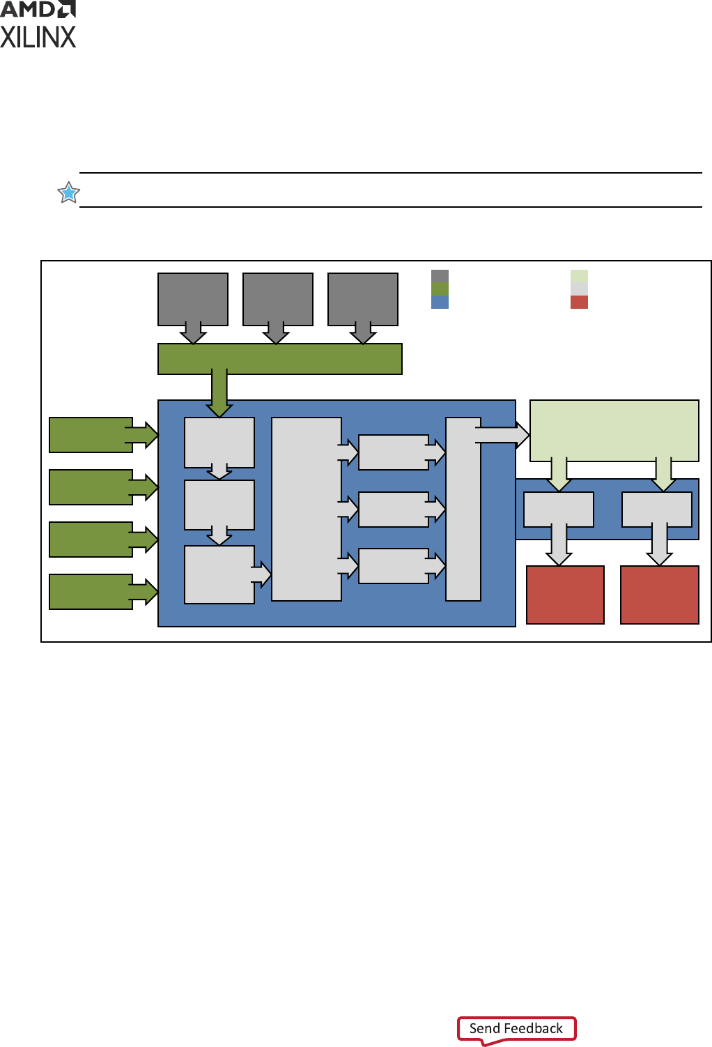
The following gure shows the complete Yocto project development environment. The Yocto
project has wide range of tools which can be congured to download the latest Xilinx kernel and
build with some enhancements made locally in the form of local projects.
You can also change the build and hardware conguraon through BSP.
Yocto combines a compiler and other tools to build and test images. Aer the images pass the
quality tests and package feeds required for SDK generaon are received, the Yocto tool
launches the Vis IDE for applicaon development.
The important features of the Yocto project are, as follows:
• Provides a recent Linux kernel along with a set of system commands and libraries suitable for
the embedded environment.
• Makes available system components such as X11, GTK+, Qt, Cluer, and SDL (among others)
so you can create a rich user experience on devices that have display hardware. For devices
that do not have a display or where you wish to use alternave UI frameworks, these
components need not be installed.
Chapter 3: Development Tools
UG1137 (v2022.2) November 2, 2022 www.xilinx.com
Zynq UltraScale+ MPSoC: Software Developers Guide 31
• Creates a focused and stable core compable with the OpenEmbedded project with which
you can easily and reliably build and develop Linux soware.
• Supports a wide range of hardware and device emulaon through the quick emulator (QEMU).
See the Xilinx Quick Emulator User Guide: QEMU for more informaon.
IMPORTANT! Enabling full Yocto of Xilinx QEMU is not available.
Figure 4: Yocto Project Development Environment
User Configuration
Metadata
(.bb+patches)
Machine(BSP)
Configuration
Policy Configuration
Source
Fetching
Patch
Application
Configuration /
Compile /
Autoreconf as
needed
Output
Analysis for
package
splitting plus
Package
relationships
.rpm
Generation
.deb
Generation
.ipk
Generation
QA
Tests
image
Generation
Images
Application
Development
SDK
Package Feeds
Source Mirror(s)
Upstream
Project
Releases
Local
Projects
SCMs
(optional)
Upstram Source
Metadata/Inputs
Build System
Output Packages
Process steps (Tasks)
Output Image Data
SDK
Generation
X14841-021317
You can download the Yocto tools and the Yocto project development environment from the
Yocto Project Organizaon.
For more informaon about Xilinx-provided Yocto features, see Yocto Features in the PetaLinux
Tools Documentaon: Reference Guide (UG1144).
Chapter 3: Development Tools
UG1137 (v2022.2) November 2, 2022 www.xilinx.com
Zynq UltraScale+ MPSoC: Software Developers Guide 32

Chapter 4
Software Stack
This chapter provides an overview of the various soware stacks available for the Zynq
®
UltraScale+™ MPSoC devices.
For more informaon about the various soware development tools used with this device, see
Chapter 3: Development Tools. For more informaon about bare metal and Linux soware
applicaon development, see Chapter 5: Soware Development Flow.
Bare Metal Software Stack
Xilinx
®
provides a bare metal soware stack called the standalone board support package (BSP)
as part of the Vis™ soware plaorm. The Standalone BSP gives you a simple, single-threaded
environment that provides basic features such as standard input/output and access to processor
hardware features. The BSP and included libraries are congurable to provide the necessary
funconality with the least overhead. You can locate the standalone drivers at the following path:
<Xilinx Installation Directory>\Vitis\<version>\data\embeddedsw
\XilinxProcessorIPLib\drivers
You can locate libraries at the following path:
<Xilinx Installation Directory>\Vitis\<version>\data\embeddedsw\lib
\sw_services
The following gure illustrates the bare metal soware stack in the APU.
Chapter 4: Software Stack
UG1137 (v2022.2) November 2, 2022 www.xilinx.com
Zynq UltraScale+ MPSoC: Software Developers Guide 33

Figure 5: Bare-Metal Software Development Stack
User Applications
Zynq UltraScale+ MPSoC Hardware
lwIP 211
XilFlash
XilSecure
XilFFS
Xilpm
XilSkey
Display
Driver
ZDMA
drivers
Ethernet
Driver
USB
Driver
SD card
Driver
Flash
Drivers
SPI, I2C,
UART
Drivers
SYSMON
Drivers
Libraries
Standalone
Drivers
XilFPGA
X17169-062121
Note: The soware stack of libraries and drivers layer for bare metal in RPU is same as that of APU.
The key components of this bare metal stack are:
• Soware drivers for peripherals including core rounes needed for using the Arm
®
Cortex
®
-
A53, Arm
®
Cortex
®
-R5F processors in the PS as well as the Xilinx
®
MicroBlaze™ processors in
the PL.
• Bare metal drivers for PS peripherals and oponal PL peripherals.
• Standard C libraries: libc and libm, based upon the open source Newlib library, ported to the
Arm Cortex-A53, Arm Cortex-R5F, and the MicroBlaze processors.
• Addional middleware libraries that provide networking, le system, and encrypon support.
• Applicaon examples including the rst stage boot loader (FSBL) and test applicaons.
The C Standard Library (libc)
libc library contains standard funcons that all C programs can use. The following table lists the
libc modules:
Table 9: Libc.a Functions and Descriptions
Header File Description
alloca.h Allocates space in the stack
assert.h Diagnostics code
ctype.h Character operations
errno.h System errors
inttypes.h Integer type conversions
Chapter 4: Software Stack
UG1137 (v2022.2) November 2, 2022 www.xilinx.com
Zynq UltraScale+ MPSoC: Software Developers Guide 34

Table 9: Libc.a Functions and Descriptions (cont'd)
Header File Description
math.h Mathematics
setjmp.h Non-local goto code
stdint.h Standard integer types
stdio.h Standard I/O facilities
stdlib.h General utilities functions
time.h Time function
The C Standard Library Mathematical Functions
(libm)
The following table lists the libm mathemacal C modules:
Table 10: libm.a Function Types and Function Listing
Function Type Supported Functions
Algebraic cbrt, hypot, sqrt
Elementary transcendental asin, acos, atan, atan2, asinh, acosh, atanh, exp, expm1, pow, log,
log1p, log10, sin, cos, tan, sinh, cosh, tanh
Higher transcendentals j0, j1, jn, y0, y1, yn, erf, erfc, gamma, lgamma, and gamma_ramma_r
Integral rounding eil, floor, rint
IEEE standard recommended copysign, fmod, ilogb, nextafter, remainder, scalbn, and fabs
IEEE classification isnan
Floating point logb, scalb, significand
User-defined error handling routine matherr
Standalone BSP
The libraries available with the standalone BSP are as follows:
• XilFatFS: A LibXil FATFile system and provides read/write access to les stored on a Xilinx
system ACE compact ash.
• XilFFS: Generic Fat File System Library.
• XilFlash: Xilinx ash library for Intel/AMD CFI compliant parallel ash.
• XilSecure: Xilinx Secure library provides an interface to access secure hardware (AES, RSA and
SHA) engines.
• XilSkey: Xilinx secure key library.
Chapter 4: Software Stack
UG1137 (v2022.2) November 2, 2022 www.xilinx.com
Zynq UltraScale+ MPSoC: Software Developers Guide 35

• XilFPGA: A library that provides an interface to the Linux or bare-metal users for conguring
the programmable logic (PL) over PCAP from PS.
• XilPM: Xilinx Power Management (XilPM) provides Embedded Energy Management Interface
(EEMI) APIs for power management on Zynq UltraScale+ MPSoC.
• XilMailbox: The XilMailbox library provides the top-level hooks for sending or receiving an
inter-processor interrupt (IPI) message using the Zynq UltraScale+ MPSoC IPI hardware
• lwIP Library: An open source TCP/IP protocol suite that provides access to the core lwIP stack
and BSD (Berkeley Soware Distribuon) sockets style interface to the stack.
These libraries are documented in The C Standard Library (libc).
.
Linux Software Stack
The Linux OS supports the Zynq UltraScale+ MPSoC. With the sole excepon of the Arm GPU,
Xilinx provides open source drivers for all peripherals in the PS as well as key peripherals in the
PL. The following gure illustrates the full soware stack in APU, including Linux and an oponal
hypervisor.
Chapter 4: Software Stack
UG1137 (v2022.2) November 2, 2022 www.xilinx.com
Zynq UltraScale+ MPSoC: Software Developers Guide 36

Figure 6: Linux Software Development Stack
Trusted
App1
Third Party Secure OS
ARM Trusted Firmware
EL0
EL1
EL2
EL3
Secure World
App1
App2 App3
Linux SMP
U-Boot/Hypervisor
Non-secure World
PMU Firmware
X18968-062121
The Armv8 excepon model denes excepon levels EL0–EL3, where:
• EL0 has the lowest soware execuon privilege. Execuon at EL0 is called unprivileged
execuon.
• Increased excepon levels, from 1 to 3, indicate an increased soware execuon privilege.
• EL1 runs the non-secure operang system in the non-secure world or a secure operang
system in the secure world when using a TEE architecture.
• EL2 provides support for processor virtualizaon. You may oponally include an open source
or commercial hypervisor in the soware stack.
• EL3 provides support for secure monitor soware. The Cortex-A53 MPCore processor
implements all the excepon levels (EL0-EL3) and supports both execuon states (AArch64
and AArch32) at each excepon level.
You can leverage the Linux soware stack for the Zynq UltraScale+ MPSoC in mulple ways. The
following are some of your opons:
• PetaLinux Tools: The PetaLinux tools include a branch of the Linux source tree, U-Boot as well
as Yocto-based tools to make it easy to build complete Linux images including the kernel, the
root le system, device tree, and applicaons for Xilinx devices. See the PetaLinux Product
Page for more informaon. The PetaLinux tools work with the same open source Linux
components described immediately below.
Chapter 4: Software Stack
UG1137 (v2022.2) November 2, 2022 www.xilinx.com
Zynq UltraScale+ MPSoC: Software Developers Guide 37

• Open Source Linux and U-Boot: The Linux Kernel sources including drivers, board
conguraons, and U-Boot updates for the Zynq UltraScale+ MPSoC are available from the
Xilinx GitHub link, and on a connuing basis from the main Linux kernel and U-Boot trees as
well. Yocto board support packages are also available from the main Yocto tree.
• Commercial Linux Distribuons: Some commercial distribuons also include support for Xilinx
UltraScale+ MPSoC devices and they include advanced tools for Linux conguraon,
opmizaon, and debug. You can nd more informaon about these from the Xilinx
Embedded Compung page.
Multimedia Stack Overview
This secon describes the mulmedia soware stack in the Zynq UltraScale+ MPSoC.
The GPU and a high performance DisplayPort accelerate the graphics applicaon. The GPU
provides hardware acceleraon for 2D and 3D graphics by including one geometry processor
(GP) and two pixel processors (PP0 and PP1), each having a dedicated memory management unit
(MMU). The cache coherency between the APU and the GPU is achieved by cache-coherent
interconnect (CCI), which supports the AXI coherency extension (ACE) only.
CCI in-turn connects the APU and the GPU to the DDR controller, which arbitrates the DDR
access.
The following gure shows the mulmedia stack.
Chapter 4: Software Stack
UG1137 (v2022.2) November 2, 2022 www.xilinx.com
Zynq UltraScale+ MPSoC: Software Developers Guide 38

Figure 7: Multimedia Stack
Graphics Application
Display Server
Ex: XII, Wayland
Mali common
Libraries
Video Codecs
Graphic Libraries
Ex: Open GLES1,
Open GLES 2, Open
VG
Gstreamer
Frame Buffer
Driver
Display Drivers
Video Drivers
Ex: V4L2
Mali Graphic
Drivers
DRM
APU
Linux Kernel Drivers
DDR Controller
Memory
GPO PPO PP1
Display Port
ARM MALI GPU
Cache Coherent
Interconnect
Ffmpeg pipeline
X14795-110320
The Linux kernel drivers for mulmedia enables the hardware access by the applicaons running
on the processors.
The following table lists the mulmedia drivers through the middleware stack that consists of the
libraries and framework components the applicaons use.
Table 11:
Libraries and Framework Components
Component Description
Display server Coordinates the input and output from the applications to
the operating system.
Chapter 4: Software Stack
UG1137 (v2022.2) November 2, 2022 www.xilinx.com
Zynq UltraScale+ MPSoC: Software Developers Guide 39

Table 11: Libraries and Framework Components (cont'd)
Component Description
Graphics library The Zynq UltraScale+ MPSoC architecture supports OpenGL
ES 1.1 and 2.2, and Open VG 1.1.
Mali™-400 MP2 common libraries Mali-400 MP2 graphic libraries. For more details on how to
switch between different EGL backends, refer to Xilinx MALI
Driver.
Gstreamer A freeware multimedia framework that allows a
programmer to create a variety of media handling
components.
Video codecs Video encoders and decoders.
The following table lists the Linux kernel graphics drivers.
Table 12: Linux Kernel Drivers
Drivers Description
Frame buffer driver Kernel graphics driver exposing its interface through /dev/
fb*. This interface implements limited functionality
(allowing you to set a video mode and drawing to a linear
frame buffer).
Direct rendering manager (DRM) Serves in rendering the hardware between multiple user
space components.
Mali-400 MP2 graphics drivers Provides the hardware access to the GPU hardware.
Video drivers Video capture and output device pipeline drivers based on
the V4L2 framework. The Xilinx Linux V4L2 pipeline driver
represents the whole pipeline with multiple sub-devices.
You can configure the pipeline through the media node, and
you can perform control operations, such as stream on/off,
through the video node.
Device nodes are created be the pipeline driver. The
pipeline driver also includes the wrapper layer of the DMA
engine API, and this enables it to read/write frames from
RAM.
Display port drivers
Enables the hardware access to the display port, based on
DRM framework.
FreeRTOS Software Stack
Xilinx provides a FreeRTOS board support package (BSP) as a part of the Vis™ soware
plaorm. The FreeRTOS BSP provides you a simple, mul-threading environment with basic
features such as, standard input/output and access to processor hardware features. The BSP and
the included libraries are highly congurable to provide you the necessary funconality with the
least overhead. The FreeRTOS soware stack is similar to the bare metal soware stack, except
that it contains the FreeRTOS library. Xilinx device drivers included with the standalone libraries
Chapter 4: Software Stack
UG1137 (v2022.2) November 2, 2022 www.xilinx.com
Zynq UltraScale+ MPSoC: Software Developers Guide 40
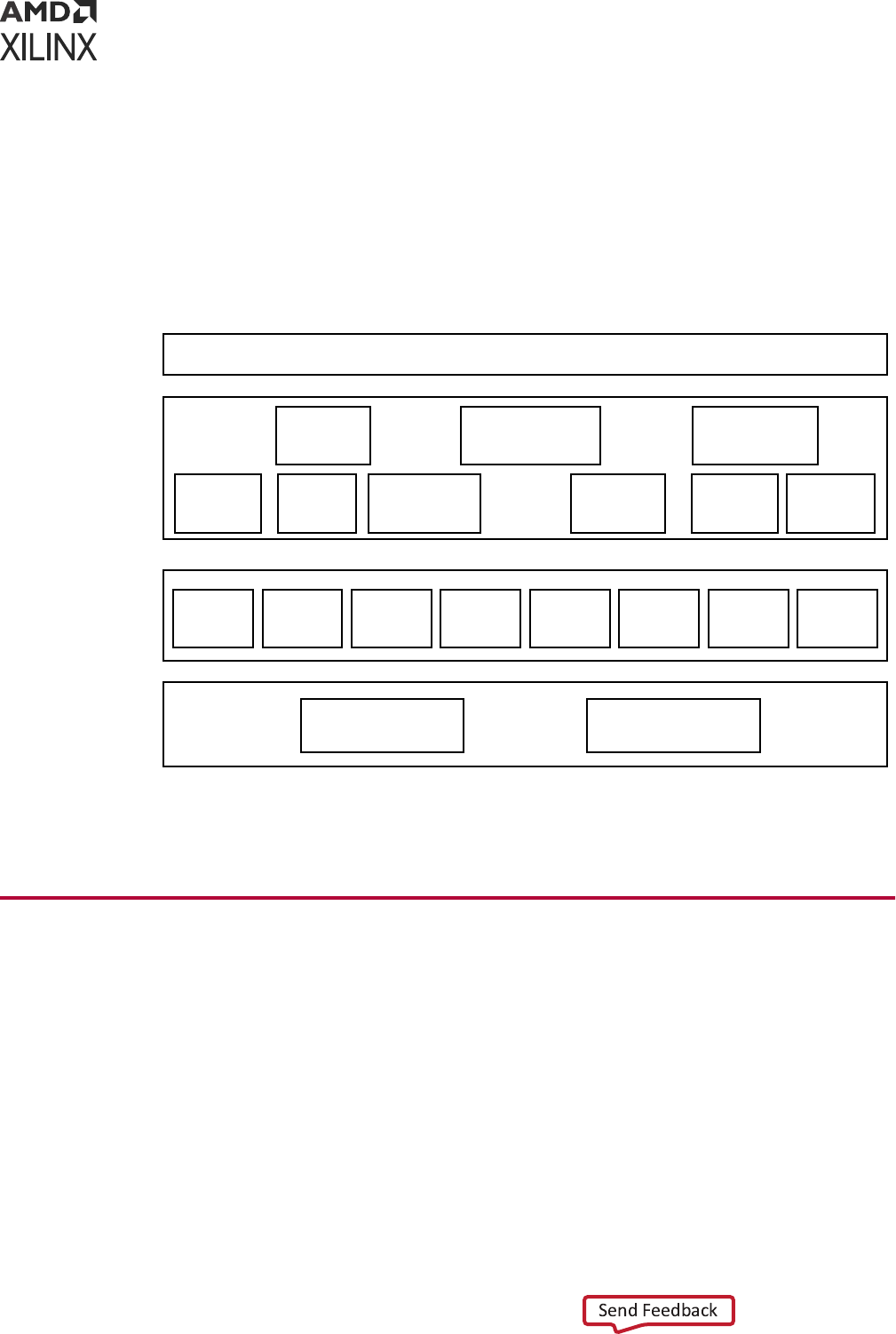
can typically be used within FreeRTOS provided that only a single thread requires access to the
device. Xilinx bare metal drivers are not aware of Operang Systems. They do not provide any
support for mutexes to protect crical secons, nor do they provide any mechanism for
semaphores to be used for synchronizaon. While using the driver API with FreeRTOS kernel,
you must take care of this aspect.
The following gure illustrates the FreeRTOS soware stack for RPU.
Figure 8: FreeRTOS Software Stack
X16911-062121
User Applications
Lwip Networking File system (xilffs)
Secure Key
(xilkey)
Standard ‘C’
Library(libxil.a)
Display
Driver
ZDMA
drivers
Ethernet
Driver
USB
Driver
SD card
Driver
Flash
Drivers
SPI, I2C,
UART
Drivers
SYSMON
Drivers
Libraries
Drivers
Secure
(xilsecure)
Power Mgr API
(xilpm)
OpenAmp
(xilopenamp)
Parallel Flash
(xilflash)
ARM Cortex-R5 Core 0
RPU
FreeRTOS
ARM Cortex-R5 Core 1
Note: The FreeRTOS soware stack for APU is same as that for RPU except that the libraries support both
32-bit and 64-bit for APU.
Third-Party Software Stack
Many other embedded soware soluons are also available from the Xilinx partner ecosystem.
More informaon is available from the Xilinx website, Embedded Compung and the website,
Xilinx Third Party Tools.
Chapter 4: Software Stack
UG1137 (v2022.2) November 2, 2022 www.xilinx.com
Zynq UltraScale+ MPSoC: Software Developers Guide 41

Chapter 5
Software Development Flow
This chapter explains the bare metal soware development for RPU and APU using the Vis™
unied soware plaorm as well as Linux soware development for APU using PetaLinux tools
and the Vis soware plaorm.
The following gure depicts the top-level soware architecture of the
Zynq
®
UltraScale+™ MPSoC.
Chapter 5: Software Development Flow
UG1137 (v2022.2) November 2, 2022 www.xilinx.com
Zynq UltraScale+ MPSoC: Software Developers Guide 42

Figure 9: Software Development Architecture
Software Development
Tools
IDE
Boot Loader
Ex: U-Boot
Power Management
Firmware
Hardware
Handoff
Build Tools
Compiler Assembler
Linker
Zynq UltraScale+ MPSoC Hardware
Quad core
ARM-A53 APU
ARM Mali400
GPU
Dual core ARM
Cortex-R5F RPU
Enhanced DSP
and AXI
Platform
Management
Unit
System
Configuration
and Security Unit
DDR Memory
Controller
Debugger Profiler
Simulator Flash Writer
Debug Tools
· Configure PS
· Integrate IP
· Export Hardware to SDK
Vivado
Software
Hardware
OS Kernel
Applications
Middleware Stack
(Ex: Graphics, File system)
System Software
(Ex: Hypervisor, OpenAMP)
Security Management
Software
Software Stack
Programmable
Logic
Peripherals
OS Kernel
Drivers
X14793-051519
Bare Metal Application Development
This secon assists you in understanding the design ow of bare metal applicaon development
for APU and RPU using the Vis soware plaorm. The following gure shows the top-level
design ow in the Vis soware plaorm. You can create a C or C++ standalone applicaon
project by using the New Applicaon Project wizard.
Chapter 5: Software Development Flow
UG1137 (v2022.2) November 2, 2022 www.xilinx.com
Zynq UltraScale+ MPSoC: Software Developers Guide 43

To create a project, follow these steps:
1. Click File → New → Applicaon Project. The New Applicaon Project dialog box appears.
Note: This is equivalent to clicking on File → New → Project to open the New Project wizard, selecng
Xilinx → Applicaon Project, and clicking Next.
2. Type a project name into the Project Name eld.
3. Select the locaon for the project. You can use the default locaon as displayed in the
Locaon eld by leaving the Use default locaon check box selected. Otherwise, click the
check box and type or browse to the directory locaon.
4. Select Create a new plaorm from hardware (XSA). The Vis IDE lists the all the available
pre-dened hardware designs.
5. Select any one hardware design from the list and click Next.
6. From the CPU drop-down list, select the processor for which you want to build the
applicaon. This is an important step when there are mulple processors in your design. In
this case you can either select psu_cortexa53_0 or psu_cortexr5_0.
7. Select your preferred language: C or C++.
8. Select an OS for the targeted applicaon.
9. Click Next to advance to the Templates screen.
The Vis soware plaorm provides useful sample applicaons listed in Templates dialog box
that you can use to create your project. The Descripon box displays a brief descripon of
the selected sample applicaon. When you use a sample applicaon for your project, the
Vis soware plaorm creates the required source and header les and linker script.
10. Select the desired template. If you want to create a blank project, select Empty Applicaon.
You can then add C les to the project, aer the project is created.
11. Click Finish to create your applicaon project and board support package (if it does not exist).
Note:
1. Xilinx recommends that you use the Managed Make ow rather than Standard Make C/C++ unless you
are comfortable working with make les.For more details on QEMU, see the Xilinx Quick Emulator User
Guide: QEMU.
2. Cortex
®
-R5F and Cortex
®
-A53 32-bit bare metal soware do not support 64-bit addressed data
transfer using device DMA.
3. By default, all standalone applicaons will run only on APU0. The other APU cores will be o.
Chapter 5: Software Development Flow
UG1137 (v2022.2) November 2, 2022 www.xilinx.com
Zynq UltraScale+ MPSoC: Software Developers Guide 44
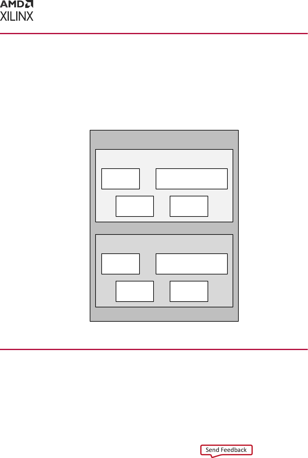
Application Development Using PetaLinux
Tools
Soware development ow in the PetaLinux tools environment involves many stages. To simplify
understanding, the following gure shows a chart with all the stages in the PetaLinux tools
applicaon development.
Figure 10: PetaLinux Tool-Based Software Development Flow
Petalinux Tools
Build Tools
Debug and Profile Tools
GNU Petalinux-Build
Yocto Make
GDB Petalinux-Boot
QEMU OProfile
X14815-063017
Linux Application Development Using Vitis
Xilinx soware design tools facilitate the development of Linux user applicaons. This secon
provides an overview of the development ow for Linux applicaon development.
The following gure illustrates the typical steps involved to develop Linux user applicaons using
the Vis soware plaorm.
Chapter 5: Software Development Flow
UG1137 (v2022.2) November 2, 2022 www.xilinx.com
Zynq UltraScale+ MPSoC: Software Developers Guide 45

Figure 11: Linux Application Development Flow
Invoke SDK
Create a Linux application
project
Build the Linux application
project
Software Application
Development
Profiling
Performance met?
Download Hardware
Bitstream to FPGA
Debug
Functionality
achieved?
Open / Create
SDK workspace
Adding an Application to
Linux file system
Yes
Yes
No
No
Boot Linux & set up target
connection
X14816-063017
Creating a Linux Application Project
You can create a C or C++ Linux applicaon project by using the New Applicaon Project wizard.
Chapter 5: Software Development Flow
UG1137 (v2022.2) November 2, 2022 www.xilinx.com
Zynq UltraScale+ MPSoC: Software Developers Guide 46

To create a project:
1. Click File → New → Applicaon Project. The New Applicaon Project dialog box appears.
2. Type a project name into the Project Name eld.
3. Select the locaon for the project. You can use the default locaon as displayed in the
Locaon eld by leaving the Use default locaon check box selected. Otherwise, click the
check box and type or browse to the directory locaon.
4. Select Next.
5. On the Select plaorm tab, select the Plaorm that has a Linux domain and click Next.
6. On the Domain window, select the domain from the Domain drop-down.
7. Select your preferred language: C or C++.
8. Oponally, select Linux System Root to specify the Linux sysroot path and select Linux
Toolchain to specify the Linux toolchain path.
9. Click Next to move to the Templates screen.
10. The Vis soware plaorm provides useful sample applicaons listed in the Templates dialog
box that you can use to create your project. The Descripon box displays a brief descripon
of the selected sample applicaon. When you use a sample applicaon for your project, the
Vis soware plaorm creates the required source and header les and linker script.
11. Select the desired template. If you want to create a blank project, select Empty Applicaon.
You can then add C les to the project, aer the project is created.
12. Click Finish to create your Linux applicaon project.
13. Click the
icon to generate or build the applicaon project.
Create a Hello World Application
Aer installing the Vis™ soware plaorm, the next step is to create a soware applicaon
project. Soware applicaon projects are the nal applicaon containers. The project directory
that is created contains (or links to) your C/C++ source les, executable output le, and
associated ulity les, such as the Makeles used to build the project.
Note: The Vis soware plaorm automacally creates a system project for you. A system project is a top-
level container project that holds all of the applicaons that can run in a system at the same me. This is
useful if you have many processors in your system, especially if they communicate with one another,
because you can debug, launch, and prole applicaons as a set instead of as individual items.
Build a Sample Application
This secon describes how to create a sample Hello World applicaon using an exisng template.
1. Launch the Vis soware plaorm.
2. Select a workspace directory for your rst project.
Chapter 5: Software Development Flow
UG1137 (v2022.2) November 2, 2022 www.xilinx.com
Zynq UltraScale+ MPSoC: Software Developers Guide 47

3. Click Launch. The welcome page appears.
4. Close the welcome page. The development perspecve opens.
5. Select File → New → Applicaon Project.
6. Enter a name in the Project name eld and click Next. The Select plaorm tab opens. You
should choose a plaorm for your project. You can either use a pre-supplied plaorm (from
Xilinx or another vendor), a previously created custom plaorm, or you can create one
automacally from an exported Vivado
®
hardware project.
7. On the Select plaorm tab, click the plaorm you just created and click Next. To use your
own hardware plaorm, click the
icon and add your plaorm to the list.
8. Select the system conguraon for your project and click Next. The Templates window
opens.
9. Select Hello World and click Next. Your workspace opens with the Explorer pane showing
the hello_world_system system project and the zcu102 plaorm project.
10. Right-click the system project and select Build Project. You have now built your applicaon
and the Console tab shows the details of the le and applicaon size.
Debug and Run the Application
Now that you have generated the executable binary, you can test it on a board. To run the
applicaon on the board, perform the following preliminary steps:
• Connect a JTAG cable to the computer.
• Set the Boot Mode switch of the board to JTAG mode.
• Connect a USB UART cable and setup your UART console.
• Power up the board.
1. Expand the system project and choose the applicaon project you want to debug. Right-click
the applicaon and select Debug As → Launch on Hardware (Single Applicaon Debug).
2. On the Conrm Perspecve Switch dialog, click Yes. The Vis IDE switches to the Debug
perspecve and the debugger stops at the entry to your main() funcon.
3. Using the commands in the toolbar, step through the applicaon. Aer you step through the
print() funcon, Hello World appears in the UART console.
Adding Driver Support for Custom IP in the PL
The Vis soware plaorm supports Linux BSP generaon for peripherals in the PS as well as
custom IP in the PL. When generang a Linux BSP, the Vis soware plaorm produces a device
tree, which is a data structure describing the hardware system that passes to the kernel when
you boot.
Chapter 5: Software Development Flow
UG1137 (v2022.2) November 2, 2022 www.xilinx.com
Zynq UltraScale+ MPSoC: Software Developers Guide 48

Device drivers are available as part of the kernel or as separate modules, and the device tree
denes the set of hardware funcons available and features enabled.
Addionally, you can add dynamic, loadable drivers. The Linux kernel supports these drivers.
Custom IP in the PL are highly congurable, and the device tree parameters dene both the set
of IP available in the system and the hardware features enabled in each IP.
See Chapter 3: Development Tools for addional overview informaon on the Linux Kernel and
boot sequence.
Chapter 5: Software Development Flow
UG1137 (v2022.2) November 2, 2022 www.xilinx.com
Zynq UltraScale+ MPSoC: Software Developers Guide 49

Chapter 6
Software Design Paradigms
The Xilinx
®
Zynq
®
UltraScale+™ MPSoC architecture supports heterogeneous mulprocessor
engines targeted at dierent tasks. The main approaches for developing soware to target these
processors are by using the following:
• Frameworks for Mulprocessor Development: Describes the frameworks available for
development on the Zynq UltraScale+ MPSoC.
• Symmetric Mulprocessing (SMP): Using SMP with PetaLinux is the most simple ow for
developing an SMP with a Linux plaorm for the Zynq UltraScale+ MPSoC.
• Asymmetric Mulprocessing (AMP): AMP is a powerful mode to use mulple processor
engines with precise control over what runs on each processor. Unlike SMP, there are many
dierent ways to use AMP. This secon describes two ways of using AMP with varying levels
of complexity.
The following secons describe these development methods in more detail.
Frameworks for Multiprocessor Development
Xilinx provides mulple frameworks for Zynq UltraScale+ MPSoCs to facilitate the applicaon
development on the heterogeneous processors and Xilinx 7 series FPGAs. These frameworks are
described as follows:
• Hypervisor Framework: Xilinx provides the Xen hypervisor, a crical item needed to support
virtualizaon on APU of Zynq UltraScale+ MPSoC. The Use of Hypervisors secon covers
more details.
• Authencaon Framework: The Zynq UltraScale+ MPSoC supports authencaon and
encrypon features as a part of authencaon framework. To understand more about the
authencaon framework, see Boot Time Security.
• TrustZone Framework: The TrustZone technology allows and maintains isolaon between
secure and non-secure processes within the same system. See this whitepaper for more
informaon.
Xilinx provides the trustzone support through the Trusted Firmware-A (TF-A) to maintain the
isolaon between secure and non-secure worlds. To understand more about TF-A, see Trusted
Firmware-A.
Chapter 6: Software Design Paradigms
UG1137 (v2022.2) November 2, 2022 www.xilinx.com
Zynq UltraScale+ MPSoC: Software Developers Guide 50

• Mulprocessor Communicaon Framework: Xilinx provides the OpenAMP framework for
Zynq UltraScale+ MPSoCs to allow communicaon between the dierent processing units.
For more details, see the Xilinx Quick Emulator User Guide: QEMU.
• Power Management Framework: The power management framework allows soware
components running across dierent processing units to communicate with the power
management unit.
Symmetric Multiprocessing (SMP)
SMP enables the use of mulple processors through a single operang system instance. The
operang system handles most of the complexity of managing mulple processors, caches,
peripheral interrupts, and load balancing.
The APU in the Zynq UltraScale+ MPSoCs contains four homogeneous cache coherent Arm
®
Cortex
®
-A53 processors that support SMP mode of operaon using an OS (Linux or VxWorks).
Xilinx and its partners provide operang systems that make it easy to leverage SMP in the APU.
The following diagram shows an example of Linux SMP with mulple applicaons running on a
single OS.
Figure 12: Example SMP Using Linux
APU
Arm
Cortex-A53
Arm
Cortex-A53
Arm
Cortex-A53
Arm
Cortex-A53
Linux Kernel in SMP
Application n
Thread 1
Thread 2
Thread n
Application 1
Thread 1
Thread 2
Thread n
X14837-063017
Chapter 6: Software Design Paradigms
UG1137 (v2022.2) November 2, 2022 www.xilinx.com
Zynq UltraScale+ MPSoC: Software Developers Guide 51

This would not be the best mode of operaon when there are hard, real-me requirements as it
ignores Linux applicaon core anity which should be available to developers with the exisng
Xilinx soware.
Asymmetric Multiprocessing (AMP)
AMP uses mulple processors with precise control over what runs on each processor. Unlike
SMP, there are many dierent ways to use AMP. This secon describes two ways of using AMP
with varying levels of complexity.
In AMP, a soware developer must decide what code has to run on each processor before
compiling and creang a boot image that includes the soware executable for each CPU. Using
AMP with the Arm Cortex-R5F processors (SMP is not supported in Cortex-R5F) in the RPU
enables developers to meet highly demanding, hard real-me requirements as opposed to so
real-me requirements.
You can develop the applicaons independently, and program those applicaons to communicate
with each other using inter-processing communicaon (IPC) opons. See this link to the
“Interrupts” chapter of the Zynq UltraScale+ Device Technical Reference Manual (UG1085) for
further descripon of this feature.
You can also apply this AMP method to applicaons running on MicroBlaze™ processors in the
PL or even in the APU. The following diagram shows an AMP example with applicaons running
on the RPU and the PL without any communicaon with each other.
Figure 13: AMP Example using Bare-Metal Applications Running on RPU and PL
MicroBlaze
Bare-metal
Application
Bare-metal
Application
Bare-metal
Application
RPU
PL
Arm
Cortex-R5F
Arm
Cortex-R5F
MicroBlaze
MicroBlaze
X19225-071317
OpenAMP
The OpenAMP framework provides mechanisms to do the following:
Chapter 6: Software Design Paradigms
UG1137 (v2022.2) November 2, 2022 www.xilinx.com
Zynq UltraScale+ MPSoC: Software Developers Guide 52

• Load and unload rmware
• Communicate between applicaons using a standard API
The following diagram shows an example of an OpenAMP and the hard real-me capabilies of
the RPU using the OpenAMP framework.
In this case, Linux applicaons running on the APU perform the loading and unloading of RPU
applicaons. This allows developers to load dierent processing dedicated algorithms to the RPU
processing engines as needed with very determinisc performance.
Figure 14: Example with SMP and AMP using OpenAMP Framework
X14839-063017
APU
Arm
Cortex-A53
Arm
Cortex-A53
Arm
Cortex-A53
Arm
Cortex-A53
Linux Kernel in SMP mode
RTOS
Kernel
Baremetal
Application
Application 1
Thread 1
Thread 2
Thread n
RPU
Arm
Cortex-R5F
Arm
Cortex-R5F
PL
MicroBlaze
MicroBlaze
RTOS
Kernel
Baremetal
Application
Baremetal
Application
Application n
Thread 1
Thread 2
Thread n
RPMsg
Open AMP
(APIs for loading/ Unloading
firmware, Message Passing)
RPMsg
See the Libmetal and OpenAMP for Zynq Devices User Guide (UG1186) for more informaon about
the OpenAMP Framework.
Virtualization with Hypervisor
The Zynq UltraScale+ MPSoCs include a hardware virtualizaon extension on the Arm Cortex-
A53 processors, interrupt controller, and Arm System MMU (SMMU) that provides exibility to
combine various operang system combinaons, including SMP and AMP, within the APU.
The following diagram shows an example of an SMP-capable OS, like Linux working along with
Real-Time Operang System (RTOS) as well as a bare metal applicaon using a single hypervisor.
This enables independent development of applicaons in their respecve mode of operaon.
Chapter 6: Software Design Paradigms
UG1137 (v2022.2) November 2, 2022 www.xilinx.com
Zynq UltraScale+ MPSoC: Software Developers Guide 53
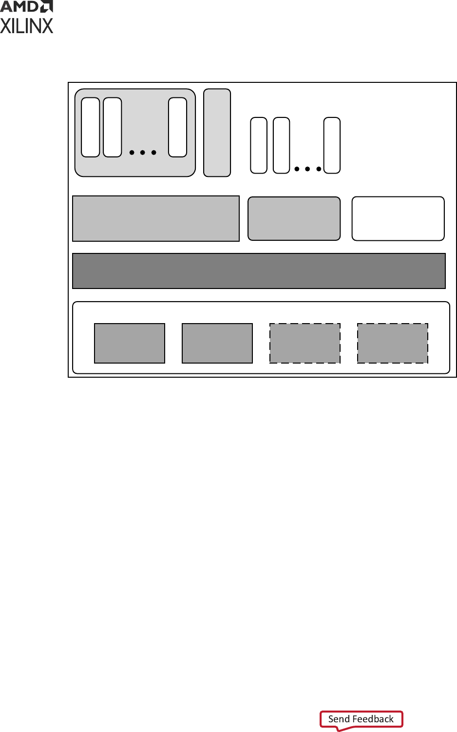
Figure 15: Example with Hypervisor
X14840-063017
Hypervisor
APU
Arm
Cortex-A53
Arm
Cortex-A53
Arm
Cortex-A53
Arm
Cortex-A53
Linux Kernel in
SMP mode
RTOS
Kernel
Baremetal
Application
Application 1
Thread 1
Thread 2
Thread n
Application n
Task 1
Task 2
Task n
Although the hardware virtualizaon included within Zynq UltraScale+ MPSoC and its
hypervisors allow the standard operang systems and their applicaons to funcon with low to
moderate eort, the addion of a hypervisor does bring design complexity to low-level system
funcons such as power management, FPGA bitstream management,
OpenAMP soware stack, and security accelerator access which must use addional underlying
layers of system rmware. Hence, Xilinx recommends that the developers must iniate early
eort into these aspects of system architecture and implementaon.
For more details on using Hypervisor like the Xen Hypervisor, see the MPSoC Xen Hypervisor
website.
Chapter 6: Software Design Paradigms
UG1137 (v2022.2) November 2, 2022 www.xilinx.com
Zynq UltraScale+ MPSoC: Software Developers Guide 54

Use of Hypervisors
Xilinx distributes a port for the Xen open source hypervisor in the Xilinx
Zynq UltraScale+ MPSoC. Xen hypervisor provides the ability to run mulple operang systems
on the same compung plaorm. Xen hypervisor, which runs directly on the hardware, is
responsible for managing CPU, memory, and interrupts. Mulple numbers of OS can run on top
of the hypervisor. These operang systems are called domains (also called as virtual machines
(VMs)).
The Xen hypervisor provides the ability to concurrently run mulple operang systems and their
standard applicaons with relave ease. However, Xen does not provide a generic interface
which gives the guest an operang system access to system funcons. Hence, you need to follow
the cauons menoned in this secon.
Xen hypervisor controls one domain, which is domain 0, and one or more guest domains. The
control domain has special privileges, such as the following:
• Capability to access the hardware directly
• Ability to handle access to the I/O funcons of the system
• Interacon with other virtual machines.
It also exposes a control interface to the outside world, through which the system is controlled.
Each guest domain runs its own OS and applicaon. Guest domains are completely isolated from
the hardware.
Running mulple Operang Systems using Xen hypervisor involves seng up the host OS and
adding one or more guest OS.
Note: Xen hypervisor is available as a selectable component within the PetaLinux tools; Xen hypervisor can
also be downloaded from Xilinx GIT. With Linux and Xen soware that is made available by Xilinx, it is
possible to build custom Linux guest conguraons. Guest OS other than Linux require addional soware
and eort from third-pares. See the PetaLinux Product Page for more informaon.
Chapter 6: Software Design Paradigms
UG1137 (v2022.2) November 2, 2022 www.xilinx.com
Zynq UltraScale+ MPSoC: Software Developers Guide 55

Chapter 7
System Boot and Configuration
Zynq
®
UltraScale+™ MPSoCs support the ability to boot from dierent devices such as a QSPI
ash, an SD card, a host with Device Firmware Upgrade ulity installed on it, or a NAND ash in
place. This chapter details the boong process using dierent boong devices in both secure and
non-secure modes.
Boot Process Overview
The plaorm management unit (PMU) and conguraon security unit (CSU) manage and perform
the mul-staged boong. You can boot the device in either secure (using authencated boot
image) or non-secure (using an unauthencated boot image) mode. The boot stages are as
follows:
• Pre-conguraon stage: The PMU primarily controls pre-conguraon stage that executes
PMU ROM to setup the system. The PMU handles all of the processes related to reset and
wake-up.
• Conguraon stage: This stage is responsible for loading the rst-stage boot loader (FSBL)
code for the PS into the on-chip RAM (OCM). It supports both secure and non-secure boot
modes. Through the boot header, you can execute FSBL on the Cortex
®
-R5F-0 / R5-1
processor or the Cortex
®
-A53 processor. The Cortex-R5F-0 processor also supports lock step
mode.
• Post-conguraon stage: Aer FSBL execuon starts, the Zynq UltraScale+ MPSoC enters
the post conguraon stage.
Boot Flow
There are two boot ows in the Zynq UltraScale+ MPSoC architecture: secure and non-secure.
The following secons describe some of the example boot sequences in which you bring up
various processors and execute the required boot tasks.
Note: The gures in these secons show the complete boot ow, including all mandatory and oponal
components.
Chapter 7: System Boot and Configuration
UG1137 (v2022.2) November 2, 2022 www.xilinx.com
Zynq UltraScale+ MPSoC: Software Developers Guide 56
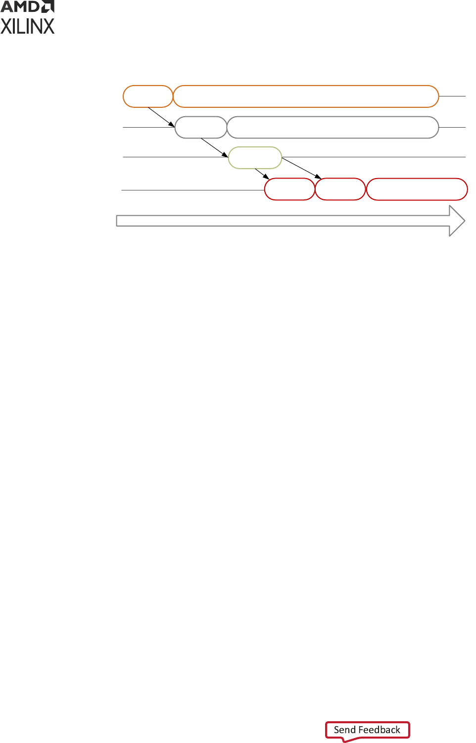
Figure 16: Boot Flow Example
Time
Release
CSU
Power
Monitoring
Load
FSBL
Tamper
Monitoring
PMU
CSU
RPU
FSBL
APU
U-Boot
Linux
ATF
X18969-062421
Non-Secure Boot Flow
In non-secure boot mode, the PMU releases the reset of the conguraon security unit (CSU),
and enters the PMU server mode where it monitors power. Aer the PMU releases the CSU
from reset, it loads the FSBL into OCM. PMU rmware runs from PMU RAM in parallel to FSBL
in OCM. FSBL is run on APU or RPU. FSBL runs from APU/RPU and TF-A; U-Boot and Linux run
on APU. Other boot conguraons allow the RPU to start and operate wholly independent of
the APU and vice-versa.
• On APU, TF-A will be executed aer the FSBL hands o to TF-A. TF-A hands o to a second
stage boot loader like U-Boot which executes and loads an operang system such as Linux.
• On RPU, FSBL hands o to a soware applicaon.
• Linux, in turn, loads the executable soware.
Note: The operang system manages the mulple Cortex-A53 processors in symmetric mul-processing
(SMP) mode.
Secure Boot Flow
In the secure boot mode, the PMU releases the reset of the conguraon security unit (CSU) and
enters the PMU server mode where it monitors power. Aer the PMU releases the CSU from
reset, the CSU checks to determine if authencaon is required by the FSBL or the user
applicaon.
The CSU does the following:
• Performs an authencaon check and proceeds only if the authencaon check passes. Then
checks the image for any encrypted parons.
• If the CSU detects parons that are encrypted, the CSU performs decrypon and loads the
FSBL into the OCM.
Chapter 7: System Boot and Configuration
UG1137 (v2022.2) November 2, 2022 www.xilinx.com
Zynq UltraScale+ MPSoC: Software Developers Guide 57

For more informaon on CSU, see the Conguraon Security Unit secon.
FSBL running on APU hands o to TF-A. FSBL running on RPU loads TF-A. In both the cases, TF-
A loads U-Boot which loads the OS. TF-A then executes the U-Boot and loads an OS such as
Linux. Then Linux, in turn, loads the executable soware. Similarly, FSBL checks for
authencaon and encrypon of each paron it tries to load. The parons are only loaded by
FSBL on successful authencaon and decrypon (if previously encrypted).
Note: In the secure boot mode, psu_coresight_0 is not supported as a stdout port.
Boot Image Creation
Bootgen is a tool that lets you stch binary les together and generate device boot images.
Bootgen denes mulple properes, aributes and parameters that are input while creang boot
images for use in a device.
The secure boot feature for devices uses public and private key cryptographic algorithms.
Bootgen provides assignment of specic desnaon memory addresses and alignment
requirements for each paron. It also supports encrypon and authencaon, described in the
Bootgen User Guide (UG1283). More advanced authencaon ows and key management opons
are discussed in the Using HSM Mode secon of Bootgen User Guide (UG1283), where Bootgen
can output intermediate hash les that can be signed oine using private keys to sign the
authencaon cercates included in the boot image. The program assembles a boot image by
adding header blocks to a list of parons.
Oponally, each paron can be encrypted and authencated with Bootgen. The output is a
single le that can be directly programmed into the boot ash memory of the system.
Various input les can be generated by the tool to support authencaon and encrypon as well.
Bootgen comes with both a GUI interface and a command line opon. The tool is integrated into
the soware development toolkit, Integrated Development Environment (IDE), for generang
basic boot images using a GUI, but the majority of Bootgen opons are command line-driven.
Command line opons can be scripted. The Bootgen tool is driven by a boot image format (BIF)
conguraon le, with a le extension of *.bif. Along with SoC, ACAP, and Bootgen has the
ability to encrypt and authencate parons for and later FPGAs, as described in FPGA Support.
In addion to the supported command and aributes that dene the behavior of a Boot Image,
there are ulies that help you work with Bootgen. Bootgen code is now available on Github.
Creating a Bootable Image
When a system project is selected, by running build, the Vis soware plaorm builds all
applicaons in the system project and creates a bootable image according to a pre-dened BIF or
an auto-generated BIF.
Chapter 7: System Boot and Configuration
UG1137 (v2022.2) November 2, 2022 www.xilinx.com
Zynq UltraScale+ MPSoC: Software Developers Guide 58

You can create bootable images using Bootgen. In the Vis™ IDE, the Create Boot Image menu
opon is used to create the boot image.
To create a bootable image, follow these steps:
1. Select the Applicaon Project in the Project Explorer view.
2. Right-click the applicaon and select Create Boot Image to open the Create Boot Image
dialog box.
3. Specify the boot loader and the parons.
Chapter 7: System Boot and Configuration
UG1137 (v2022.2) November 2, 2022 www.xilinx.com
Zynq UltraScale+ MPSoC: Software Developers Guide 59

4. Click Create Image to create the image and generate the BOOT.bin in the
<Application_project_name>/_ide/bootimage folder.
Boot Modes
Refer to this link to the “Boot and Conguraon” chapter of the Zynq UltraScale+ Device Technical
Reference Manual (UG1085) for a comprehensive table of the available boot modes.
QSPI24 and QSPI32 Boot Modes
The QSPI24 and QSPI32 boot modes support the following:
• x1, x2, and x4 read modes for single Quad SPI ash memory 24 (QSPI24) and single Quad SPI
ash memory 32 (QSPI32)
• x8 read mode for dual QSPI.
• Image search for MulBoot
• I/O mode for BSP drivers (no support in FSBL)
The bootROM searches the rst 256 Mb in x8 mode. In QSPI24 and QSPI32 boot modes (where
the QSPI24/32 device is < 128 Mb), to use MulBoot, place the mulple images so that they t
in memory locaons less than 128 Mb. The pin conguraon for QSPI24 boot mode is 0x1.
Note: QSPI dual stacked (x8) boot is not supported. Only QSPI Single Transmission Rate (STR) is supported.
Single Quad-SPI memory (x1, x2, and x4) is the only boot mode that supports execute-in-place (XIP).
To create a QSPI24/QSPI32 boot image, provide the following les to the Bootgen tool:
• An FSBL ELF
• A secondary boot loader (SBL), such as U-Boot, or a Cortex-R5F-0/R5-1 and/or a Cortex-A53
applicaon ELF
• Authencaon and encrypon key (oponal)
For more informaon on Authencaon and Encrypon, see Chapter 8: Security Features.
Bootgen generates the boot.mcs and a boot.bin binary le that you can write into the QSPI
ash using the ash writer. MCS is an Intel hex-formaed le that includes a checksum for
reliability.
Note: The pin conguraon for QSPI24 boot mode is 0x1 for qspi 24 and 0x2 for qspi32.
SD Boot Mode
SD boot (version 3.0) supports the following:
Chapter 7: System Boot and Configuration
UG1137 (v2022.2) November 2, 2022 www.xilinx.com
Zynq UltraScale+ MPSoC: Software Developers Guide 60

• FAT 16/32 le systems for reading the boot images.
• Image search for MulBoot with a maximum number 8,192 les are supported.
Note: exFAT is not supported for SD boot in FSBL and U-Boot.
The following gure shows an example for boong Linux in SD mode.
Figure 17: Booting in SD Mode
Bootgen Tool
Boot.bin
FAT 32
Kernel Image
Device tree file
Root file system
EXT 3
File system
Zynq
UltraScale+
MPSoc
0 1 0 1
Petalinux SDK
SDK
FSBL
U-Boot
A53 Image
KEY
.bif
SD card
Boot Mode
pins
KEY
Board
X14933-063017
To create an SD boot image, provide the following les to Bootgen:
• An FSBL ELF
• A Cortex-R5F-0/R5-1 and/or an Cortex-A53 applicaon ELF
• Oponal authencaon and encrypon keys
The Bootgen tool generates the boot.bin binary le. You can write the boot.bin le into an SD
card using a SD card reader.
In PetaLinux, do the following:
1. Build the Linux kernel image, device tree le, and the root le system.
2. Copy the les into the SD card.
The formaed SD card then contains the boot.bin, the kernel image, and the device tree le in
the FAT32 paron; the root le system resides in the EXT 4 paron.
IMPORTANT!
To boot from SD1, congure the boot pins to
0x5
. To boot from SD0, congure the boot
pins to
0x3
.To boot from SD with a level shier, congure the boot pins to
0xE
.
Chapter 7: System Boot and Configuration
UG1137 (v2022.2) November 2, 2022 www.xilinx.com
Zynq UltraScale+ MPSoC: Software Developers Guide 61
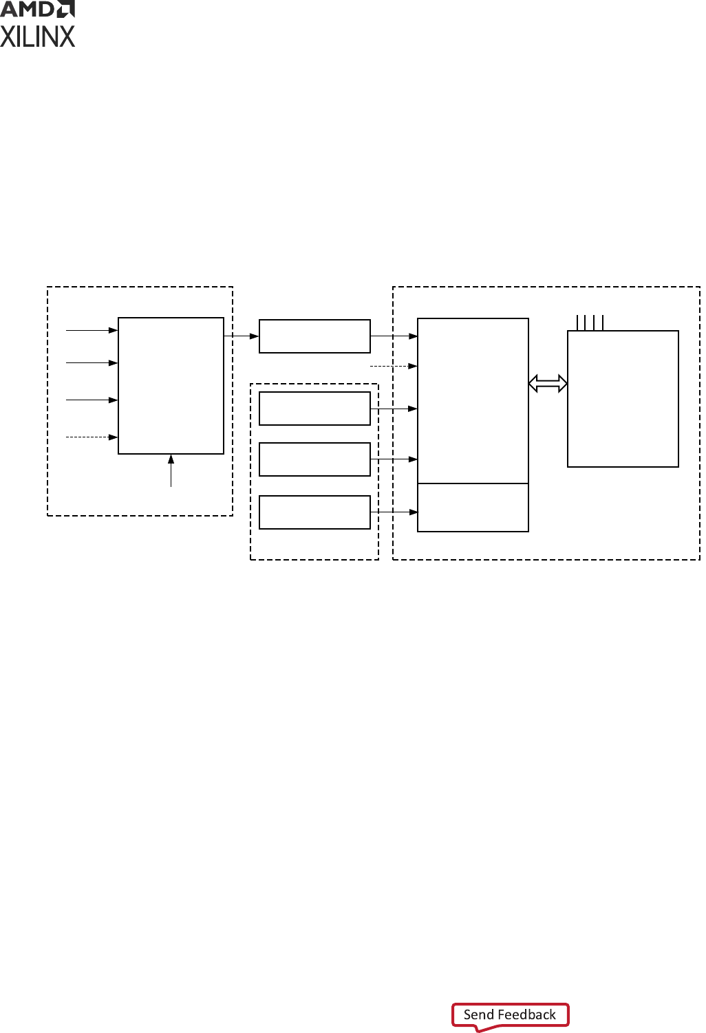
eMMC18 Boot Mode
eMMC18 boot (version 4.5) supports the following:
• FAT 16/32 le systems for reading the boot images.
• Image search for MulBoot with a maximum number of 8,192 les being supported.
The following gure shows an example for boong Linux in eMMC18 mode.
Figure 18: Booting in eMMC18 Mode
Bootgen Tool
Boot.bin
FAT 32
Kernel Image
Device tree file
Root file system
EXT 3
File system
Zynq
UltraScale+
MPSoc
0 1 1 0
PetaLinux SDK
SDK
FSBL
U-Boot
A53 Image
KEY
.bif
eMMC18 card
Boot Mode
pins
KEY
Board
X18971-071317
To create an eMMC18 boot image, provide the following les to Bootgen:
• An FSBL ELF
• A Cortex
®
-R5F-0/R5-1 and/or a Cortex
®
-A53 applicaon ELF
• Oponal authencaon and encrypon keys
The Bootgen tool generates the boot.bin binary le. You can write the boot.bin le into an
eMMC18 card using an eMMC18 card reader.
In PetaLinux, do the following:
• Build the Linux kernel image, device tree le, and the root le system.
• Copy the les into the eMMC18 card.
The formaed eMMC18 card then contains the boot.bin, the kernel image, and the device tree
les in the FAT32 paron; the root le system resides in the EXT4 paron.
Chapter 7: System Boot and Configuration
UG1137 (v2022.2) November 2, 2022 www.xilinx.com
Zynq UltraScale+ MPSoC: Software Developers Guide 62

NAND Boot Mode
The NAND boot only supports 8-bit widths for reading the boot images, and image search for
MulBoot. The following gure shows an example for boong Linux in NAND mode.
Figure 19: Booting in NAND Mode
Boot Header
FSBL
SBL
R5 Image
A53 Image
Bootgen
Tool
Flash
Writer
Flash
Boot.bin
eFuse
FSBL
R5 Image
A53 Image
.bif
SDK
JTAG
Key
QSPI
Board
NAND
Converter
NAND
image
Key
FSBL
Boot Pins
Zynq
UltraScale+
MPSoC
0100
X14934-071317
To create a NAND boot image, provide the following les to Bootgen:
• An FSBL ELF
• A Cortex-R5F-0/R5-1 applicaon ELF and/or an Cortex-A53 applicaon ELF
• Oponal authencaon/encrypon keys
The Bootgen tool generates the boot.bin binary le. You can then write the NAND bootable
image into the NAND ash using the ash writer
IMPORTANT!
To boot from NAND, congure boot pins to
0x4
.
JTAG Boot Mode
You can manually download any soware image needed for the PS and any hardware image on
the PL using JTAG. For JTAG boot mode sengs, see this link in the Zynq UltraScale+ Device
Technical Reference Manual (UG1085).
IMPORTANT!
Secure boot is not supported in the JTAG mode.
USB Boot Mode
The USB boot mode supports only USB 2.0. In USB boot mode, both the secure and non-secure
boot modes are supported. USB boot mode is not supported for DDR-less systems. Features like
Mulboot, fallback image, and XIP are not supported.
Chapter 7: System Boot and Configuration
UG1137 (v2022.2) November 2, 2022 www.xilinx.com
Zynq UltraScale+ MPSoC: Software Developers Guide 63

Note: USB boot mode is disabled by default in FSBL. To enable the USB boot mode, congure the
FSBL_USB_EXCLUDE_VAL to 0 in xfsbl_config.h le.
Table 13: USB Boot Mode Details
Pin Functionality
Mode pins 0x7
MIO pins MIO[63:52]
Non-secure Yes
Secure Yes
Signed Yes
Mode Slave
USB boot mode requires a host PC with dfu-uls installed on it. The host and device need to be
connected through a USB 2.0 or USB 3.0 cable. The host must contain one boot.bin to be loaded
by bootROM, which contains only fsbl.elf and another boot_all.bin to be loaded by
FSBL. On powering up the board in USB boot mode, issue the following commands:
• On Linux host:
• dfu-ul -D boot.bin: This downloads the le to the device, which is processed by
bootROM.
• dfu-ul -D boot_all.bin: This downloads the le to the device, which is processed by FSBL.
• On Windows host:
• dfu-ul.exe -D boot.bin: This downloads the le to the device, which is processed by
bootROM.
• dfu-ul.exe -D boot_all.bin: This downloads the le to the device, which is then processed
by FSBL.
The size limit of boot.bin and boot_all.bin are the sizes of OCM and DDR. The size of
OCM is 256 KB.
Secondary Boot Mode
There is a provision to have two boot devices in the Zynq UltraScale+ MPSoC architecture. The
primary boot mode is the boot mode used by bootROM to load FSBL and oponally PMU FW.
The secondary boot mode is the boot device used by FSBL to load all the other parons. The
supported secondary boot modes are QSPI24, QSPI32, SD0, eMMC, SD1, SD1-LS, NAND and
USB.
When using PS-PCIe
®
on ZU+ in Endpoint mode, running FSBL is enough to set up the block for
endpoint mode operaon. FSBL should be able to program the PS/PS-PCIe
®
and GTR within 100
ms. However, this doesn’t include PL-bitstream programming as including that would make this
greater than 100 ms.
Chapter 7: System Boot and Configuration
UG1137 (v2022.2) November 2, 2022 www.xilinx.com
Zynq UltraScale+ MPSoC: Software Developers Guide 64

IMPORTANT! If secondary boot mode is specied, it should be dierent from the primary boot device. For
example, if QSPI32 is the primary boot mode, QSPI24 cannot be the secondary boot mode. Instead, you
can have SD0, eMMC, SD1, SD1-LS, NAND, USB as secondary boot modes. All combinaons of boot
devices are supported as primary and secondary boot devices.
Note: By default, the secondary boot mode is the same as primary boot mode and there will be only one
boot image.
See What is Secondary Boot Mode in FSBL wiki page for more informaon.
Detailed Boot Flow
The plaorm management unit (PMU) in the Zynq UltraScale+ MPSoC is responsible for handling
the primary pre-boot tasks.
PMU ROM will execute from a ROM during boot to congure a default power state for the
device, inialize RAMs, and test memories and registers. Aer the PMU performs these tasks and
relinquishes system control to the conguraon security unit (CSU), it enters a service mode. In
this mode, the PMU responds to interrupt requests made by system soware through the
register interface or by hardware through the dedicated I/O to perform plaorm management
services.
Pre-Boot Sequence
The following table lists the tasks performed by the PMU in the pre-Boot sequence.
Table 14: Pre-Boot Sequence
Pre-Boot Task Description
0 Initialize MicroBlaze™ processor. Capture key states.
1 Scan, and clear LPD and FPD.
2 Initialize the System Monitor.
3 Initialize the PLL used for MBIST clocks.
4 Zero out the PMU RAM.
5 Validate the PLL. Configure the MBIST clock.
6 Validate the power supply.
7 Repair FPD memory (if required).
8 Zeroize the LPD and FPD and initialize memory self-test.
9 Power-down any disabled IPs.
10 Either release CSU or enter error state.
11 Enter service mode.
Chapter 7: System Boot and Configuration
UG1137 (v2022.2) November 2, 2022 www.xilinx.com
Zynq UltraScale+ MPSoC: Software Developers Guide 65

As soon as the CSU reset is released, it executes the CSU bootROM and performs the following
sequence:
1. Inializes the OCM.
2. Determines the boot mode by reading the boot mode register, which captures the boot-mode
pin strapping at the POR.
3. The CSU connues with the FSBL load and the oponal PMU rmware load. PMU rmware
is the soware that can be executed by the PMU unit. The code executes from the RAM of
the PMU. See Chapter 9: Plaorm Management for more informaon.
The following gure shows the detailed boot ow diagram.
Chapter 7: System Boot and Configuration
UG1137 (v2022.2) November 2, 2022 www.xilinx.com
Zynq UltraScale+ MPSoC: Software Developers Guide 66

Figure 20: Detailed Boot Flow Example
Power ON
PMU releases CSU Reset
Read Boot Mode Pins
Read Boot Header from
the Boot image
Check for
Authentication
Fallback bootDecrypt FSBL
Load FSBL to OCM
FSBL configures the PS
FSBL configures PL with
the bitstream
FSBL loads the RPU
software
FSBL loads the APU
software
FSBL Handoff to APU
software
Is FSBL
Authenticated?
YES
YES
NO
YES
NO
Is FSBL
Encrypted?
Authentication
Test passed?
Decryption
Fails?
NO
Fallback boot
YES
APU/RPU
CSU
PMU
X14935-070717
Chapter 7: System Boot and Configuration
UG1137 (v2022.2) November 2, 2022 www.xilinx.com
Zynq UltraScale+ MPSoC: Software Developers Guide 67

Disabling FPD in Boot Sequence
Perform the following to avoid an FPD lockout, where FPD Power is applied momentarily:
• Apply the power unl the compleon of bootROM execuon.
• To power down the FP during FSBL execuon, set FPD bit '22' of PMU_GLOBAL
REQ_PWRDWN_STATUS register.
• To bring the FP domain up in a later stage of the boot process, set the PMU_GLOBAL
REQ_PWRUP_STATUS bit to '22’.
Perform the following in cases where the FPD power is not applied before the FSBL boots
1. Power up the R5.
2. A register is set indicang the FPD is locked pending POR as the reset or clear sequence
cannot execute on the FPD.
3. R5 can read the FP locked status from PMU_GLOBAL REQ_ISO_STATUS register bit ‘4’.
4. At this stage, PMU_GLOBAL REQ_PWRUP_STATUS bit '22' will not be set.
5. To bring the FPD node back up, power must be supplied to the node and a POR needs to be
issued.
Setting FSBL Compilation Flags
You can set compilaon ags using the C/C++ sengs in the Vis FSBL project, as shown in the
following gure:
Note: There is no need to change any of the FSBL source les or header les to include these ags.
Chapter 7: System Boot and Configuration
UG1137 (v2022.2) November 2, 2022 www.xilinx.com
Zynq UltraScale+ MPSoC: Software Developers Guide 68

Figure 21: FSBL Debug Flags
The following table lists the FSBL compilaon ags.
Table 15: FSBL Compilation Flags
Flag Description
FSBL_DEBUG Prints basic information and error prints, if any.
FSBL_DEBUG_INFO Enables debug information in addition to the basic information.
FSBL_DEBUG_DETAILED Prints information with all data exchanged.
FSBL_NAND_EXCLUDE Excludes NAND support code.
FSBL_QSPI_EXCLUDE Excludes QSPI support code.
FSBL_SD_EXCLUDE Excludes SD support code.
SBL_SECURE_EXCLUDE Excludes authentication code and encryption code but not checksum
code.
FSBL_BS_EXCLUDE Excludes bitstream code.
FSBL_EARLY_HANDOFF_EXCLUDE Excludes early handoff related code.
FSBL_WDT_EXCLUDE Excludes WDT support code.
FSBL_PERF_EXCLUDE_VAL Excludes performance prints.
FSBL_A53_TCM_ECC_EXCLUDE_VAL Excludes TCM ECC Init for A53.
FSBL_PL_CLEAR_EXCLUDE_VAL Excludes PL clear unless boot.bin contains bitstream.
FSBL_PROT_BYPASS_EXCLUDE_VAL Excludes isolation configurations.
Chapter 7: System Boot and Configuration
UG1137 (v2022.2) November 2, 2022 www.xilinx.com
Zynq UltraScale+ MPSoC: Software Developers Guide 69

Table 15: FSBL Compilation Flags (cont'd)
Flag Description
8FSBL_PARTITION_LOAD_EXCLUDE_VAL Excluded partition loading.
FSBL_USB_EXCLUDE_VAL Excludes USB code.
This is set to 1 by default.
Set this value to 0 to enable USB boot mode.
FSBL_FORCE_ENC_EXCLUDE_VAL Excludes forcing encryption of all partitions when ENC_ONLY fuse is
programmed. By default, this is set to 0.
FSBL forces to enable encryption for all the partitions when ENC_ONLY
is programmed.
FSBL_DDR_SR_EXCLUDE_VAL DDR Excludes self refresh code.
FSBL_TPM_EXCLUDE_VAL Excludes TPM related code.
FSBL_PL_LOAD_FROM_OCM_EXCLUDE_VAL Excludes the code to load bitstream in chunks from OCM.
FSBL_UNPROVISIONED_AUTH_SIGN_EXCLUDE_VA
L
Excludes the code to load authenticated partitions as non-secure when
EFUSEs are not programmed and when boot header is not
authenticated.
See "I’m unable to build FSBL due to size issues, how can I reduce its footprint?" secon in FSBL
wiki page for more informaon.
Enabling Debug Prints
See FSBL wiki page for more informaon on debugging FSBL.
Fallback and MultiBoot Flow
In the Zynq
®
UltraScale+™ MPSoC, the CSU bootROM supports MulBoot and fallback boot
image search where the conguraon security unit CSU ROM or bootROM searches through the
boot device looking for a valid image to load. The sequence is as follows:
• BootROM searches for a valid image idencaon string (XLNX as image ID) at osets of 32
KB in the ash.
• Aer nding a valid idencaon value, validates the checksum for the header.
• If the checksum is valid, the bootROM loads the image. This allows for more than one image in
the ash.
In MulBoot:
• CSU ROM or FSBL or the user applicaon must iniate the boot image search to choose a
dierent image from which to boot.
• To iniate this image search, CSU ROM or FSBL updates the MulBoot oset to point to the
intended boot image, and generates a so reset by wring into the CRL_APB register.
The following gure shows an example of the fallback using the MulBoot ow.
Chapter 7: System Boot and Configuration
UG1137 (v2022.2) November 2, 2022 www.xilinx.com
Zynq UltraScale+ MPSoC: Software Developers Guide 70

Figure 22: Fallback using the MultiBoot Flow
Boot Header
Image 1
.
.
.
.
Boot Header
Image 2
0x100_0000
0x002_0000
0x000_0000
Boot Header 1
Image 1
.
.
.
.
.
Boot Header 2
Image 2
0x100_0000
0x002_0000
0x000_0000
.
.
.
.
0x001_0000
0x000_8000
0x001_8000
Multi-Boot
Offset=1
Multi-Boot
Offset=2
Multi-Boot
Offset=3
Multi-Boot
Offset=4
X14936-071217
Note: The same ow is applicable to both Secure and Non-secure boot methods.
In the example fallback boot ow gure, the following sequence occurs:
• Inially, the CSU bootROM loads the boot image found at 0x000_0000.
• If this image is found to be corrupted or the decrypon and authencaon fails, CSU
bootROM increments the MulBoot oset by one and searches for a valid boot image at
0x000_8000 (32 KB oset).
• If the CSU bootROM does not nd the valid idencaon value, it again increments the
MulBoot oset by 1, and searches for a valid boot image at the next 32 KB aligned address.
• The CSU bootROM repeats this unl a valid boot image is found or the image search limit is
reached. In this example ow, the next image is shown at 0x002_0000 corresponding to a
MulBoot oset value of four.
• In the example MulBoot ow, to load the second image that is at the address 0x002_0000,
MuBoot oset is updated to four by FSBL/CSU-ROM. When the MulBoot oset is
updated, so reset the system.
The following table shows the MulBoot image search range for dierent boong devices.
Chapter 7: System Boot and Configuration
UG1137 (v2022.2) November 2, 2022 www.xilinx.com
Zynq UltraScale+ MPSoC: Software Developers Guide 71

Table 16: Boot Devices and MultiBoot Image Search Range
Boot Device MultiBoot Image Search Range
QSPI Single (24-bit) 16 MB
QSPI Dual (24-bit) 32 MB
QSPI Single (32-bit) 256 MB
QSPI Dual (32-bit) 512 MB
NAND 128 MB
SD/EMMC 8,191 boot files
USB Not applicable
FSBL Build Process
Aer authencang and/or decrypng, the FSBL is loaded into OCM and handed o by the CSU
bootROM. First Stage Boot Loader congures the FPGA with a bitstream (if it exists) and loads
the Standalone (SA) Image or Second Stage Boot Loader image from the non-volale memory
(NAND/SD/eMMC/QSPI) to RAM(DDR/TCM/OCM). It takes the Cortex-R5F-0/R5F-1 processor
or the Cortex-A53 processor unit out of reset. It supports mulple parons. Each paron can
be a code image or a bitstream. Each of these parons, if required, will be authencated and/or
decrypted.
Note: If you are creang a custom FSBL, you should be aware that the OCM size is 256 KB and is available
to CSU bootROM. The FSBL size is close to 170 KB and it would t in the OCM. While using the USB boot
mode, you should make sure that the PMU rmware is loaded by the FSBL and not by the CSU bootROM.
This is because the size of boot.bin loaded by the CSU bootROM should be less than 256 KB.
Note: Users can load bitstream from OCM for non-encrypted cases even if DDR is present in the design.
By default, the FSBL_PL_LOAD_FROM_OCM_EXCLUDE_VAL value is set to 0 in xfsbl_config.h,
making the bitstream copy and load from DDR in the non-encrypted cases. By seng the
FSBL_PL_LOAD_FROM_OCM_EXCLUDE_VAL value to 1, the user can ensure that bitstream is loaded
from OCM in chunks and not from DDR. Also, if DDR is not present in the design, the bitstream is loaded
from OCM irrespecve of the FSBL_PL_LOAD_FROM_OCM_EXCLUDE_VAL value.
Creating a New Zynq UltraScale+ MPSoC FSBL
Application Project
To create a new Zynq UltraScale+ MPSoC FSBL applicaon in the Vis soware plaorm, do the
following:
1. Click File → New → Applicaon Project.
The New Applicaon Project dialog box appears.
2. In the Project Name eld, type a name for the new project.
Chapter 7: System Boot and Configuration
UG1137 (v2022.2) November 2, 2022 www.xilinx.com
Zynq UltraScale+ MPSoC: Software Developers Guide 72

3. Select the locaon for the project. To use the default locaon as displayed in the Locaon
eld, leave the Use default locaon check box selected. Otherwise, click to deselect the
check box, then type or browse to the directory locaon.
4. Select Create a new plaorm from hardware (XSA). The Vis IDE lists the all the available
pre-dened hardware designs.
5. Select any one hardware design from the list and click Next.
6. From the CPU drop-down list, select the processor for which you want to build the
applicaon. This is an important step when there are mulple processors in your design. In
this case you can either select psu_cortexa53_0 or psu_cortexr5_0.
7. Select your preferred language: C.
8. Select an OS for the targeted applicaon.
9. Click Next.
10. In the Templates dialog box, select the Zynq UltraScale+ MPSoC FSBL template.
11. Click Finish to create your applicaon project and board support package (if it does not exist).
Phases of FSBL Operation
FSBL operaon includes the following four stages:
• Inializaon
• Boot device inializaon
• Paron loading
• Hando
The following gure shows the stages of FSBL operaon:
Chapter 7: System Boot and Configuration
UG1137 (v2022.2) November 2, 2022 www.xilinx.com
Zynq UltraScale+ MPSoC: Software Developers Guide 73

Figure 23: Stages of FSBL
CSU
ROM
1.
Initializatio
n
2. Boot
Device
Initializatio
n
3. Partition
Copy,
Validation
4. Handoff
Applic
ation
wfe
PDR/RST
Handoff to
FSBL
Success
wfe
Error
Error
Error
JTAG
Boot
Error
SLCR RST
(FallBack)
Handof
f
Jtag Boot/
No Image
Partition
Completed
Partition Not
Completed
Fallback
Not Supported
FSBL Stage Diagram
FSBL Block Diagram
1. Initialization
1a. Get Reset Reason
1b. System Initialization
1c. Processor Initialization
1d. DDR Initialization
1e. Board Initialization
1f. Reset Validation
2. Boot Device Installation and
Header Validation
2a. Primary Boot Device
Initialization
2b. Header Validation
2c. Secondary Boot Device
Initialization
XFsbl Initialize()
XFsbl_BootDeviceInitAnd:
Validate()
3. Partition Copy Validation
3a. Partition Header
Validation
3b. Partition Copy
XFsbl_PartitionLoad()
4. Handoff
4a. PM Init
4b. Protection Config
4c. Handoff to CPUs
XFsbl_Handoff()
X19962-101917
Initialization
Inializaon consists of the following four internal stages:
XFsbl_SystemInit
This funcon powers up PL for 1.0 and 2.0 silicon and removes PS-PL isolaon. It inializes
clocks and peripherals as specied in psu-init. This funcon is not called in APU only reset.
Chapter 7: System Boot and Configuration
UG1137 (v2022.2) November 2, 2022 www.xilinx.com
Zynq UltraScale+ MPSoC: Software Developers Guide 74

Figure 24: FSBL System Initialization
Stage
1a
xFsbl_SystemInit()
System
Initialization
Home
XFsbl_PowerUpIsland()
XFsbl_IsolationRestore()
PowerupPL(Remove Isolation,
For 1.0 & 2.0 silicon)
psu_init()
*DDR, MIO, CLK, PLL Settings,
Peripheral, SERDES Initialization
Configuration
Successful?
no
Error
Lock
Down
yes
In MMUtable for A53 mask
DDR regions “memory”
Stage
1c
X19952-101917
XFsbl_ProcessorInit
Processor inializaon will start in this stage. It will set up the Instrucon and Data caches, L2
caches, MMU sengs, stack pointers in case of A53 and I/D caches, MPU sengs, memory
regions, stack pointers, and TCM sengs for R5-0. Most of these sengs will be performed in
BSP code inializaon. IVT vector is changed to the start of OCM for A53 and to start of TCM
(0x0 in lowvec and 0xffff0000 in highvec) in case of R5-0.
Chapter 7: System Boot and Configuration
UG1137 (v2022.2) November 2, 2022 www.xilinx.com
Zynq UltraScale+ MPSoC: Software Developers Guide 75

Figure 25: Processor Initialization
Stage
1c
Stage
1b
Partition
Initialization
Home
xFsbl_ProcessorInit()
Handoff from
CSUROM main()
· Configure
Memory
Regions, SP,
TCM (in BSP)
· Enable MPU I/D
Cache (In BSP)
· Copy IVT to
TCM (0x0)
· Change reset
address to TCM
(0x0)
Read Cluster ID
A9?
no
yes
· Configure SP
· Enable MMU, I/D
Cache, L2 Cache
· Change IVT to
start of OCM
XFsbl_RegisterHandlers()
Enable Exceptions
Register Exception Handlers
Stage
1d
X19954-101917
Initialize DDR
DDR would be inialized in this stage. This funcon is not called in Master only reset.
Chapter 7: System Boot and Configuration
UG1137 (v2022.2) November 2, 2022 www.xilinx.com
Zynq UltraScale+ MPSoC: Software Developers Guide 76

Figure 26: DDR Initialization
Stage
1d
Stage
1c
Stage
1e
DDR Initialization
DDR has ECC?
no
yes
ECC Initialization
of DDR
yes
Higher DDR
Preset!
Stage
1e
no
ECC Initialization
of higher DDR
Stage
1e
X19957-101917
XFsbl_BoardInit
This funcon performs required board specic inializaons. Most importantly, it congures GT
lanes and IIC.
Chapter 7: System Boot and Configuration
UG1137 (v2022.2) November 2, 2022 www.xilinx.com
Zynq UltraScale+ MPSoC: Software Developers Guide 77

Figure 27: Board Initialization
Stage
1e
Stage
1d
Board Init
no
Stage
1f
Initiate I2C driver
Board is
2cu102 or
2cu100
yes
Stage
1f
Configuration
programming I2C
USB
xxxxx
PCIE Reset for
2CU102
X19960-101917
Boot Device Initialization
XFsbl_PrimaryBootDeviceInit
This stage involves reading boot mode register to idenfy the primary boot device and inialize
the corresponding device. Each boot device driver provides init, copy and release funcons which
are inialized to DevOps funcon pointers in this stage.
Chapter 7: System Boot and Configuration
UG1137 (v2022.2) November 2, 2022 www.xilinx.com
Zynq UltraScale+ MPSoC: Software Developers Guide 78

Figure 28: Primary Boot Device Initialization
Stage
2a
Stage
1c
xFsbl_PrimaryBootDeviceInit()
yes
Home
Primary Boot Device
Initialization
XFsbl_InitWdt()
XFsbl_CsuDmainit()
Initialize
WDT,CSUDMA
drivers
BootMode==
(JTAG || PJTAG0 ||
PJTAG1)
yes
BootMode ==
(QSP124 || QSP132 || SD0
||EMMC||NAND||SD1 ||
SD1 with level shifter)
no
Wfe;
QSPI ?
no
Error
Lock
Down
yes
Configure QSPI
In Single/Dual/
Stacked mode
Configuration
Success?
no
Error
Lock
Down
NAND ?
yes
Configuration
Success?
no
no
Error
Lock
Down
SD/eMMC
yes
Configuration
Success?
no
no
Create boot
image name
yes
yes
no
no
Stage
2b
X19958-101917
Chapter 7: System Boot and Configuration
UG1137 (v2022.2) November 2, 2022 www.xilinx.com
Zynq UltraScale+ MPSoC: Software Developers Guide 79

XFsbl_ValidateHeader
Using the copy funcons provided, the FSBL reads the boot header aributes and image oset
address. It reads the EFUSE bit to check for authencaon. It reads the image header and
validates the image header table. It then reads the Paron Present Device aribute of image
header. A non-zero value indicates a secondary boot device. A zero value indicates that the
secondary boot device is the same as the primary boot device.
Figure 29: Validating Header
Stage
2b
Stage
2a
xFsbl_ValidateHeader()
Home
Header
Validation
XFsbl_ReadIma
geHeader() Read
Image Header
no
Error
Lock
Down
Validate Image
header
Populate handoff
parameter to ATF
Success?
no
Image Header
Table Validation
Successful?
yes
yes
Stage
3a
Image Header Validation
Checks
* No partitions present
* Num of partitions supported
* Start of Partition Header
offset Address check
* Image Header Table
Checksum
X19959-101917
Chapter 7: System Boot and Configuration
UG1137 (v2022.2) November 2, 2022 www.xilinx.com
Zynq UltraScale+ MPSoC: Software Developers Guide 80

XFsbl_SecondaryBootDeviceInit
This funcon is called in case of a non-zero value of Paron Present Device aribute of image
header table. It inializes the secondary boot device driver and the secondary boot device would
be used to load all parons by FSBL.
XFsbl_SetATFHandoffParams
TF-A is assumed to be the next loadable paron aer FSBL. It is capable of loading U-Boot and
secure OS and hence, it is passed a hando structure.
The rst paron of an applicaon will have a non-zero execuon address. All the remaining
parons of that applicaon will have 0 as execuon address. Hence look for the non-zero
execuon address for paron which is not the rst one and ensure the CPU is A53.
This funcon sets the hando parameters to the Trusted Firmware-A (TFA). The rst argument is
taken from the FSBL paron header. A pointer to the hando structure containing these
parameters is stored in the PMU_GLOBAL.GLOBAL_GEN_STORAGE6 register, which the TF-A
reads. The structure is lled with magic characters 'X', 'L', 'N', and 'X' followed by the total number
of parons and execuon address of each paron.
Partition Loading
XFsbl_PartitionHeaderValidation
Paron header is validated against various checks. All the required paron variables are
updated at this stage. If the paron owner is not FSBL, paron will be ignored and FSBL will
connue loading the other parons.
Chapter 7: System Boot and Configuration
UG1137 (v2022.2) November 2, 2022 www.xilinx.com
Zynq UltraScale+ MPSoC: Software Developers Guide 81

Figure 30: Partition Header Validation
Stage
3a
Stage
2b
xFsbl_PartitionHeaderValidation()
Partition Header
Validation
XFsbl_ValidateChecksum()
Validate Partition Header
Checksum ?
Partition
Parsing done
yes
Partition
Owner ==
FSBL
yes
Stage
3b
Home
Stage
4
Update Partition
Variables
Error
Lock
Down
no
no
Stage
3a
Check partition word
lengths for Plain Encrypted
and Autheticated
yes
XFsbl_thecheckvalidMemoryAddress()
Destination Load Address/Eexcuable address Checkt
* No DDR and address in DDR
* Address not in TCM, DRR, PL DDR
Error
Lock
Down
no
yes
Checksum word
offset, Image header
offset, Data word
offset check
yes
* Checksum type not supported
* Destination Cpu not supported
* Running in lockstep mode and destination cpu is r5-0/r5-1
* Destination Cpu same for 2 Images
* XIP Image and length
no
no
no
yes
xFsbl_ValidatePartitionHeader()
X19951-101917
Chapter 7: System Boot and Configuration
UG1137 (v2022.2) November 2, 2022 www.xilinx.com
Zynq UltraScale+ MPSoC: Software Developers Guide 82


Figure 31: Partition Copy
Stage
3b
Stage
3a
xFsbl_PartitionCopy()
yes
Home
Partition
Copy
If no Load address
specified, else
Adress = Load
adress
PS DDR
Present
Skip
Copying(DDRLess)
no
DestinationCPU ==
R5 && Load
address is in
TCM
Destination
Device == PL
no
· Update Load
address Map it
to high TCM
· Power up the
TCMs and
initialize TCM
& CC
yes
Running CPU is
R5 AND Partition is
Non secure Partition
AND Application
address overlaps
with IVT
Copy overlapping
Part of Partition to a
local buffer
yes
Trigger PMU0 IPI
and wait until PMU
Microblaze goes to
sleep before PMU
FW download
Destn Dev =
PMU
Copy
Successful?
yes
Stage
3a
PSOnly Reset
no
yes
Stage
3a
no
no
yes
X19950-101917
Chapter 7: System Boot and Configuration
UG1137 (v2022.2) November 2, 2022 www.xilinx.com
Zynq UltraScale+ MPSoC: Software Developers Guide 84

XFsbl_PartitionValidation
Paron will be validated based on the paron aributes. If checksum bit is enabled, then the
paron will be validated rst for checksum correctness and then, based on the authencaon
ag, it would be authencated. If encrypon ag is set, then the paron will be decrypted and
then copied to the desnaon.
Chapter 7: System Boot and Configuration
UG1137 (v2022.2) November 2, 2022 www.xilinx.com
Zynq UltraScale+ MPSoC: Software Developers Guide 85

Figure 32: Partition Validation Function
Xsecure_AesDecrypt()
Decrypt Image from DDR/
TCMP/PMU_RAM
To DDR/TCM/PMU_RAM
Stage
3c
Stage
3b
Checksum
enabled?
Stage xFsbl_PartitionValidation()
Checksum
Validation
Sucessful?
yes no
Home
Authenticaion
Enabled?
yes no
XFabl_Authentication()
Authentication Validation
Successful?
yes
no
Partition
Validation
(PS Image II
PMU firmware) &&
(Encrypted) ?
yes
no
yes
Decryption
Successful ?
Error
Xxx
xxxx
no
FsblHookBefore
BitstreamDownload
yes
Initialize PCAP
Interface
For 3.0 Ps version &
above Powerup PL
Encrypted
bitstream?
Xsecure_AesDecrypt()
Send bitstream via
CSUDMA_AES_to PCAP
yes
Send bitstream to
PCAP through
CSUDMA
PL Done
Successful?
Wait until PL Done
no
Error
Xxx
xxxx
Remove the Isolation
for PS-PL
Provide PS-PL
reset
FSBL Hook after
Bitstream download
Stage
4
PL Image?
yes
no
no
X19949-101917
Chapter 7: System Boot and Configuration
UG1137 (v2022.2) November 2, 2022 www.xilinx.com
Zynq UltraScale+ MPSoC: Software Developers Guide 86

Handoff
In this stage, protection_config funcons from psu_init will be executed and then, any
hando funconality is executed. Also PS-PL isolaon is removed uncondionally. R5 will be
brought out of reset if there is any paron supposed to run on its cores. R5-0/R5-1 will be
congured to boot in lowvec mode or highvec mode as per the sengs provided by you while
building the boot image. The hando address in lowvec mode is 0x0 and 0xffff0000 in
highvec mode. Lowvec/Highvec informaon should be specied by you while building the boot
image. Aer all the other PS images are done, then the running CPU will be handed o with an
update of the PC value. If there is no image to hand o for the running the CPU, FSBL will be in
wfe loop.
Any running processor cannot pass any parameters to any other processor. Any communicaon
between various parons can happen by reading from (or wring to) the PMU global registers.
Hando on the running processor involves updang Program Counter (PC) of the running
processor, as is done in the case of APU Reset. Hando to other processors involves updang
their PCs and bringing the processors out of reset.
XFsbl_PmInit
This funcon inializes and congures the Inter Processor Interrupts (IPI). It then writes the PM
conguraon object address to an IPI buer and triggers an IPI to the target. The PMU rmware
then reads and congures the device nodes as specied in the conguraon object.
Chapter 7: System Boot and Configuration
UG1137 (v2022.2) November 2, 2022 www.xilinx.com
Zynq UltraScale+ MPSoC: Software Developers Guide 87

Figure 33: PM Initialization
4a
Stage
3c
PM_INIT
Is PS-only
Reset
Remove PS-PL
isolation
Is APV-only
Reset
PM Init
4b
4c
yes
no
no
yes
X19946-101917
Protection Configuration
In this stage, protection_config funcons from psu_init will be executed. The applicaon
of protecon happens in this stage.
Chapter 7: System Boot and Configuration
UG1137 (v2022.2) November 2, 2022 www.xilinx.com
Zynq UltraScale+ MPSoC: Software Developers Guide 88

Figure 34: Protection Configuration
Disable tamper
responses
4b
4a
Protection Config
Is protection
byte met
psu-apply xxxxx3
psu-ocm-protection
4c
Stage
psu-protection
psu-protection mode
Enable tamper
response
yes
no
X19947-101917
Chapter 7: System Boot and Configuration
UG1137 (v2022.2) November 2, 2022 www.xilinx.com
Zynq UltraScale+ MPSoC: Software Developers Guide 89

Handoff
Hando on the running processor involves updang Program Counter (PC) of the running
processor, as is done in the case of APU Reset. Hando to other processors involves updang
their PCs and bringing the processors out of reset. A53 FSBL will bring R5 out of reset if there is
any paron to run on it. R5 will be congured to boot in lowvec mode or highvec mode as per
the sengs provided by you while building the boot image. The hando address in lowvec mode
is 0x0 and 0xffff0000 in highvec mode.
You must specify Lowvec/Highvec informaon while building the boot image. Aer all the other
PS images are done, then running the CPU image will be handed o to that cpu with an update
on the PC value. If there no image for the running CPU, it will be in wfe loop.
Figure 35: Handoff
Stage
4c
Stage
4b
xFsbl_Handoff()
Home
Handoff
Copy Arm
predefined code
to 0xffff0000
PS Image present?
yes
· Update Reset
vector address
at 0xFFFFFF00
· Take CPU out of
reset
Running CPU
handoff image
present ?
no
wfe
Disable
exceptions
yes
R5 ?
no
Update PC
yes
HANDOFF
· Copy the original
vector table to
TCM if required
· Update PC
X19948-101917
Chapter 7: System Boot and Configuration
UG1137 (v2022.2) November 2, 2022 www.xilinx.com
Zynq UltraScale+ MPSoC: Software Developers Guide 90

Supported Handoffs
The following table shows the various combinaons of handos that are supported in FSBL.
Table 17: Supported Handoffs
FSBL Application Processor Cores Execution Address
64-bit 64-bit All (i.e. A53-0, A53-1, A53-2, A53-3) Any Address
64-bit 32-bit A53-1, A53-2, A53-3 0x0
32-bit 32-bit A53-0 Any Address
32-bit 32-bit A53-1, A53-2, A53-3 0x0
32-bit 64-bit A53-1, A53-2, A53-3 Any Address
Error Lock Down
XFsbl_ErrorLockDown funcon handles errors in FSBL. This funcon is called whenever the
return value of a funcon is unsuccessful. This funcon updates error status register and then
loops indenitely, if fallback is not supported.
In case the boot mode supports fallback, MulBoot oset register is updated and then waits for a
WDT reset to occur. On reboot, bootROM and FSBL read the image from the new address
calculated from MulBoot oset, thus loading a new image.
Chapter 7: System Boot and Configuration
UG1137 (v2022.2) November 2, 2022 www.xilinx.com
Zynq UltraScale+ MPSoC: Software Developers Guide 91

Figure 36: Error Lock Down Function
XFsbl_ErrorLockDown()
Home
Update Error
Status Register
BootMode ==
( QSP124 || QSP132 || SD0
||EMMC|NAND|SD1 ||
SD1 with level shifter)
no
yes
Fallback not
supported by this
bootmode
XFsbl_HookBefor
eFallback() FSBL
Hook Before
Fallback
yes
Update Multiboot
Address register
wfe
SLCR Reset
X19953-101917
Miscellaneous Functions
The following funcons are available in FSBL:
XFsbl_PrintArray
This funcon prints enre array in bytes as specied by the debug type.
void XFsbl_PrintArray (u32 DebugType, const u8 Buf[], u32 Len, const char
*Str);
Table 18: XFsbl_PrintArray Parameters in FSBL
Parameters Description
DebugType Printing of the array is performed as defined by the debug
type.
Buf Pointer to the buffer to be printed
Len Length of the bytes to be printed
Str Pointer to the data that is printed
Chapter 7: System Boot and Configuration
UG1137 (v2022.2) November 2, 2022 www.xilinx.com
Zynq UltraScale+ MPSoC: Software Developers Guide 92

XFsbl_Strcpy
This funcon to copy the source string to the desnaon string.
char *XFsbl_Strcpy(char *DestPtr, const char *SrcPtr)
Table 19: XFsbl_Strcpy Parameters in FSBL
Parameters Description
DestPtr Pointer to the buffer to be printed
SrcPtr Pointer to the buffer containing the source string
XFsbl_Strcat
This funcon to append the second string to the rst string.
char* XFsbl_Strcat(char* Str1Ptr, const char* Str2Ptr)
Table 20: XFsbl_Strcat Parameters in FSBL
Parameters Description
Str1Ptr Pointer to the original string to which string pointed to by
Str2Ptr would be appended
Str2Ptr Pointer to the second string
XFsbl_Strcmp
This funcon compares strings.
s32 XFsbl_Strcmp( const char* Str1Ptr, const char* Str2Ptr)
Table 21: XFsbl_Strcmp Parameters in FSBL
Parameters Description
Str1Ptr Pointer to the first string
Str2Ptr Pointer to the second string
XFsbl_MemCpy
This funcon copies the memory contents pointed to by SrcPtr to the memory pointed to by
DestPtr. Len is number of bytes to be copied.
void* XFsbl_MemCpy(void * DestPtr, const void * SrcPtr, u32 Len)
Chapter 7: System Boot and Configuration
UG1137 (v2022.2) November 2, 2022 www.xilinx.com
Zynq UltraScale+ MPSoC: Software Developers Guide 93

Table 22: XFsbl_MemCpy Parameters in FSBL
Parameters Description
SrcPtr Pointer to the memory contents to be copied
DestPtr Pointer to the destination
Len Length of the bytes to be printed
XFsbl_PowerUpIsland
This funcon checks the power state of one or more power islands and powers them up if
required.
u32 XFsbl_PowerUpIsland(u32 PwrIslandMask)
Table 23: XFsbl_PowerUpIsland Parameters in FSBL
Parameters Description
PwrIslandMask Mask of island that needs to be powered up
XFsbl_IsolationRestore
This funcon requests isolaon restore through the PMU rmware.
u32 XFsbl_IsolationRestore(u32 IsolationMask);
Table 24: XFsbl_IsolationRestore Parameters in FSBL
Parameters Description
IsolationMask Mask of the entries for which isolation is to be restored
XFsbl_SetTlbAttributes
This funcon sets the memory aributes for a secon in the translaon table.
void XFsbl_SetTlbAttributes(INTPTR Addr, UINTPTR attrib);
Table 25: XFsbl_SetTlbAttributes Parameters in FSBL
Parameters Description
Addr Address for which the attributes are to be set
Attrib Attributes for the memory region
Chapter 7: System Boot and Configuration
UG1137 (v2022.2) November 2, 2022 www.xilinx.com
Zynq UltraScale+ MPSoC: Software Developers Guide 94

XFsbl_GetSiliconIdName
This funcon reads the CSU_ID_CODE register and calculates the SvdId of the device. It returns
the corresponding deviceID name.
const char *XFsbl_GetSiliconIdName(void);
XFsbl_GetProcEng
This funcon determines and returns the engine type. Currently only CG, EG, and EV engine
types are supported.
const char *XFsbl_GetProcEng(void);
XFsbl_CheckSupportedCpu
This funcon checks if a given CPU is supported by this variant of Silicon. Currently it checks if it
is CG part and disallows hando to A53_2/3 cores.
u32 XFsbl_CheckSupportedCpu(u32 CpuId);
Table 26: XFsbl_CheckSupportedCpu Parameters in FSBL
Parameters Description
Cpuld Checks if the processor is A53_2 or A53_3 or not.
XFsbl_AdmaCopy
This funcon copies data memory to memory using ADMA. You must take care of cache
invalidaon and ushing. ADMA also should be congured to simple DMA before calling this
funcon.
u32 XFsbl_AdmaCopy(void * DestPtr, void * SrcPtr, u32 Size);
Table 27: XFsbl_AdmaCopy Parameters in FSBL
Parameters Description
DestPtr Pointer to the destination buffer to which data needs to be
copied
SrcPtr Pointer to the source buffer from which data needs to be
copied
Size Number of bytes of data that needs to be copied
XFsbl_GetDrvNumSD
This funcon is used to obtain drive number based on design and boot mode.
u32 XFsbl_GetDrvNumSD(u32 DeviceFlags);
Chapter 7: System Boot and Configuration
UG1137 (v2022.2) November 2, 2022 www.xilinx.com
Zynq UltraScale+ MPSoC: Software Developers Guide 95

Table 28: XFsbl_GetDrvNumSD Parameters in FSBL
Parameters Description
Device flags Contains the boot mode information, that is, one of SD0,
SD1, eMMC, or SD1-LS boot modes
XFsbl_MakeSdFileName
This funcon returns the le name of the boot image. The name is deduced from the parameters.
void XFsbl_MakeSdFileName(char*XFsbl_SdEmmcFileName, u32 MultiBootReg, u32
DrvNum);
Table 29: XFsbl_MakeSdFileName Parameters in FSBL
Parameters Description
XFsbl_SdEmmcFileName Contains the final file name
Multiboot reg The value of the MultiBoot register gets appended to the file
name, if its value is non zero
DrvNum Differentiates between SD0 and SD1 logical drives
Hooks in FSBL
Hooks are the funcons that can be dened by you. FSBL provides blank funcons and executes
them from certain strategic locaons. The following table shows the currently available hooks.
Table 30: Hooks in FSBL
Hook Purpose/Location Hook Function Name
Before PL bitstream loading XFsbl_HookBeforeBSDownload()
After PL bitstream loading XFsbl_HookAfterBSDownload()
Before (the first) Handoff (to any application) XFsbl_HookBeforeHandoff()
Before fallback XFsbl_HookBeforeFallback()
To add more initialization code, in addition to that in psu_init
or to replace psu_init with custom initialization
XFsbl_HookPsuInit(()
See FSBL wiki page for more informaon on FSBL.
Chapter 7: System Boot and Configuration
UG1137 (v2022.2) November 2, 2022 www.xilinx.com
Zynq UltraScale+ MPSoC: Software Developers Guide 96

Using the Ethernet-Based Recovery Tool
The SOM soluon stack includes an Ethernet-based recovery mode that can be used with an
applicaon on a host PC to provide a full factory QSPI image reset/reload mechanism. The
recovery tool will be maintained in a reserved secon of the QSPI memory. Ethernet-based
recovery was selected over USB as many security minded customers prefer to disable the USB
but are using Ethernet in their applicaons. The Ethernet recovery applicaon is an applicaon
that runs a simplied Ethernet stack for interacng with a customer/engineer’s host machine (for
example, a laptop) to allow a manual update/overwrite of Image A and Image B on QSPI on SOM.
Ethernet-based recovery requires no incremental tools on your PC besides a web browser. Your
PC must have the new rmware binary le in its local le-system. You should be able to handle
downloading the associated Xilinx factory boot le updates from a Xilinx repository, and the on-
target rmware will handle the mapping of a given le to physical address and the act of wring
to ash. Image recovery ulity uses a xed IP address of 192.168.0.111.
The Ethernet-based recovery tool is capable of reading the sideband control EEPROMs to verify
the make and model of the SOM. The Ethernet factory fallback/recovery process is iniated by
holding the FWUEN buon during a power on reset sequence. The tool requires the rmware
update buon to be depressed to over-write any rmware contents. It updates the
corresponding A/B persistent registers to an appropriate state.
To use the Ethernet-based recovery tool, follow these steps:
1. Hold the rmware update enable (FWUEN) buon when powering on the device.
2. Connect the PC to the KV260 Starter Kit via Ethernet as shown in the following gure.
3. Set the PC to a stac IP that is on the same subnet as the recovery tool (192.168.0.xyz), but
not the same IP address.
4. Use a web-browser (for example, Chrome or Firefox) to enter the URL hp://192.168.0.111
for access to the Ethernet-based recovery tool.
Chapter 7: System Boot and Configuration
UG1137 (v2022.2) November 2, 2022 www.xilinx.com
Zynq UltraScale+ MPSoC: Software Developers Guide 97

5. Use the GUI to update either the A or B boot rmware parons with a boot.bin le from
the le system on the PC.
The Ethernet recovery tool interface is shown in the following gure.
Figure 37: Ethernet Recovery Tool
Chapter 7: System Boot and Configuration
UG1137 (v2022.2) November 2, 2022 www.xilinx.com
Zynq UltraScale+ MPSoC: Software Developers Guide 98

Chapter 8
Security Features
This chapter details the Zynq
®
UltraScale+™ MPSoC features that you can leverage to address
security during boot me and run me of an applicaon. The Secure Boot mechanism is
described in detail in this link to the Security chapter of the Zynq UltraScale+ Device Technical
Reference Manual (UG1085).
The system protecon units (SPU) provide the following hardware features for run-me security
of an applicaon running on Zynq UltraScale+ MPSoCs:
• Xilinx Memory Protecon Unit
• Xilinx Peripheral Protecon Unit
• System Memory Management Unit
• A53 Memory Management Unit
• R5 Memory Protecon Unit
One of the runme security features is access controls on the PMU and CSU global registers
from Linux. These registers are classied into two lists: The white list (accessible all the me by
default) and the black list (accessible only when a compile me ag is set). For more details, see
CSU/PMU Register Access.
Boot Time Security
This secon details the various boot image formats for authencaon and encrypon.
IMPORTANT!
For Zynq MPSoC, when RSA_EN eFUSE is not programmed and
BOOT.BIN
does not have
BH_AUTH enabled, FSBL can load bin as non-secure even if the parons are authencated. It is a new
feature in 2021.1, which is disabled by default. To enable it, set
FSBL_UNPROVISIONED_AUTH_SIGN_EXCLUDE_VAL to 0 in xfsbl_cong.h
Encryption
Zynq UltraScale+ MPSoCs has a 256-bit AES-GCM hardware engine that supports condenality
of your boot images, and can also be used post-boot to encrypt and decrypt data.
Chapter 8: Security Features
UG1137 (v2022.2) November 2, 2022 www.xilinx.com
Zynq UltraScale+ MPSoC: Software Developers Guide 99

The AES cryptographic engine has access to a diverse set of key sources. For more informaon
on the key sources, see Zynq UltraScale+ Device Technical Reference Manual (UG1085).
The red key is used to encrypt the image. During the generaon of the boot le (BOOT.bin), the
red key, and the inializaon vector (IV) must be provided to the Bootgen tool in .nky le
format.
PMU rmware can be loaded by CSU bootROM or FSBL.
IMPORTANT! If both the FSBL and PMU rmware are encrypted, the PMU rmware must be loaded by
the FSBL (and not the CSU bootROM) to avoid reusing the AES Key/IV pair. For more informaon, see
Xilinx Answer 70622.
The following BIF le is an example encrypted image, where PMU rmware is loaded by FSBL:
the_ROM_image:
{
[aeskeyfile] bbram.nky [keysrc_encryption] bbram_red_key
[bootloader, encryption=aes, destination_cpu=a53-0] ZynqMP_Fsbl.elf
[destination_cpu = pmu, encryption=aes] pmufw.elf
}
BIF File with BBRAM Red Key
The following BIF le sample shows the red key stored in BBRAM:
the_ROM_image: { [aeskeyfile] bbram.nky
[keysrc_encryption] bbram_red_key
[bootloader, encryption=aes, destination_cpu=a53-0] ZynqMP_Fsbl.elf
[destination_cpu = a53-0, encryption=aes] App_A53_0.elf
}
BIF File with eFUSE Red Key
The following BIF le sample shows the red key stored in eFUSE.
the_ROM_image: { [aeskeyfile] efuse.nky
[keysrc_encryption] efuse_red_key
[bootloader, encryption=aes, destination_cpu=a53-0] ZynqMP_Fsbl.elf
[destination_cpu = a53-0, encryption=aes] App_A53_0.elf
}
Chapter 8: Security Features
UG1137 (v2022.2) November 2, 2022 www.xilinx.com
Zynq UltraScale+ MPSoC: Software Developers Guide 100

BIF File with an Operational Key
For creang a boot image using Bootgen with an operaonal key (op key), you must provide the
tool with the operaonal key, along with the red key and IV in an .nky le. Bootgen places this
operaonal key in a header and encrypts it with the device red key. The result is what is called an
encrypted secure header. The main advantage of this is that it minimizes the use of the device
key, thus liming its exposure. For more details, refer to “Minimizing Use of the AES Boot Key
(OP Key Opon)” in the Zynq UltraScale+ Device Technical Reference Manual (UG1085).
the_ROM_image:
{
[aeskeyfile] bbram.nky [fsbl_config] opt_key [keysrc_encryption]
bbram_red_key
[bootloader, encryption=aes, destination_cpu=a53-0] ZynqMP_Fsbl.elf
[destination_cpu = a53-0, encryption=aes] App_A53_0.elf
}
Using Op Key to Protect the Device Key in a Development Environment
The following steps provide a soluon in a scenario where two development teams Team-A
(secure team), which manages the secret red key and Team-B (non-secure team) work
collaboravely to build an encrypted image without sharing the secret red key. Team-A manages
the secret red key. Team-B builds encrypted images for development and test. However, it does
not have access to the secret red key.
Team-A encrypts the boot loader with the device key (using the Op Key opon) and delivers the
encrypted bootloader to Team-B. Team-B encrypts all the other parons using the Op Key.
Team-B takes the encrypted parons that they created and the encrypted boot loader they
received from the Team-A and uses Bootgen to ‘stch’ everything together into a single
boot.bin.
The following procedures describe the steps to build an image:
Procedure 1
In the inial step, Team-A encrypts the boot loader with the device key using the opt_key opon,
delivers the encrypted boot loader to Team-B. Now, Team-B can create the complete image at a
go with all the parons and the encrypted boot loader using the operaonal key as device key.
1. Encrypt boot loader with device key:
bootgen -arch zynqmp -image stage1.bif -o fsbl_e.bin -w on -log error
Chapter 8: Security Features
UG1137 (v2022.2) November 2, 2022 www.xilinx.com
Zynq UltraScale+ MPSoC: Software Developers Guide 101

Example stage1.bif:
stage1:
{
[aeskeyfile] aes.nky
[fsbl_config] opt_key
[keysrc_encryption] bbram_red_key
[bootloader,destination_cpu=a53-0,encryption=aes]fsbl.elf
}
Example aes.nky for stage1:
Device xc7z020clg484;
Key 0 AD00C023E238AC9039EA984D49AA8C819456A98C124AE890ACEF002100128932;
IV 0 F7F8FDE08674A28DC6ED8E37;
Key Opt 229C993D1310DD27B6713749B6D07FCF8D3DCA01EC9C64778CBAF457D613508F;
2. Aach the encrypted boot loader and rest of the parons with the operaonal key as device
key to form a complete image:
bootgen -arch zynqmp -image stage2a.bif -o final.bin -w on -log error
Example of stage2.bif:
stage2:
{
[aeskeyfile] aes-opt.nky
[bootimage]fsbl_e.bin
[destination_cpu=a53-0,encryption=aes]hello.elf
[destination_cpu=a53-1,encryption=aes]hello1.elf
}
Example aes-opt.nky for stage2:
Device xc7z020clg484;
Key 0 229C993D1310DD27B6713749B6D07FCF8D3DCA01EC9C64778CBAF457D613508F;
IV 0 F7F8FDE08674A28DC6ED8E37;
Procedure 2
In the inial step, Team-A encrypts the boot loader with the device key using the opt_key opon
and delivers the encrypted boot loader to Team-B. Now, Team-B can create encrypted images for
each paron independently, using the operaonal key as the device key. Finally, Team-B can use
Bootgen to stch all the encrypted parons and the encrypted boot loader, to get the complete
image.
1. Encrypt boot loader with device key:
bootgen -arch zynqmp -image stage1.bif -o fsbl_e.bin -w on -log error
Chapter 8: Security Features
UG1137 (v2022.2) November 2, 2022 www.xilinx.com
Zynq UltraScale+ MPSoC: Software Developers Guide 102

Example stage1.bif:
stage1:
{
[aeskeyfile] aes.nky
[fsbl_config] opt_key
[keysrc_encryption] bbram_red_key
[bootloader,destination_cpu=a53-0,encryption=aes]fsbl.elf
}
Example aes.nky for stage1:
Device xc7z020clg484;
Key 0 AD00C023E238AC9039EA984D49AA8C819456A98C124AE890ACEF002100128932;
IV 0 F7F8FDE08674A28DC6ED8E37;
Key Opt 229C993D1310DD27B6713749B6D07FCF8D3DCA01EC9C64778CBAF457D613508F;
2. Encrypt the rest of the parons with operaonal key as device key:
bootgen -arch zynqmp -image stage2a.bif -o hello_e.bin -w on -log error
Example of stage2a.bif:
stage2a:
{
[aeskeyfile] aes-opt.nky
[destination_cpu=a53-0,encryption=aes]hello.elf
}
bootgen -arch zynqmp -image stage2b.bif -o hello1_e.bin -w on -log error
Example of stage2b.bif:
stage2b:
{
[aeskeyfile] aes-opt.nky
[destination_cpu=a53-1,encryption=aes]hello1.elf
Example of aes-opt.nky for stage2a and stage2b:
Device xc7z020clg484;
Key 0 229C993D1310DD27B6713749B6D07FCF8D3DCA01EC9C64778CBAF457D613508F;
IV 0 F7F8FDE08674A28DC6ED8E37;
3. Use Bootgen to stch the above to form a complete image:
Example of stage3.bif:
stage3:
{
[bootimage]fsbl_e.bin [bootimage]hello_e.bin [bootimage]hello1_e.bin
}
Note: Key Opt of aes.nky is same as Key 0 in aes-opt.nky and IV 0 must be same in both nky les.
Chapter 8: Security Features
UG1137 (v2022.2) November 2, 2022 www.xilinx.com
Zynq UltraScale+ MPSoC: Software Developers Guide 103

BIF File for Black Key Stored in eFUSE
For customers who would like to have the device key stored encrypted when not in use, the
physical unclonable funcon (PUF) can be used. Here, the actual red key is encrypted with the
PUF key encrypon key (KEK), which is an encrypon key that is generated by the PUF. The
device will decrypt the black key to get the actual red key, so you need to provide the KEK details
in BIF, such as shuer value, KEK IV to Bootgen. The black key can be stored in either eFUSE or
the Boot Header. Shuer value indicates the me for which the oscillator values can be captured
for PUF. This value must always be 0x100005E.
For more details, refer to “Storing Keys in Encrypted Form (Black)” in the Zynq UltraScale+ Device
Technical Reference Manual (UG1085).
The following BIF example shows storage of the black key in eFUSE.
the_ROM_image:
{
[pskfile]PSK.pem
[sskfile]SSK.pem
[aeskeyfile]red.nky
[keysrc_encryption] efuse_blk_key
[fsbl_config] shutter=0x0100005E
[auth_params] ppk_select=0
[bootloader, encryption = aes, authentication = rsa,
destination_cpu=a53-0]fsbl.elf
[bh_key_iv] black_key_iv.txt
}
BIF File for Black Key Stored in Boot Header
The following BIF le sample shows boot header black key encrypon:
the_ROM_image:
{
[aeskeyfile] redkey.nky
[keysrc_encryption] bh_blk_key
[bh_keyfile] blackkey.txt
[bh_key_iv] black_key_iv.txt
[fsbl_config] pufhd_bh , puf4kmode , shutter=0x0100005E, bh_auth_enable
[pskfile] PSK.pem
[sskfile] SSK.pem
[bootloader,authentication=rsa , encryption=aes,
destination_cpu=a53-0]fsbl.elf
[puf_file]hlprdata4k.txt
}
Note: Authencaon of boot image is compulsory for using black key encrypon.
To generate or program the eFUSEs with the back key, see Programming BBRAM and eFUSEs
(XAPP1319).
Chapter 8: Security Features
UG1137 (v2022.2) November 2, 2022 www.xilinx.com
Zynq UltraScale+ MPSoC: Software Developers Guide 104

BIF File for Obfuscated Form (Gray) Key Stored in eFUSE
If you would like to have the device key store in obfuscated form, you can encrypt the actual red
key with the family key which is an encrypon key. Device will decrypt the obfuscated key to get
the actual red key. Hence, you need to provide the required inputs to Bootgen. The obfuscated
key can be stored in either eFUSE or the Boot Header.
For more details, see Storing Keys in Obfuscated Form (Gray) secon in the Zynq UltraScale+
Device Technical Reference Manual (UG1085).
Note: The family key is the same for all devices within a given Zynq UltraScale+ MPSoCs family. This
soluon allows you to distribute the obfuscated key to contract manufacturer's without disclosing the
actual user key.
The following example shows storage of the obfuscated key in eFUSE:
the_ROM_image:
{
[aeskeyfile] red.nky
[keysrc_encryption] efuse_gry_key
[bh_key_iv] bhkeyiv.txt
[bootloader, encryption=aes, destination_cpu=a53-0] fsbl.elf
}
The following example shows storage of the obfuscated form (gray) key in boot header:
the_ROM_image:
{
[aeskeyfile] red.nky [keysrc_encryption] bh_gry_key [bh_key_iv]
bhkeyiv.txt
[bh_keyfile] bhkey.txt
[bootloader, encryption=aes, destination_cpu=a53-0] fsbl.elf
}
To Generate Obfuscated Key with Family Key:
Use Xilinx tools (Bootgen) to create the Obfuscated key. However, the family key is not
distributed with the Xilinx development tools. It is provided separately. The family key received
from Xilinx should be provided in the bif as shown in the example below.
IMPORTANT!
To receive the family key, please contact secure.solu[email protected].
Sample bif to generate Obfuscated key:
all:
{
[aeskeyfile] aes.nky
[familykey] familyKey.cfg
[bh_key_iv] bhiv.txt
}
For more informaon, see Bootgen User Guide (UG1283).
Chapter 8: Security Features
UG1137 (v2022.2) November 2, 2022 www.xilinx.com
Zynq UltraScale+ MPSoC: Software Developers Guide 105

Using Bootgen to Generate Keys
If you are using Bootgen to create keys, NIST approved KDF is used, which is Counter Mode KDF
with CMAC as the PRF.
With a Single Key/IV pair:
• If seed is specied - Key Generaon is based on Seed.
• If seed is NOT specied - Key Generaon is based on Key0.
IMPORTANT! For producon devices, make sure that the Seed or Key0 has been generated by a
cryptographically strong generator such as a true random number generator.
If an empty le is menoned, Bootgen generates a seed with me based randomizaon. This is
not a standard like the KDF. This seed will in turn be the input for KDF to generate the Key/IV
pairs.
BIF File with Multiple AESKEY Files
The following BIF le samples show the encrypons using aeskey les:
One AES Key / Partition
You may specify mulple .nky les, one for each paron in the image. The parons are
encrypted using the key that is specied before the paron.
sample_bif:
{
[aeskeyfile] test1.nky
[bootloader, encryption=aes] fsbl.elf
[aeskeyfile] test2.nky
[encryption=aes] hello.elf
[aeskeyfile] test3.nky
[encryption=aes] app.elf
}
The fsbl.elf paron is encrypted using the keys from test1.nky le. If you assume that
the hello.elf le has two parons since it has two loadable secons, then both the
parons are encrypted using keys from test2.nky le. The app.elf paron is encrypted
using keys from test3.nky le.
Chapter 8: Security Features
UG1137 (v2022.2) November 2, 2022 www.xilinx.com
Zynq UltraScale+ MPSoC: Software Developers Guide 106

One AES Key / Each Partition (Multiple Loadable Sections Scenario)
You may specify mulple .nky les, one for each paron in the image. The parons are
encrypted using the key that is specied before the paron. You are allowed to have unique key
les for each of the paron created due to mulple loadable secons by having key le names
appended with ‘.1’, ‘.2’...’.n’ in the same directory of the key le meant for that paron.
sample_bif:
{
[aeskeyfile] test1.nky
[bootloader, encryption=aes] fsbl.elf
[aeskeyfile] test2.nky
[encryption=aes] hello.elf
[aeskeyfile] test3.nky
[encryption=aes] app.elf
}
The fsbl.elf paron is encrypted using the keys from test1.nky le. Assume that the
hello.elf le has three parons since it has three loadable secons, and hello.elf.0 is
encrypted using the keys from test2.nky le, hello.elf.1 is encrypted using the keys from
test2.1.nky, and hello.elf.2 is encrypted using the keys from test2.2.nky le. The
app.elf paron is encrypted using keys from test3.nky le.
Using the same .nky le across mulple parons, reuses the AES Key and AES Key/IV Pair in
each paron. Using the AES key across mulple parons increases the exposure of the key
and violates NIST. 800-38D. To avoid the re-use of AES Key/IV pair, Bootgen increments the IV
with the paron number. To avoid the re-use of both AES Key and AES Key/IV pair, Bootgen
allows you to provide mulple .nky les, one for each paron.
IMPORTANT!
To avoid key re-use, support for single nky le across mulple parons will be deprecated.
CAUTION! Using a single
.nky
le with mulple parons means that the same key is being used in
each paron, which violates NIST. 800-38D. A warning is issued in the current release with the plan to
generate an error in future releases.
Note: Key0/IV0 - should be the same in all the nky les.
If you specify mulple keys and if the number of keys are less than the number of blocks to be
encrypted, the Bootgen is ERRORED OUT.
If you need to specify mulple Key/IV pairs, you must specify (number-of-blocks+1) pairs. The
extra Key/IV pair is for SH. Ex: If blocks=4;8;16 - you have to specify 4+1=5 Key/IV pairs.
Chapter 8: Security Features
UG1137 (v2022.2) November 2, 2022 www.xilinx.com
Zynq UltraScale+ MPSoC: Software Developers Guide 107

Authentication
The SHA hardware accelerator included in the Zynq UltraScale+ MPSoC implements the SHA-3
algorithm and produces a 384-bit digest. It is used together with the RSA-4096 accelerator to
provide image authencaon These blocks (SHA-3/384, and RSA) are hardened and part of
crypto interface block (CIB). You can use authencaon by itself or in conjuncon with
encrypon.
Authencaon ow treats the FSBL as raw data, where it makes no dierence whether the
image is encrypted or not. There are two level of keys: primary key (PK) and secondary Key (SK).
Each key has two complementary parts: secret key and public key:
• PK contains primary public key (PPK) and primary secret key (PSK).
• SK contains secondary public key (SPK) and secondary secret key (SSK).
The hardened RSA block in the CIB is a Montgomery mulplier for acceleraon of the math
required for RSA. The hardware accelerator can be used for signature generaon or vericaon.
The ROM code only supports signature vericaon. Secret keys are only used in the signature
generaon stage when the cercate is generated by Bootgen.
IMPORTANT!
Signature generaon is not done on the device, but in soware during preparaon of the
boot image.
To beer understand the format of the authencaon cercate, see Bootgen User Guide
(UG1283).
As with all asymmetric algorithms, the private (secret) keys (PSK and SSK) are used to sign while
the public versions (PPK and SPK) are used to verify (authencate). The equaons for each
signature (SPK, boot header, and boot image) are listed here:
• SPK signature. The 512 bytes of the SPK signature is generated by the following calculaon:
SPK signature = RSA(PSK, padding || SHA(SPK+ auth_header)).
• Boot header signature. The 512 bytes of the boot header signature is generated by the
following calculaon:
Boot header signature = RSA(SSK, padding || SHA(boot header)).
• Boot image signature. The 512 bytes of the boot image signature is generated by the
following calculaon:
BI signature = RSA(SSK, padding || SHA(PFW + FSBL + authentication
certificate)).
Note: For SHA-3 authencaon, Xilinx uses Keccak SHA3 to calculate hash on boot header, PPK hash and
boot image. NIST-SHA3 is used for all other parons which are not loaded by ROM. The dierence
between the two is padding (10*1 vs 0110*1). Request XPT475 from your Xilinx representave for details
on the NIST variances.
Chapter 8: Security Features
UG1137 (v2022.2) November 2, 2022 www.xilinx.com
Zynq UltraScale+ MPSoC: Software Developers Guide 108

Bootgen supports RSA-4096 signature generaon only. The modulus, exponenaon and
precalculated R^2 Mod N are required. Soware is supported only for RSA public key encrypon,
for encrypng the signature RSA engine requires modulus, exponenaon and pre-calculated
R^2 Mod N, all these are extracted from keys.
BIF File with SHA-3 Boot Header Authentication and PPK0
The following BIF le sample supports the BH RSA opon. This opon supports integraon and
test prior to the system being elded. For more details, see “Integraon and Test Support (BH
RSA Opon)” in the Zynq UltraScale+ Device Technical Reference Manual (UG1085).
The BIF le is for SHA-3 boot header authencaon, where actual PPK hash is not compared
with the eFUSE stored value.
the_ROM_image: {
[fsbl_config] bh_auth_enable
[auth_params] ppk_select=0; spk_id=0x00000000
[pskfile] primary_4096.pem
[sskfile] secondary_4096.pem
[bootloader, authentication=rsa, destination_cpu=a53-0] fsbl.elf
[pmufw_image, authentication=rsa] xpfw.elf
}
BIF File with SHA-3 eFUSE RSA Authentication and PPK0
The following BIF le sample shows eFUSE RSA authencaon using PPK0 and SHA-3.
the_ROM_image:
{
[auth_params]ppk_select=0;spk_id=0x00000001
[pskfile]psk.pem
[sskfile]ssk.pem
[bootloader, authentication = rsa, destination_cpu=a53-0]zynqmp_fsbl.elf
[destination_cpu = a53-0, authentication = rsa]Application.elf
}
Enhanced RSA Key Revocation Support
The RSA key provides the ability to revoke the secondary keys of one paron without revoking
them for all parons.
Note: Primary key should be the same across all parons.
This is achieved by using USER_FUSE0 to USER_FUSE7 eFuses (one can revoke up to 256 keys, if
all are not required for their usage) with the new BIF parameter spk_select.
The following BIF le sample shows enhanced user fuse revocaon:
Chapter 8: Security Features
UG1137 (v2022.2) November 2, 2022 www.xilinx.com
Zynq UltraScale+ MPSoC: Software Developers Guide 109

Image header and FSBL uses dierent SSK's for authencaon (ssk1.pem and ssk2.pem
respecvely) with the following bif input.
the_ROM_image: {
[auth_params]ppk_select = 0
[pskfile]psk.pem
[sskfile]ssk1.pem
[bootloader, authentication = rsa, spk_select = spk-efuse, spk_id =
x00000001, sskfile = ssk2.pem]zynqmp_fsbl.elf
[destination_cpu =a53-0, authentication = rsa, spk_select = user-
efuse,spk_id = 0x1, sskfile = ssk3.pem]Application1.elf
[destination_cpu =a53-0, authentication = rsa, spk_select = spk-efuse,
spk_id = 0x00000001, sskfile = ssk4.pem]Application2.elf
}
Same SSK will be used for both Image header and FSBL (ssk2.pem), if separate SSK is not
menoned.
the_ROM_image: {
[auth_params]ppk_select = 0 [pskfile]psk.pem
[bootloader, authentication = rsa, spk_select = spk-efuse, spk_id =
0x00000001, sskfile = ssk2.pem]zynqmp_fsbl.elf
[destination_cpu =a53-0, authentication = rsa, spk_select = user-efuse,
spk_id = 1, sskfile = ssk3.pem]Application1.elf
[destination_cpu =a53-0, authentication = rsa, spk_select = spk-efuse,
spk_id = 0x00000001, sskfile = ssk4.pem]Application2.elf
}
spk_select = spk-efuse indicates that spk_id eFuse will be used for that paron.
spk_select = user-efuse indicates that user eFuse will be used for that paron.
Parons loaded by CSU ROM will always use spk_efuse.
Note: The spk_id eFuse species which key is valid. Hence, the ROM checks the enre eld of spk_id
eFuse against the SPK ID to make sure it is a bit for bit match.
Valid range of spk_id for spk_select user-efuse is 0x1 to 0x100 (in decimal 1 to 256). The
user eFuse species which key ID is not valid (has been revoked). Hence, the rmware (non-
ROM) checks to see if a given user eFuse that represents the SPK ID has been programmed.
Bitstream Authentication Using External
Memory
Authencaon of a bitstream is dierent from all other parons. The FSBL can be wholly
contained within the OCM, and therefore authencated and decrypted inside of the device. For
the bitstream, the size of the le is so large that it cannot be wholly contained inside the device
and external memory must be used. The use of external memory creates a challenge to maintain
security because an adversary may have access to this external memory.
Chapter 8: Security Features
UG1137 (v2022.2) November 2, 2022 www.xilinx.com
Zynq UltraScale+ MPSoC: Software Developers Guide 110

The following secon describes how the bitstream is authencated securely using external
memory.
Bootgen
When bitstream is requested for authencaon, Bootgen divides the whole bitstream into 8 MB
blocks and has an authencaon cercate for each block.
If a bitstream is not in mulples of 8 MB, the last block contains the remaining bitstream data.
Figure 38: Bitstream Blocks
Boot Header
FSBL
FSBL AC
8MB block 1
8MB block 2
.
PL Bitstream Data
.
.
LastBlock(remaining)
Block1 AC
Block2 AC
.
.
.
Last Block AC
Whole
Bitstream
Authentication
certificates of
bitstream
X19220-110320
When authencaon and encrypon are both enabled, encrypon is rst done on the bitstream.
Then Bootgen divides the encrypted data into blocks and places an authencaon cercate for
each block.
Chapter 8: Security Features
UG1137 (v2022.2) November 2, 2022 www.xilinx.com
Zynq UltraScale+ MPSoC: Software Developers Guide 111

Software
To securely authencate the bitstream paron, FSBL uses the TF-A secon's OCM memory to
copy the bitstream in chunks from FLASH or DDR.
IMPORTANT! While creang a boot image, the bitstream paron should be before the TF-A paron.
Otherwise, TF-A memory is over-wrien while processing the bitstream paron.
The workow for the DDR and DDR-less systems is nearly idencal. The only dierence is that
for systems with the DDR, FSBL copies the enre bitstream paron (bitstream and
authencaon cercates) to the DDR from the FLASH devices, because DDR is faster to
access. FSBL then, each me, copies a chunk of bitstream from the DDR. For the DDR-less
systems, FSBL copies a chunk of bitstream directly from the FLASH devices.
The following is the soware workow for authencang the bitstream:
1. FSBL idenes the availability of the DDR on the system based on the XFSBL_PS_DDR
macro. FSBL has two buers in OCM, ReadBuer buer of size 56 KB and HashsOfChunks[]
to store intermediate hashs calculated for each 56 KB of 8 MB blocks.
2. FSBL copies a 56 KB chunk from the rst 8 MB block to ReadBuer.
3. FSBL calculates hash on 56 KB and stores in HashsOfChunks.
4. FSBL repeats the previous steps unl the enre 8 MB of block is completed.
Note: 56 KB is taken for performance; it can be of any size.
5. FSBL authencates the bitstream.
6. Once the authencaon is successful, FSBL starts copying 56 KB starng from the rst block
which is located in DDR/FLASH to ReadBuer, calculates the hash, and then compares it
with the hash stored at HashsOfChunks.
7. If hash comparison is successful, FSBL transmits data to PCAP through DMA (for
unencrypted bitstream) or AES (if encrypon is enabled).
8. FSBL repeats the previous two steps unl the enre 8 MB block is completed.
9. Repeats the enre process for all the blocks of bitstream.
Note: If there is any failure at any stage, PL is reset and FSBL is exited.
The bitstream is directly routed to PCAP through CSU DMA by conguring secure stream switch.
For a DDR system, the whole encrypted bitstream is copied to DDR. For DDR-less system,
decrypon is copied to OCM(TF-A secon) in chunks.
Note: Xilinx recommends that you have a bitstream paron immediately aer the FSBL paron in the
boot image.
Chapter 8: Security Features
UG1137 (v2022.2) November 2, 2022 www.xilinx.com
Zynq UltraScale+ MPSoC: Software Developers Guide 112

Run-Time Security
Run-me security involves protecng the system against incorrectly programmed or malicious
devices corrupng the system memory or causing a system failure.
To protect the system, it is important to secure memory and the peripherals during a soware
execuon. The Zynq UltraScale+ MPSoCs provide memory and peripheral protecon through the
following blocks:
• Trusted Firmware-A
• Xilinx Memory Protecon Unit
• Xilinx Peripheral Protecon Unit
• System Memory Management Unit
• A53 Memory Management Unit
• R5 Memory Protecon Unit
One of the runme security features is access controls on the PMU and CSU global registers
from Linux. These registers are classied into two lists:
• The white list which is accessible all the me by default.
• The black list which is accessible only when a compile me ag is set.
Trusted Firmware-A
The Zynq UltraScale+ MPSoC incorporates the standard execuon model advocated for Armv8
cores. This model runs the normal operang system at a less privileged level, requiring it to
request access to security-sensive hardware or registers using a proxy soware called a secure
monitor. The specic secure monitor provided by Xilinx for the Zynq UltraScale+ MPSoC device
is a part of Linaro Trusted Firmware-A (TF-A). Xilinx neither requires nor provides a Trusted OS
However, the TF-A provided by Xilinx does include hooks that allow customers to add their own
Trusted OS and Trusted applicaons in order to implement a Trusted Execuon Environment. TF-
A is the secure monitor that provides switching between the secure and the non-secure world.
See WP512 for more informaon.
The primary purpose of TF-A is to ensure that the system modules (drivers, applicaons) are
isolated from security resources. For example, Linux should be prevented from accessing the
region where a private key is stored in the SoC. Likewise, the driver for a crypto block does not
need to know the current session key; the session key could be programmed by the key
negoaon algorithm and stored in a secure locaon within the crypto block.
Chapter 8: Security Features
UG1137 (v2022.2) November 2, 2022 www.xilinx.com
Zynq UltraScale+ MPSoC: Software Developers Guide 113

Another usage of TF-A is to prevent any user space applicaon from directly accessing the
hardware cryptographic engine. Instead, a user space applicaon can make a call to the kernel
where the data to be processed is copied to kernel space. Aerwards, the driver will copy the
data from the kernel's virtual memory to physical address. Later, the driver will make a call to TF-
A and then to the PMU/CSU to perform cryptographic operaons on the physical address. For
more informaon, see WP512.
PSCI is the interface from non-secure soware to rmware implemenng power management
use-cases (for example, secondary CPU boot, hotplug, and idle). It might be necessary for
supervisory systems to perform acons, such as restoring context and switches to the power
state of core. Non-secure soware can call TF-A runme services using the Arm secure monitor
call (SMC) instrucon.
In the Arm architecture, synchronous control transfers between the non-secure state to a secure
state are handled through SMC excepons, which are generated by the SMC instrucon. These
are handled by the secure monitor. The operaon of the secure monitor is determined by the
parameters passed in through registers.
Two types of calls are dened:
• Fast calls to execute atomic secure operaons
• Standard calls to start preempve secure operaons
Two calling convenons for the SMC instrucon denes two funcon ideners for the SMC
instrucon dene two calling convenons:
• SMC32: A 32-bit interface that either 32-bit or 64-bit client code can use. SMC32 passes up
to six 32-bit arguments.
• SMC64: A 64-bit interface used only by 64-bit client code that passes up to six 64-bit
arguments.
You dene the SMC funcon ideners based upon the calling convenon. When you dene the
SMC funcon idener, you pass that idener into every SMC call in register R0 or W0, which
determines the following:
• Call type
• Calling convenon
• Secure funcon to invoke
TF-A implements a framework for conguring and managing interrupts generated in either
security state. It implements a subset of the trusted board boot requirements (TBBR) and the
plaorm design document (PDD) for Arm reference plaorms.
The cold boot path is where the TBBR sequence starts when the plaorm is powered on, and
runs up to the stage where it hands-o control to rmware running in the non-secure world in
DRAM. The cold boot path starts when you physically turn on the plaorm.
Chapter 8: Security Features
UG1137 (v2022.2) November 2, 2022 www.xilinx.com
Zynq UltraScale+ MPSoC: Software Developers Guide 114

• You chose one of the CPUs released from reset as the primary CPU, and the remaining CPUs
are considered secondary CPUs.
• The primary CPU is chosen through plaorm-specic means. The cold boot path is mainly
executed by the primary CPU, other than essenal CPU inializaon executed by all CPUs.
• The secondary CPUs are kept in a safe plaorm-specic state unl the primary CPU has
performed enough inializaon to boot them.
For a warm boot, the CPU jumps to a plaorm-specic address in the same processor mode as it
was when released from reset.
TF-A Functions
The following table lists the TF-A funcons:
Note: bl31 is equivalent to the TF-A, which in this case is the secure monitor.
Table 31: TF-A Functions
TF-A Functions Description
bl31_arch_setup(); Generic architectural setup from EL3.
bl31_platform_setup(); Platform setup in BL1.
bl31_lib_init(); Simple function to initialize all BL31 helper libraries.
cm_init(); Context management library initialization routine.
dcsw_op_all(DCCSW); Cleans caches before re-entering the non-secure software
world.
(*bl32_init)(); Function pointer to initialize the BL32 image.
runtime_svc_init(); Calls the initialization routine in the descriptor exported by a
runtime service. After a descriptor is validated, its start and
end owning entity numbers and the call type are combined
to form a unique oen. The unique oen is an index into the
rt_svc_descs_indices array. This index stores the index of the
runtime service descriptor.
validate_rt_svc_desc();
Simple routine to sanity check a runtime service descriptor
before it is used.
get_unique_oen(); Gets a unique oen.
bl31_prepare_next_image_entry(); Programs EL3 registers and performs other setup to enable
entry into the next image after BL31 at the next ERET.
bl31_get_next_image_type(); Returns the next_image_type.
bl31_plat_get_next_image_ep_info (image_type); Returns a reference to the entry_point_info structure
corresponding to the image that runs in the specified
security state.
get_security_state () Gets the security state.
cm_init_context() Initializes a cpu_context for the first use by the current CPU,
and sets the initial entry point state as specified by the
entry_point_info structure.
get_scr_el3_from_routing_model() Returns the cached copy of the SCR_EL3 which contains the
routing model (expressed through the IRQ and FIQ bits) for
a security state that is stored through a previous call to
set_routing_model().
Chapter 8: Security Features
UG1137 (v2022.2) November 2, 2022 www.xilinx.com
Zynq UltraScale+ MPSoC: Software Developers Guide 115

Table 31: TF-A Functions (cont'd)
TF-A Functions Description
cm_prepare_el3_exit() Prepares the CPU system registers for first entry into the
secure or the non-secure software world.
• If execution is requested to EL2 or hyp mode SCTLR_EL2
is initialized.
• If execution is requested to the non-secure EL1 or svc
mode, and the CPU supports EL2; then EL2 is disabled by
configuring all necessary EL2 registers.
For all entries, the EL1 registers are initialized from the
cpu_context.
cm_get_context(security_state);
Gets the context of the security state.
el1_sysregs_context_restore Restores the context of the system registers.
cm_set_next_context Programs the context used for exception return. This
initializes the SP_EL3 to a pointer to a cpu_context set for the
required security state.
bl31_register_bl32_init Initializes the pointer to BL32 init function.
bl31_set_next_image_type Accessor function to help runtime services determine which
image to execute after BL31.
For more informaon about TF-A, see Trusted Firmware-A documentaon.
FPGA Manager Solution
The FPGA Manager in the Zynq UltraScale+ MPSoC provides an interface to download dierent
types of bitstreams (full, paral, authencated, encrypted and so on) during runme from Linux
environment. The key features of the FPGA Manager are as follows:
• Full bitstream loading
• Paral Reconguraon (paral bitstream loading)
• Encrypted full/paral bitsream loading
• Authencated full/paral bitstream loading
• Authencated and encrypted full/paral bitstream loading
• Readback of conguraon registers
• Readback of bitstream (conguraon data)
FPGA Manager Architecture
The following gure shows the architecture of the FPGA Manager.
Chapter 8: Security Features
UG1137 (v2022.2) November 2, 2022 www.xilinx.com
Zynq UltraScale+ MPSoC: Software Developers Guide 116

Figure 39: FPGA Manager Architecture Block Diagram
Linux FPGA Manager (kernel)
ATF
EEMI/SCMI/SVC
PMUFW
IPI
xilfpga
xilfpga APIs
FPGA/PL
X22151-121818
Execution Flow
FPGA manager provides an abstracon for the user to load bitstream using Linux. The xilfpga
library inializes the PCAP, CSUDMA and other hardware. For more details about xilfpga, see the
XilFPGA secon in the OS and Libraries Document Collecon (UG643).
To load a bitstream, the FPGA manager allocates the required memory and invokes the EEMI API
using the FPGA LOAD API ID. This request is a blocking call. The FPGA Manger waits for
response from the TF-A and response is provided to the fpga core layer which passes it to the
applicaon. This is described in the following gure:
Chapter 8: Security Features
UG1137 (v2022.2) November 2, 2022 www.xilinx.com
Zynq UltraScale+ MPSoC: Software Developers Guide 117

Figure 40: FPGA Manager Flow
fpgautil -b system.bit
Application Layer
FPGA Manager Core Framework
Linux Kernel — EL1 NS
ZYNQMP FPGA Manager driver
ZYNQMP Firmware driver
ATF
PMUFW
Xilfpga Library
ATF (BL31) — EL3
PMUFW and XILFPGA
Write Request
SMC CALL
IPI
EEMI Request
X22152-110320
Xilinx Memory Protection Unit
The Xilinx memory protecon unit (XMPU) is a region-based memory protecon unit. For more
details, see “System Protecon Unit” chapter in the Zynq UltraScale+ Device Technical Reference
Manual (UG1085).
Protecting Memory with XMPU
Isolaon of memory is fundamental to any secure or funconally safe system. The XMPU gives
users the ability to paron user-dened regions of memory and allocate them to specic
isolated subsystems.
To understand more about XMPU features and funconality, refer to “System Protecon Unit”
chapter in the Zynq UltraScale+ Device Technical Reference Manual (UG1085).
Chapter 8: Security Features
UG1137 (v2022.2) November 2, 2022 www.xilinx.com
Zynq UltraScale+ MPSoC: Software Developers Guide 118

Configuring XMPU Registers
The XMPU is congurable either one-me or through TrustZone access from a secure master
(PMU, APU TrustZone secure master, or RPU when congured as secure master). At boot me,
the FSBL congures the XMPU and its conguraon can be locked such that it can only be
recongured at next power-on reset. If the conguraon is not locked, then XMPU can be
recongured any number of mes by secure master accesses. If you choose to congure the
XMPU dynamically, you must also consider many aspects including the idling of acve devices
and the AXI bus.
For more informaon on using the XMPU please see Isolaon Methods in Zynq UltraScale+
MPSoCs (XAPP1320).
Xilinx Peripheral Protection Unit
The XPPU allows protecng peripherals, message buers, inter-processor interrupts (IPI),
communicaons, and Quad SPI ash memory. To understand more about Xilinx peripheral
protecon unit (XPPU) features and funconality, see this link to the “Xilinx Peripheral Protecon
Unit” secon of the Zynq UltraScale+ Device Technical Reference Manual (UG1085).
For more informaon on using the XMPU please see Isolaon Methods in Zynq UltraScale+
MPSoCs (XAPP1320).
System Memory Management Unit
The system memory management unit (SMMU) provides isolaon to I/O and DMA capable
devices by virtualizing their address space. The SMMU provides address translaon for an I/O
device to idenfy more than its actual addressing capability. In absence of memory isolaon, I/O
devices can corrupt system memory. The SMMU provides device isolaon to prevent DMA
aacks. To oer isolaon and memory protecon, it restricts device access for DMA-capable I/O
to a pre-assigned physical space.
To understand more about SMMU features and funconality, see this link to the “System
Memory Management Unit” secon of the Zynq UltraScale+ Device Technical Reference Manual
(UG1085).
Chapter 8: Security Features
UG1137 (v2022.2) November 2, 2022 www.xilinx.com
Zynq UltraScale+ MPSoC: Software Developers Guide 119

A53 Memory Management Unit
The memory management unit (MMU) controls table-walk hardware that accesses translaon
tables in main memory. The MMU translates virtual addresses to physical addresses and provides
congurable 1-stage or 2-stage address translaon. The MMU provides ne-grained memory
system control through a set of virtual-to-physical address mappings and memory aributes held
in page tables. These are loaded into the translaon lookaside buer (TLB) when a locaon is
accessed.
To understand more about MMU features and funconality, see this link to the “Memory
Management Unit” secon of the Zynq UltraScale+ Device Technical Reference Manual (UG1085).
R5 Memory Protection Unit
The memory protecon unit (MPU) enables you to paron memory into regions and set
individual protecon aributes for each region. When the MPU is disabled, no access permission
checks are performed, and memory aributes are assigned according to the default memory map.
The MPU has a maximum of 16 regions.
To understand more about MPU features and funconality, see this link to the “Memory
Protecon Unit” secon of the Zynq UltraScale+ Device Technical Reference Manual (UG1085).
TrustZone
TrustZone provides state isolaon, which can divide peripherals, memory, and applicaons into a
secure and non-secure world. See Isolaon Methods in Zynq UltraScale+ MPSoCs (XAPP1320) for
details and the TRM.
Chapter 8: Security Features
UG1137 (v2022.2) November 2, 2022 www.xilinx.com
Zynq UltraScale+ MPSoC: Software Developers Guide 120

Chapter 9
Platform Management
Zynq
®
UltraScale+™ MPSoCs are designed for high performance and power-sensive
applicaons in a wide range of markets. The system power consumpon depends on how
intelligently soware manages the various subsystems – turning them on and o only when they
are needed and, also at a ner level, trading o performance for power. This chapter describes
the features available to manage power consumpon, and how to control the various power
modes using soware.
Platform Management in PS
To increase the scalability in the plaorm management unit (PMU), the Zynq UltraScale+ MPSoC
supports mulple power domains such as:
• Full Power Domain
• Low Power Domain
• Baery Power Domain
• PL Power Domain
For details on the PMU and the oponal PMU rmware (PMU rmware) funconality, see the
Zynq UltraScale+ Device Technical Reference Manual (UG1085).
For more informaon on dynamically changing the PS clocks, see Chapter 14: Clock and
Frequency Management.
The PS block oers high levels of funconality and performance. At the same me, there is a
strong need to opmize the power consumpon of this block with respect to the funconality
and performance that is necessary at each stage of the operaon.
The Zynq UltraScale+ MPSoC has mulple power rails. Each rail can be turned o independently,
or can use a dierent voltage. Many of the blocks on a specic power rail implement power-
gang, which allows blocks to be gated o independently.
Examples of these power-gated domains are the: Arm
®
Cortex
®
-A53 and the Cortex
®
-R5F
processors, GPU pixel processors (PP), large RAMs, and individual USBs.
The following gure shows a block diagram of the plaorm management at the PS level.
Chapter 9: Platform Management
UG1137 (v2022.2) November 2, 2022 www.xilinx.com
Zynq UltraScale+ MPSoC: Software Developers Guide 121
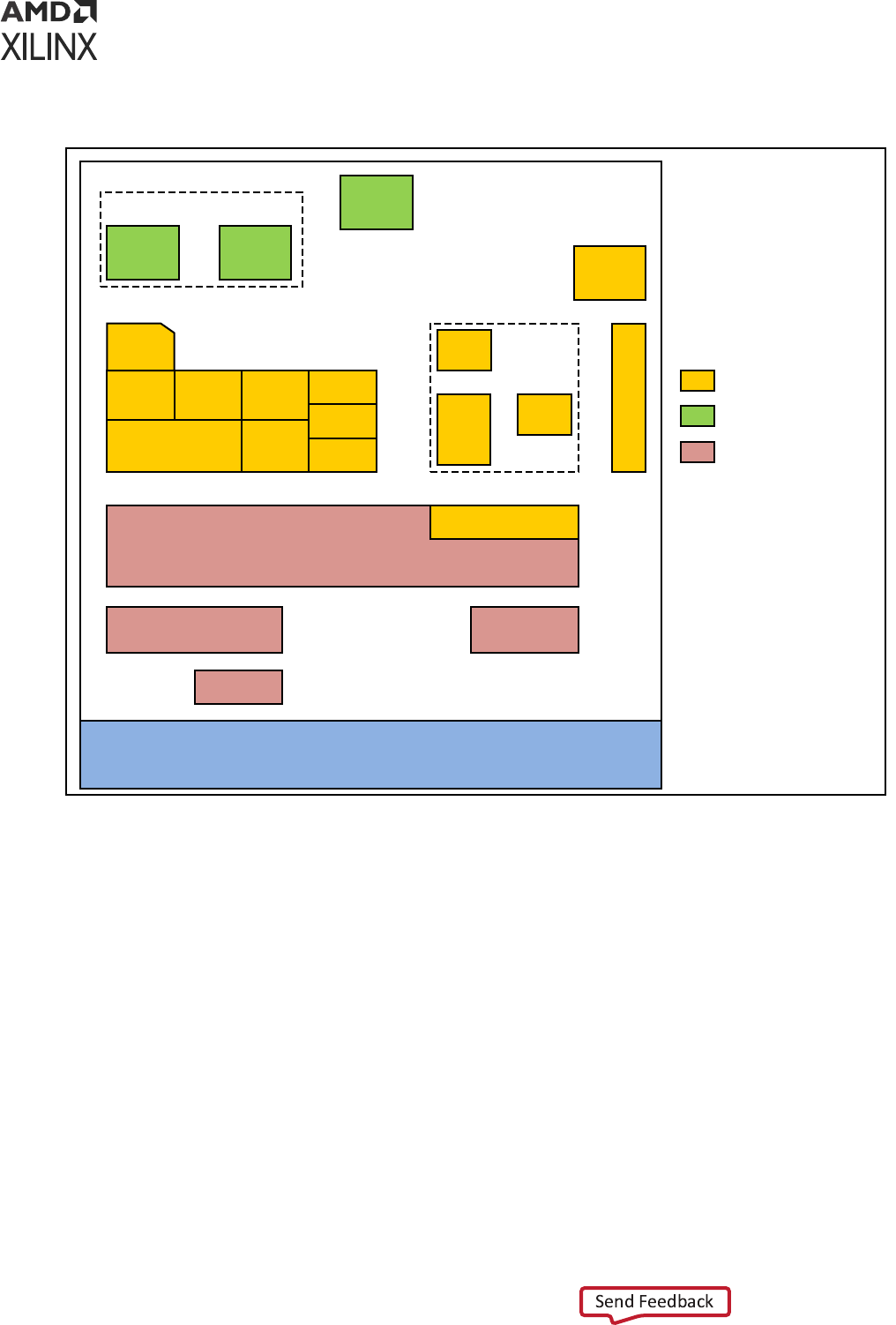
Figure 41: Platform Management at the PS Level
SoC Debug
Quadcore APU
L2
RAM
GPU
Interconnect IPI
IOU CSU PMU
eFuse
AMS
BBRAM RTC
ADMA
SLCR
PLLs
Dual
R5
TCM
GIC
RPU
O
C
M
USB
OSC
PS
PL
DAP, RPU Debug
BPU
Low power domain
Battery power domain
Full power domain
X19226-071317
From the power perspecve, Zynq UltraScale+ MPSoCs oers the following modes of operaon
at the PS level:
• Full-power operaon mode
• Low-power operaon mode
• Deep-sleep mode
• Shutdown mode
• Baery-power mode
The following secons describe these modes.
Chapter 9: Platform Management
UG1137 (v2022.2) November 2, 2022 www.xilinx.com
Zynq UltraScale+ MPSoC: Software Developers Guide 122

Full-Power Operation Mode
In the full-power operaon mode (shown as full power domain in the gure above), the enre
system is up and running. Total power dissipaon depends on the number of components that
are running: their states and their frequencies. In this mode, dynamic power will likely dominate
the total power dissipaon.
To opmize stac and dynamic power in full-power mode, all large modules have their own
power islands to allow them to be shut down when they are not being used. To understand about
full-power operaon mode, see this link to the “Plaorm Management Unit” chapter in the Zynq
UltraScale+ Device Technical Reference Manual (UG1085).
Low-Power Operation Mode
In the low-power operaon mode, a subset of the PS (shown as low-power domain in the gure
above) is powered up that includes: the PMU, RPU, CSU, and the IOU.
In this mode, the ability to change system frequency allows power dissipaon to be tuned. The
CSU must be running connuously to monitor the system security against SEU and tampering. In
this mode, the ability to change system frequency allows power dissipaon to be tuned.
The low-power mode includes all lower-domain peripherals. Among the blocks within the low-
power mode, PLLs, dual Cortex-R5F, USBs, and the TCM and OCM block RAMs oer power
gang.
Note: SATA, PCIe
®
, and DisplayPort blocks are within the full power domain (FPD).
You can control power gang to dierent blocks through soware by conguring the LPD_SLCR
registers. See the SLCR_Registers link in the Zynq UltraScale+ Device Register Reference (UG1087)
for more informaon on LPD_SLCR register.
Deep-Sleep Operation Mode
Deep-Sleep is a special mode in which the PS is suspended and waing a wake-up signal. The
wake can be triggered by the MIO, the USB, or the RTC.
Upon wake, the PS does not have to go through the boot process, and the security state of the
system is preserved. The device consumes the lowest power during this mode while sll
maintaining its boot and security state.
In this mode, all the blocks outside the low-power domain, such as the system monitor and PLLs,
are powered down. In LPD, Cortex-R5F is powered down. Because this mode has to preserve the
context, TCM and OCM are in a retenon state.
Chapter 9: Platform Management
UG1137 (v2022.2) November 2, 2022 www.xilinx.com
Zynq UltraScale+ MPSoC: Software Developers Guide 123

Shutdown Mode
Shutdown mode powers down the enre APU core. This mode is applicable to APU only. During
shutdown, the enre processor state, including its caches, is completely lost; therefore, soware
is required to save all states before requesng the PMU to power down the APU core.
When a CPU is shutdown, it is expected that any interrupt from a peripheral that is associated
with that CPU to iniate its power up; therefore, the interrupt lines to an APU core are also
routed to the PMU interrupt controller, and are enabled when the APU core is powered down.
The Embedded Energy Management Interface EEMI API Reference Guide (UG1200) describe the
APIs to invoke shutdown.
For more details, see this link to the “Plaorm Management Unit Programming Model” secon in
the Zynq UltraScale+ Device Technical Reference Manual (UG1085).
Battery-Powered Mode
When the system is OFF, limited funconality within the PS must stay ON by operang on a
baery. The following features operate within the baery-powered domain PS:
• Baery-backed RAM (BBRAM) to hold key for secure conguraon
• Real-me clock (RTC) including the crystal I/O
The Zynq UltraScale+ MPSoC includes only one baery-powered domain and only the funcons
those are implemented in the PS can be baery backed-up. The required I/O for the baery-
powered domain includes the baery power pads and the I/O pads for the RTC crystal.
Power Management Framework
The Embedded Energy Management Interface EEMI API Reference Guide (UG1200) describes how to
use the power API funcons.
Note: There is no dierence between bare metal, FreeRTOS, or Linux-specic power management Xilinx
EEMI API oerings.
Wake Up Mechanisms
To understand about wake up mechanisms, see this link to the “Plaorm Management Unit
Operaon” secon of “Chapter 6, Plaorm Management Unit” of theZynq UltraScale+ Device
Technical Reference Manual (UG1085).
Chapter 9: Platform Management
UG1137 (v2022.2) November 2, 2022 www.xilinx.com
Zynq UltraScale+ MPSoC: Software Developers Guide 124

Platform Management for Memory
The Zynq UltraScale+ MPSoCs include large RAMs like L2 cache, OCM, and TCM. These RAMs
support various power management features such as: clock gang, power gang, and memory
retenon modes.
• TCM and OCM support independent power gang and retenon modes.
• The L2 cache controller supports dynamic clock gang, retenon, and shutdown modes to
reduce power consumpon at a ner granularity.
DDR Controller
The DDR controller implements the following mechanisms to reduce its power consumpon:
• Clock Stop: When enabled, the DDR PHY can stop the clocks to the DRAM.
• For DDR2 and DDR3, this feature is only eecve in self-refresh mode.
• For LPDDR2, this feature becomes eecve during idle periods, power-down mode, self-
refresh mode, and deep power-down mode.
• Pre-Charge Power Down: When enabled, the DDRC dynamically uses pre-charge power
down mode to reduce power consumpon during idle periods. Normal operaon connues
when a new request is received by the controller.
• Self-Refresh: The DDR controller can dynamically put the DRAM into self-refresh mode
during idle periods. Normal operaon connues when a new request is received by the
controller.
In this mode, DRAM contents are maintained even when the DDRC core logic is fully powered
down; this allows stopping the DDR3X clock and the DCI clock that controls the DDR
terminaon.
Platform Management for Interconnects
The Interconnect lays across mulple power rails and power islands which can be on or o at
dierent mes. To ease the implementaon, in most cases, the clocks for two power domains
that communicate with one another must be asynchronous; consequently, requiring
synchronizers on their interconnecon.
Chapter 9: Platform Management
UG1137 (v2022.2) November 2, 2022 www.xilinx.com
Zynq UltraScale+ MPSoC: Software Developers Guide 125

To ease ming, the power domain is placed exactly at the clock crossing. The synchronizer must
be implemented as two separate pieces with each placed in one of the two domains that are
connected through the synchronizer, creang a bridge.
The bridge consists of a slave interface and a master interface with each lying enrely within a
single power and clock domain. The clock frequencies at the interfaces can vary independent of
each other, and each half can be reset independent of the other half.
Level shiers or clamping, or both, must be implemented between the two halves of the bridge
for mul-voltage implementaon or power-o.
Also, the bridge keeps track of open transacons, as follows:
• When the bridge receives a power-down request from the PMU, it logs that request.
• All new transacons return an error while the previously open transacons are being
processed as usual unl the transacon counter becomes 0. At that point, the bridge
acknowledges to the PMU that it is safe to shut down the master or slave connected to the
bridge.
• The enre Interconnect shuts down only when all bridges within that interconnect are idle.
For more details, see this link to the “PMU Interconnect” sub-secon in the “Plaorm
Management Unit” chapter of the Zynq UltraScale+ Device Technical Reference Manual (UG1085).
PMU Firmware
Every system conguraon that is supported by Xilinx includes PMU rmware in addion to the
funcons of power-up and sleep management. The PMU can execute user programs that
implement advanced system monitoring and power management algorithms. In this mode, an
applicaon or a real-me processor copies the power management program into the PMU
internal RAM through an inbound LPD switch. The PMU executes soware that implements the
required reset, power management, system monitoring, and interrupt controls within all Xilinx
supported system conguraons.
For more details, see this link to the “Plaorm Management Unit Programming Model” secon in
“Chapter 6” of the Zynq UltraScale+ Device Technical Reference Manual (UG1085).
You can use the Vis soware plaorm to create custom PMU rmware. It provides the source
code for the PMU rmware template and the necessary library support. For details on how to
create a Vis project, see Chapter 5: Soware Development Flow.
Chapter 9: Platform Management
UG1137 (v2022.2) November 2, 2022 www.xilinx.com
Zynq UltraScale+ MPSoC: Software Developers Guide 126

Chapter 10
Platform Management Unit
Firmware
The Plaorm Management Unit (PMU) in Zynq
®
UltraScale+™ MPSoCs is located within the
Low-power sub-system. The PMU consists of a MicroBlaze™ processor which loads executable
code from 32 KB ROM and 128 KB RAM into at memory space. The PMU controls the power-
up, reset, and monitoring of resources within the system including inter-processor interrupts and
power management registers. The ROM is preloaded with PMU bootROM (PBR) which performs
pre-boot tasks and enters a service mode. PMU_FW must be loaded to provide advanced system
funconality for each of the Xilinx
®
supported use-cases. This chapter explains the features and
funconality of PMU rmware developed for Zynq UltraScale+ MPSoC.
Features
The following are the key features of PMU rmware:
• Provides modular funconality: PMU rmware is designed to be modular. It enables you to
add a new funconality in the form of a module
• Provides easy customizaon of modules
• Easily congurable to include only the required funconality for a user applicaon
• Support communicaon with other components in the system over IPI (Inter-Processor
Interrupt)
• Run me congurability for EM module
• Support for various Power Management features
Chapter 10: Platform Management Unit Firmware
UG1137 (v2022.2) November 2, 2022 www.xilinx.com
Zynq UltraScale+ MPSoC: Software Developers Guide 127

PMU Firmware Architecture
The following gure shows the architecture block diagram of PMU rmware. PMU rmware is
designed to be modular and enables adding new funconality in the form of modules. Each
funconally disnct feature is designed as a module so that the PMU rmware can be congured
to include only the required funconality for a user applicaon. This type of modular design
allows easy addion of new features and opmizes memory footprint by disabling unused
modules.
PMU rmware can be divided into base rmware and modules. PMU Base Firmware does
inializaon of modules, registering events for the modules, and provides all the common
funcons that may be required by the modules. These common funcons can be categorized into
the following APIs:
1. PMU rmware Core APIs
a. Scheduler
b. Event Manager
c. IPI Manager
2. PMU rmware General APIs
a. BSP/Ulity APIs
b. Reset Services APIs
c. ROM Services APIs
These APIs can be used by the modules in PMU rmware to perform the specied acons as
required.
Chapter 10: Platform Management Unit Firmware
UG1137 (v2022.2) November 2, 2022 www.xilinx.com
Zynq UltraScale+ MPSoC: Software Developers Guide 128

Figure 42: PMU firmware Architecture Block diagram
Execution Flow
The inializaon in PMU rmware takes place in a normal context. Interrupts are disabled to
avoid unintended interrupons and prevent usage of the system resources before they are
properly inialized. Aer inializaon completes, interrupts are enabled and the required tasks
are scheduled to be executed. The system enters in to a sleep state. The system wakes up only
when an event occurs or the scheduled tasks are triggered and the corresponding handlers are
executed. The following gure shows the state transions for PMU rmware.
Chapter 10: Platform Management Unit Firmware
UG1137 (v2022.2) November 2, 2022 www.xilinx.com
Zynq UltraScale+ MPSoC: Software Developers Guide 129

Figure 43: State Transitions for PMU firmware in Main Loop
Main Loop
[Active]
Execute Triggered
Tasks
[Active]
Execute Interrupt
Handlers
Wake on Interrupt
Other Wakes
[Sleep]
Main Loop
[Active]
Execute Triggered
Tasks
[Active]
Execute Interrupt
Handlers
[Sleep]
X24857-120120
PMU rmware execuon ow consists of the following three phases:
• Inializaon phase: This phase consists of PMU rmware starng up, performing self-tests
and validaons, inializing the hardware, creang and inializing modules. Interrupts are
disabled during this phase and are enabled at the end.
• Post inializaon: In this phase, PMU rmware enters service mode, wherein it enters into
sleep and waits for an interrupt.
• Waking up: PMU rmware enters the interrupt context and services the interrupt. Aer
compleng this task, it goes back to sleep.
The following gure shows the execuon ow for PMU rmware.
Chapter 10: Platform Management Unit Firmware
UG1137 (v2022.2) November 2, 2022 www.xilinx.com
Zynq UltraScale+ MPSoC: Software Developers Guide 130

Figure 44: Execution Context View for PMU firmware
Interrupt ContextMain Loop
Start Up
Create Modules
Initialize Modules
Enable Interrupts
Sleep
Execute Triggered
Tasks
Interrupt
Handler
-Dispatch Events to registered
modules
-Modules execute the handlers
-Dispatch IPI to registered
modules
-Modules execute IPI handlers
PIT:
-Flag tasks for execution
interrupt
reti
interrupt
reti
X24856-120120
Handling Inter-Process Interrupts in PMU
firmware
IPI is a key interface between PMU rmware and non-PMU enes on the SoC. PMU includes
four Inter-Processor Interrupts (IPI) assigned to it and one set of buers. PMU rmware uses
IPI-0 and associated buers for communicaon by default, which is iniated by other masters on
SoC to PMU. PMU rmware uses IPI-1 and associated buers for callbacks from PMU to other
masters and for communicaon iniated by PMU rmware.
The following gure shows the IPI handling stack with interfaces between dierent components
involved in this process. PMU rmware uses IPI driver to send and receive the messages. An IPI
manager layer in Base Firmware is implemented over the driver and it takes care of dispatching
the IPI message to the registered module handlers based on IPI ID in the rst word of the
message. The following table displays the message format for IPI.
Table 32:
IPI Message Format
Word Content Description
0 Header <target_module_id, api_id>
Chapter 10: Platform Management Unit Firmware
UG1137 (v2022.2) November 2, 2022 www.xilinx.com
Zynq UltraScale+ MPSoC: Software Developers Guide 131

Table 32: IPI Message Format (cont'd)
Word Content Description
1 Payload Module dependent payload
2
3
4
5
6 Reserved Reserved - for future use
7 Checksum
IPI-1 is used for the callbacks from PMU to other masters and for communicaon iniated by
PMU rmware. Currently, PM and EM modules use IPIs and this can be taken as reference for
implemenng custom modules which require IPI messaging.
Figure 45: IPI Handler Stack with Interfaces
Core Framework
IPI Manager
IPI Driver
Module
GetSource
Write Buffer
TriggerIPI
Read Buffer
GetIpiMask
GetMsg
SendMsg
Dispatch IPI
X22155-121818
PMU rmware provides wrapper APIs around IPI driver funcons to send and receive IPI
messages. During inializaon, PMU rmware inializes the IPI driver and enables IPI interrupt
from the masters which are IPI assigned.
Send IPI Message
XPfw_IpiWriteMessage() API is used to send IPI message to target. This funcon internally
calls the IPI driver write API with buer type as Message buer.
Chapter 10: Platform Management Unit Firmware
UG1137 (v2022.2) November 2, 2022 www.xilinx.com
Zynq UltraScale+ MPSoC: Software Developers Guide 132

Parameters
Table 33: Send IPI Message
Parameter Description
ModPtr Module pointer from where the IPI message is being sent. In IPI
message, target_module_id field will be updated with the Module IPI ID
information which is present in Module pointer.
DestCpuMask Destination target IPI ID
MsgPtr Message Pointer
MsgLen Message Length
Return
XST_SUCCESS: If message is sent successfully.
XST_FAILURE: If message fails.
Send IPI Response
XPfw_IpiWriteResponse() API is used to send the response to the master which sent an IPI
message. This funcon internally calls the IPI driver write API with buer type as Response
buer.
Parameters
Table 34: Send IPI Response
Parameter Description
ModPtr Module pointer to check which module received this IPI response
SrcCpuMask Source IPI ID to read IPI response
MsgPtr Response Message Pointer
MsgLen Response Message Length
Return
XST_SUCCESS: If IPI response is read successfully.
XST_FAILURE: If response fails.
Read IPI Message
XPfw_IpiReadMessage() is used to read the IPI message received when IPI interrupt comes.
This funcon internally calls the IPI driver read API with buer type as Message buer.
Chapter 10: Platform Management Unit Firmware
UG1137 (v2022.2) November 2, 2022 www.xilinx.com
Zynq UltraScale+ MPSoC: Software Developers Guide 133

Parameters
Table 35: Read IPI Message
Parameter Description
SrcCpuMask Source IPI ID to read the IPI message
MsgPtr Message Pointer
MsgLen Message Length
Return
XST_SUCCESS: If IPI message is read successfully.
XST_FAILURE: If message fails.
Read IPI Response
XPfw_IpiReadResponse() is used to read the IPI response for the message sent. This
funcon internally calls the IPI driver read API with buer type as response buer.
Parameters
Table 36: Read IPI Response
Parameter Description
ModPtr Module pointer to check which module received this IPI response
SrcCpuMask Source IPI ID to read IPI response
MsgPtr Response Message Pointer
MsgLen Response Message Length
Return
XST_SUCCESS: If IPI response is read successfully.
XST_FAILURE: If response fails.
Triggering an IPI
XPfw_IpiTrigger() is used to trigger an IPI to the desnaon. This funcon internally calls
the IPI driver trigger. This funcon should be called aer the IPI message writes IPI buer.
Chapter 10: Platform Management Unit Firmware
UG1137 (v2022.2) November 2, 2022 www.xilinx.com
Zynq UltraScale+ MPSoC: Software Developers Guide 134

Parameters
Table 37: Triggering an IPI
Parameter Description
DestCpuMask Destination target IPI ID
Return
XST_SUCCESS: If IPI is triggered successfully.
XST_FAILURE: If trigger fails.
Note: Vivado
®
allows you to enable or disable the IPI. To do so, select MPSoC IP → Re-customize IP →
Switch To Advanced Mode → Advanced Conguraon → Inter Processor Interrupt (IPI) Conguraon →
IPI-Master Mapping. However, it is not recommended that you disable IPI channels for APU or RPU for the
PMU rmware PM module to work as expected because in the default conguraon, PM assumes that
both APU and RPU IPI channels are enabled.
PMU Firmware Modules
PMU rmware consists of the following modules:
1. Error Management (EM)
2. Power Management (PM)
3. Scheduler
4. Safety Test Library (STL)
PMU rmware has a module data structure (XPfw_Module_t) which contains the informaon
about the module. This data structure is dened for each module when the module is created.
The following table shows its members.
Table 38: Module Data Structure Members
Member Range Additional Information
ModId 0.. 31
CfgInitHandler Init handler function pointer Default to NULL
IpiHandler Handler for IPI manager Default to NULL
EventHandler Handler for registered events of the
module
Default to NULL
IpiId 16-bit IPI ID Unique to each module
Chapter 10: Platform Management Unit Firmware
UG1137 (v2022.2) November 2, 2022 www.xilinx.com
Zynq UltraScale+ MPSoC: Software Developers Guide 135

PMU rmware also has a core data structure which contains the list and the details of all
modules. The following table shows its members.
Table 39: Core Data Structure Members
Member Range Additional Information
ModList array 0.. 31 Module list array (of 32 elements) of
Module structure
Scheduler Scheduler structure Scheduler task owned by the module
ModCount 0.. 31
IsReady Core is ready/dead
Mode Safety Diagnostics mode/Normal mode
Base PMU rmware supports a few APIs that are used by these modules. Also, if you want to
create a custom module, these APIs can be used from xpfw_core.h.
Creating a Module
XPfw_CoreCreateMod() API is called during the startup to create a module. PMU rmware
can have maximum of 32 modules. This funcon checks if the module count reached the
maximum count. If not, it lls in the details to core structure ModList and returns this module
data structure to the caller. Otherwise, it returns NULL.
Setting up Handlers for the Module
Each module can be provided with three handlers which are called during the respecve phases
as described below:
Table 40: Module Handlers
Module
Handler
Purpose API for Registering the Handler
Execution
context
Init Called during the init of the core to
configure the module, register for
events or add scheduler tasks. This
can be used to load the
configuration data into the module
if required.
XPfw_CoreSetCfgHandler(const XPfw_Module_t
*ModPtr,
XPfwModCfgInitHandler_tCfgHandler);
StartUp
Event Handler Called when an event occurs
(module should have registered for
this event, preferably during the init
phase
XPfw_CoreSetEventHandler(const
XPfw_Module_t *ModPtr,
XPfwModEventHandler_t EventHandler);
Interrupt
IPI Handler Called when an IPI message with
respective module-id arrives
XPfw_CoreSetIpiHandler(const XPfw_Module_t
*ModPtr, XPfwModIpiHandler_t IpiHandler,
u16 IpiId);
Interrupt
Chapter 10: Platform Management Unit Firmware
UG1137 (v2022.2) November 2, 2022 www.xilinx.com
Zynq UltraScale+ MPSoC: Software Developers Guide 136

PMU Firmware Build Flags
In PMU rmware, each module can be enabled/disabled based on your requirement. This is
achieved by using build ags. The following table describes the important build ags in PMU
rmware and its usage. Please see xpfw_config.h le in PMU rmware sources for a complete
list of build ags.
Table 41: PMU Firmware Build Flags
Flag Description Prerequisites
Default
Setting
XPFW_DEBUG_DETAILED Enables detailed debug prints in PMU
firmware.
This feature is supported in 2017.3 release
and above.
Disabled
PM_LOG_LEVEL Enables print based debug functions for
PM module. Possible values are:
• Alerts
• Errors
• Warnings
• Information
Higher numbers include the debug scope
of lower number, i.e. enabling 3
(warnings) also enables 1 (alerts) and 2
(errors).
Disabled
ENABLE_EM Enables Error Management Module. ENABLE_SCHEDULER Disabled
ENABLE_ESCALATION Enables escalation of sub-system restart to
SRST/PS-Only if the first restart attempt
fails.
ENABLE_RECOVERY,
ENABLE_EM,
ENABLE_SCHEDULER
Disabled
ENABLE_RECOVERY Enables WDT based restart of APU sub-
system.
ENABLE_EM, ENABLE_PM,
EMABLE_SCHEDULER
Disabled
ENABLE_PM Enables Power Management Module Enabled
ENABLE_NODE_IDLING Enables idling and reset of nodes before
force shutdown of a sub-system.
Disabled
ENABLE_SCHEDULER Enables Scheduler module Enabled
ENABLE_WDT Enables CSU WDT based restart of system
used by PMU.
ENABLE_SCHEDULER,
ENABLE_EM
Disabled
ENABLE_STL Enables STL Module. None Disabled
ENABLE_RTC_TEST Enables RTC event handler test module. None Disabled
ENABLE_SAFETY Enables CRC calculation for IPI messages. None Disabled
ENABLE_FPGA_LOAD Enables FPGA bit stream loading feature. ENABLE PM Enabled
ENABLE_SECURE Enables security features. ENABLE PM Enabled
IDLE_PERIPHERALS Enables idling peripherals before PS-only
or System reset.
ENABLE PM Disabled
ENABLE_POS Enables Power Off Suspend feature. ENABLE PM Disabled
EFUSE_ACCESS Enables efuse access feature. ENABLE PM Disabled
ENABLE_UNUSED_RPU_
PWR_DWN
Powers down RPU(s) and slaves if they are
not running after receiving PmInitFinalize.
Enabled
Chapter 10: Platform Management Unit Firmware
UG1137 (v2022.2) November 2, 2022 www.xilinx.com
Zynq UltraScale+ MPSoC: Software Developers Guide 137

Table 41: PMU Firmware Build Flags (cont'd)
Flag Description Prerequisites
Default
Setting
USE_DDR_FOR_APU_RESTART Enables handling of APU restart gracefully
by storing FSBL to DDR during boot and
restoring it back to OCM before
performing APU restart.
ENABLE_SECURE Enabled
Error Management (EM) Module
Error Management Hardware
Zynq UltraScale+ MPSoC has a dedicated error handler to aggregate and handle fatal errors
across the SoC. See the TRM/Arch Spec for more informaon.
All fatal errors routed to Error Manager can either set to be handled by HW (and trigger a
SRST/PoR/PS error out) or trigger an interrupt to PMU.
Error Management in PMU firmware
Error management module inializes and handles the errors that are generated by hardware and
provides an opon for you to customize these handlers. In hardware, there are two error status
registers which hold the type of error that occurred. Also any error can be enabled/disabled from
interrupng the PMU MicroBlaze. For each of the errors, you can decide what acon should be
taken when the error occurs. The possible scenarios would be one or a combinaon of the
following choices:
1. Asserng of PS_ERROR_OUT signal on the device
2. Generaon of an interrupt to the PMU processor
3. Generaon of a system reset (SRST)
4. Generaon of a power-on-reset (POR)
PMU rmware provides APIs to register custom error handlers or assign a default (SRST/PoR/PS
error out) acon in response to an Error. When PMU rmware starts, it sets an error acon as
interrupt to PMU for some of the errors and PS error out for others as per the ErrorTable[]
structure dened in xpfw_error_manager.c.
Error Management API Calls
This secon describes the APIs supported by Error Management module in PMU rmware.
Chapter 10: Platform Management Unit Firmware
UG1137 (v2022.2) November 2, 2022 www.xilinx.com
Zynq UltraScale+ MPSoC: Software Developers Guide 138
Setting up Error Action
XPfw_EmSetAction() API is used to setup an acon for the specied error.
Parameters
Table 42: XPfw_EmSetAction
Parameter Description
ErrorId ErrorId is ID for error as defined in EM Error ID Table.
ActionId ActionId is one of the actions defined in EM Error Action
Table.
ErrorHandler ErrorHandler is the handler to be called in case where action
is interrupt to PMU
Return
XST_SUCCESS: If error acon is set properly.
XST_FAILURE: If error acon fails.
Removing Error Action
XPfw_EmDisable() API is used to remove error acon for the specied error.
Parameters
Table 43: XPfw_EmDisable
Parameter Description
ErrorId ErrorId is ID for error to remove error action
Return
XST_SUCCESS: If successful.
XST_FAILURE: If acon fails.
Processing an Error
XPfw_EmProcessError() API processes the errors that occur. If the respecve error is
registered with an error handler, then this funcon will call the respecve handler to take
appropriate acon.
Chapter 10: Platform Management Unit Firmware
UG1137 (v2022.2) November 2, 2022 www.xilinx.com
Zynq UltraScale+ MPSoC: Software Developers Guide 139
Parameters
Table 44: XPfw_EmProcessError
Parameter Description
ErrorType Type of error received
(EM_ERR_TYPE_1: For errors in PMU GLOBAL
ERROR_STATUS_1
EM_ERR_TYPE_2: For errors in PMU GLOBAL
ERROR_STATUS_2)
Return
XST_SUCCESS: If successful.
XST_FAILURE: If acon fails.
IPI Handling by EM Module
Along with the PM module, error management module also uses IPI-0 channel for message
exchange. APU and RPU 0/1 masters can communicate to this module using IPI. The
target_module_id in IPI message dierenates which module needs to take an acon based
on the message received. The target_module_id for IPI handler registered for EM module is
0xE. Currently, PMU rmware supports only the messages shown in the following table using IPI.
Table 45: IPI Messages Supported by PMU firmware
S.No IPI Message IPI Message ID/API ID
1 Set error action 0x1
2 Remove error action 0x2
3 Send errors occurred 0x3
Set Error Action
When this IPI message is received from any target to PMU rmware, PMU rmware sets the
error acon for the error ID received in the message. If processing of the message is successful, it
sends SUCCESS (0x0) response to the target. Otherwise FAILURE (0x1) response will be sent.
The message format for the same is as below:
Table 46: Message Format for Error Action
Word Description
0 <target_module_id, api_id>
1 Error ID. See EM Error ID Table for the Error IDs supported.
2 Error Action. See EM Error Action Table for the Error Actions supported.
Chapter 10: Platform Management Unit Firmware
UG1137 (v2022.2) November 2, 2022 www.xilinx.com
Zynq UltraScale+ MPSoC: Software Developers Guide 140

Remove Error Action
When this IPI message is received from any target to PMU rmware, EM module IPI handler will
remove the error acon for the error ID received. And aer processing the message, it will send
SUCCESS/FAILURE response to the target respecvely. The message format for the same is as
below:
Table 47: Message Format for Removing Error Action
Word Description
0 <target_module_id, api_id>
1 Error ID. See EM Error ID Table for the Error IDs supported.
Send Errors Occurred
PMU rmware saves the errors that occur in the system and sends to the target upon request.
The message format is as below:
Table 48: Message Format for Sending Errors Occurred
Word Description
0 <target_module_id, api_id>
The following table shows the response message sent by PMU rmware.
Table 49: Response Message by PMU Firmware
Word Description
0 <target_module_id, Success/Failure>
1 Error_1 (Bit description is as ERROR_STATUS_1 register in PMU Global registers. If a bit is
set to 1, then it means the respective error as described in ERROR_STATUS_1 has
occurred)
2 Error_2 (Bit description is as ERROR_STATUS_2 register in PMU Global registers. If a bit is
set to 1, then it means the respective error as described in ERROR_STATUS_2 has
occurred)
3 PMU RAM Correctable ECC Count
EM Error ID Table
Table 50: EM Error ID Table
Error ID
Error
Number
Error Description
Default Error
Action
EM_ERR_ID_CSU_ROM 1 Errors logged by CSU bootROM (CBR) PS Error Out
EM_ERR_ID_PMU_PB 2 Errors logged by PMU bootROM (PBR)
in the pre-boot stage
PS Error Out
Chapter 10: Platform Management Unit Firmware
UG1137 (v2022.2) November 2, 2022 www.xilinx.com
Zynq UltraScale+ MPSoC: Software Developers Guide 141

Table 50: EM Error ID Table (cont'd)
Error ID
Error
Number
Error Description
Default Error
Action
EM_ERR_ID_PMU_SERVICE 3 Errors logged by PBR in service mode PS Error Out
EM_ERR_ID_PMU_FW 4 Errors logged by PMU firmware PS Error Out
EM_ERR_ID_PMU_UC 5 Un-Correctable errors logged by PMU
HW. This includes PMU ROM validation
Error, PMU TMR Error, uncorrectable
PMU RAM ECC Error, and PMU Local
Register Address Error
PS Error Out
EM_ERR_ID_CSU 6 CSU HW related Errors PS Error Out
EM_ERR_ID_PLL_LOCK 7 Errors set when a PLL looses lock (These
need to be enabled only after the PLL
locks-up)
PS Error Out
EM_ERR_ID_PL 8 PL Generic Errors passed to PS PS Error Out
EM_ERR_ID_TO 9 All Time-out Errors [FPS_TO, LPS_TO] PS Error Out
EM_ERR_ID_AUX3 10 Auxiliary Error 3 PS Error Out
EM_ERR_ID_AUX2 11 Auxiliary Error 2 PS Error Out
EM_ERR_ID_AUX1 12 Auxiliary Error 1 PS Error Out
EM_ERR_ID_AUX0 13 Auxiliary Error 0 PS Error Out
EM_ERR_ID_DFT 14 CSU System Watch-Dog Timer Error System Reset
EM_ERR_ID_CLK_MON 15 Clock Monitor Error PS Error Out
EM_ERR_ID_XMPU 16 XPMU Errors [LPS XMPU, FPS XPMU] Interrupt to PMU
EM_ERR_ID_PWR_SUPPLY 17 Supply Detection Failure Errors PS Error Out
EM_ERR_ID_FPD_SWDT 18 FPD System Watch-Dog Timer Error Interrupt to PMU if
ENABLE_RECO
VERY flag is defined
and FSBL runs on APU.
Otherwise, System
Reset
EM_ERR_ID_LPD_SWDT
19 LPD System Watch-Dog Timer Error Interrupt to PMU if
ENABLE_RECO
VERY flag is defined
and FSBL runs on RPU.
Otherwise, System
Reset
EM_ERR_ID_RPU_CCF
20 Asserted if any of the RPU CCF errors
are generated
PS Error Out
EM_ERR_ID_RPU_LS 21 Asserted if any of the RPU CCF errors
are generated
Interrupt to PMU
EM_ERR_ID_FPD_TEMP 22 FPD Temperature Shutdown Alert PS Error Out
EM_ERR_ID_LPD_TEMP 23 LPD Temperature Shutdown Alert PS Error Out
EM_ERR_ID_RPU1 24 RPU1 Error including both Correctable
and Uncorrectable Errors
PS Error Out
EM_ERR_ID_RPU0 25 RPU0 Error including both Correctable
and Uncorrectable Errors
PS Error Out
EM_ERR_ID_OCM_ECC 26 OCM Uncorrectable ECC Error PS Error Out
EM_ERR_ID_DDR_ECC 27 DDR Uncorrectable ECC Error PS Error Out
Chapter 10: Platform Management Unit Firmware
UG1137 (v2022.2) November 2, 2022 www.xilinx.com
Zynq UltraScale+ MPSoC: Software Developers Guide 142

EM Error Action Table
Table 51: EM Error Action Table
Error Action
Error Action
Number
Error Action Description
EM_ACTION_POR 1 Trigger a Power-On-Reset
EM_ACTION_SRST 2 Trigger a System Reset
EM_ACTION_CUSTOM 3 Call the custom handler registered as ErrorHandler
parameter
EM_ACTION_PSERR 4 Trigger a PS-Error Out action
PMU Firmware Signals PLL Lock Errors on
PS_ERROR_OUT
When EM module is enabled, it is recommended to enable SCHEDULER also. During FSBL
execuon of psu_init, it is expected to get the PLL lock errors. To avoid these errors during
EM module inializaon, PMU rmware will not enable PLL Lock errors. It waits for psu_init
compleon by FSBL using a scheduler task. Aer FSBL completes execuon of psu_init, PMU
rmware will enable all PLL Lock errors.
In xpfw_error_management.c, you can see the following default behavior of the PMU
rmware for PLL Lock Errors:
[EM_ERR_ID_PLL_LOCK] = { .Type = EM_ERR_TYPE_2, .RegMask =
PMU_GLOBAL_ERROR_STATUS_2_PLL_LOCK_MASK, .Action = EM_ACTION_NONE, .Handler
=
NullHandler},
where, PMU_GLOBAL_ERROR_STATUS_2_PLL_LOCK_MASK is #dened with 0X00001F00
value, which means that all the PLL Lock Errors are enabled. Hence, if the design do not use any
PLL/PLLs that are not locked, this triggers the PS_ERROR_OUT signal. It means that the
PMU_GLOBAL.ERROR_STATUS_2 register (bits [12:8]) signals that one or more PLLs are NOT
locked and that triggers the PS_ERROR_OUT signal.
To analyze further and see if this is really an issue is to fully understand the status of the PLL in
the design. For example, if the design only uses IO_PLL and DDR_PLL and
PMU_GLOBAL.ERROR_STATUS_2 register signals 0x1600 value, it means that the RPU_PLL,
APU_PLL, and Video_PLL Lock errors have occurred. Looking at a few more registers, you can
really understand the status of the PLLs.
PLL_STATUS
• PLL_STATUS (CRL_APB) = FF5E0040: 00000019
• PLL_STATUS (CRF_APB) = FD1A0044: 0000003A
Chapter 10: Platform Management Unit Firmware
UG1137 (v2022.2) November 2, 2022 www.xilinx.com
Zynq UltraScale+ MPSoC: Software Developers Guide 143

Table 52: PLL_STATUS
PLL STATUS ERROR_STATUS_2
IOPLL is locked and stable Bit [8] is for IO_PLL = 0
RPLL is stabled and NOT locked (which means bypassed) Bit [9] is for RPU_PLL = 1
APPL is stabled and NOT locked (which means bypassed) Bit [10] is for APU_PLL = 1
DPLL is locked and stable Bit [11] is for DDR_PLL = 0
VPLL is stabled and NOT locked (which means bypassed) Bit [12] is for Video_PLL = 1
Hence, if the design only uses IO_PLL and DDR_PLL, then it is not really an error to have
RPU_PLL, APU_PLL and Video_PLL in NOT locked status.
Xilinx recommends you to customize the PMU_GLOBAL_ERROR_STATUS_2_PLL_LOCK_MASK
to cover only the PLL of interest so that you can have a meaningful PS_ERROR_OUT signal.
Example:
#define PMU_GLOBAL_ERROR_STATUS_2_PLL_LOCK_MASK ((u32)0X00000900U) will only
signal on PS_ERROR_OUT IO_PLL and DDR_PLL errors.
Power Management (PM) Module
Zynq UltraScale+ MPSoC Power Management framework is based on an implementaon of the
Embedded Energy Management Interface (EEMI). This framework allows soware components
running across dierent processing units (PUs) on a chip or device to issue or respond to requests
for power management.
The Power Management module is implemented within the PMU rmware as an event-driven
module. Events processed by the Power Management module are called power management
events. All power management events are triggered via interrupts.
When handling an interrupt the PMU rmware determines whether the associated event shall be
processed by the Power Management module. Accordingly, if the PMU rmware determines that
an event is power management related and if the Power Management module is enabled, the
PMU rmware triggers it to process the event.
For example, all the PS and PL interrupts can be routed to the PMU via the GIC Proxy. When the
applicaon processors (APU or RPU) are temporarily suspended, the PMU handles the GIC Proxy
interrupt and wakes up the applicaon processors to service the original interrupts. The PMU
rmware does not actually service these interrupts, although you are free to customize the PMU
rmware so that these interrupts are serviced by the PMU instead of by the applicaon
processors. For more informaon, see the ‘Interrupts’ chapter of the Zynq UltraScale+ Device
Technical Reference Manual (UG1085).
Chapter 10: Platform Management Unit Firmware
UG1137 (v2022.2) November 2, 2022 www.xilinx.com
Zynq UltraScale+ MPSoC: Software Developers Guide 144

When processing a power management event the Power Management controller may exploit the
PMU ROM handlers for parcular operaons regarding the state control of hardware resources.
Warm restart and FPGA conguraon manager are part of Power Management module. PMU
rmware includes XilFPGA and XilSecure libraries to support the funconalies of PL FPGA
conguraon and to access secure features respecvely. See Chapter 11: Power Management
Framework for more informaon.
Note: Since the Power Management module uses base rmware APIs such as IPI manager/event manager,
it is not possible to run standalone power management features without PMU rmware. See PM Examples
wiki page for XilPM based design examples.
Scheduler
A scheduler is required by modules like STL in order to support periodic tasks like register
coverage, scrubbing, etc. PMU rmware also uses scheduler for LPD WDT funconality. This will
be explained in the following secon. PMU MicroBlaze has 4 PITs (0-3) and Scheduler uses PIT1.
The scheduler supports up to 10 tasks. The following table shows the Scheduler’s task list data
structure with members.
Table 53: Scheduler Data Structure Members
Member Values/Range Additional information
Task ID 0 0.. 9 0 - Highest priority
Interval Task interval in Milliseconds
OwnerId 0.. 9 Modules that owns this task
Status Enabled/Disabled
Callback Function pointer Default to NULL
Note: By default, scheduler funconality is disabled. To enable the same, ENABLE_SCHEDULER build ag
needs to be dened.
Safety Test Library
Safety Test Library (STL) is a collecon of soware safety mechanisms complemenng hardware
safety features for the detecon of random hardware (HW) faults. PMU rmware has a
placeholder for STL inializaon during PMU rmware startup. This is enabled when
ENABLE_STL build ag is dened. The soware library and the safety documentaon can be
seen at the Safety Lounge.
Chapter 10: Platform Management Unit Firmware
UG1137 (v2022.2) November 2, 2022 www.xilinx.com
Zynq UltraScale+ MPSoC: Software Developers Guide 145

CSU/PMU Register Access
The following secon discusses how to Read/Write the CSU and PMU global registers and
provides a list of White and Black registers.
Register Write
$ echo > /sys/firmware/zynqmp/config_reg
Register Read
$ echo > /sys/firmware/zynqmp/config_reg
$ cat /sys/firmware/zynqmp/config_reg
CSU and PMU global registers are categorized into two lists:
• By default, the White list registers can be accessed all the me. The following is a list of white
registers.
○ CSU Module:
- Csu_status
- Csu_mul_boot
- Csu_tamper_trig
- Csu__status
- Jtag_chain_status
- Idcode
- Version
- Csu_rom_digest(0:11)
- Aes_status
- Pcap_status
○ PMU Global Module:
- Global_control
- Global_Gen_Storage0 - 6
- Pers_Glob_Gen_Storage0-6
- Req_Iso_Status
- Req_SwRst_Status
- Csu_Br_Error
Chapter 10: Platform Management Unit Firmware
UG1137 (v2022.2) November 2, 2022 www.xilinx.com
Zynq UltraScale+ MPSoC: Software Developers Guide 146

- Safety_Chk
• The Black list registers can accessed when a compile me ag is set.
Every other register in both the CSU Module and the PMU_GLOBAL Module that is not covered
in the above white list will be a black register. RSA and RSA_CORE module registers are black
registers.
The #define opon (SECURE_ACCESS_VAL) provides access to the black list. To access black
list registers, build the PMU rmware with SECURE_ACCESS_VAL ag set.
Timers
Zynq UltraScale+ MPSoCs have two system watchdog mers, one each for full-power domain
(FPD) and low-power domain (LPD). Each of these WDT provides error condion informaon to
the error manager. EM module can be congured to set a specic error acon when FPD or LPD
WDT expires. This secon describes the usage of these watchdog mers and the PMU rmware
funconality when these watchdog mers expire.
FPD WDT
FPD WDT can be used to reset the APU or the FPD. PMU rmware error management module
can congure the error acon to be taken when the FPD WDT error occurs. PMU rmware
implemented a recovery mechanism for FPD WDT error. This mechanism is disabled by default.
The same can be enabled by dening ENABLE_RECOVERY build ag.
The EM module in PMU rmware sets FPD WDT error acon as ‘system reset’ when recovery
mechanism is not enabled. In this case, PMU rmware doesn't inialize and congure the FPD
WDT. It is le for Linux driver to inialize and start the WDT if required. When WDT expires,
system restart happens.
When ENABLE_RECOVERY ag is dened and FSBL runs on APU, PMU rmware sets FPD WDT
error acon as ‘interrupt to PMU’ and registers a handler to be called when this error occurs. In
this case, when PMU rmware comes up, it inializes and starts the WDT. It also inializes and
sets the mer mode of TTC to interval mode.
PMU rmware congures FPD WDT expiry me to 60 seconds. And if WDT error occurs, PMU
rmware gets an interrupt and it calls the registered handler. PMU rmware has a restart tracker
structure to track the restart phase and other informaon for a master. APU and RPU are the
masters currently using this structure. Following are its members:
Chapter 10: Platform Management Unit Firmware
UG1137 (v2022.2) November 2, 2022 www.xilinx.com
Zynq UltraScale+ MPSoC: Software Developers Guide 147

Table 54: Restart Tracker Structure Members
Member Description
Master Master whose restart cycle is to be tracked
RestartState Track different phases in restart cycle
RestartScope Restart scope upon FPD WDT error interrupt
WdtBaseAddress Base address for WDT assigned to this master
WdtTimeout Timeout value for WDT
ErrorId Error Id corresponding to the WDT
WdtPtr Pointer to WDT for this master
WdtResetId Wdt reset ID
TtcDeviceId TTC timer device ID
TtcPtr Pointer to TTC for this master
TtcTimeout Timeout to notify master for event
TtcResetId Reset line ID for TTC
When WDT error occurs, WDT error handler is called and PMU rmware performs the following:
1. It checks if master is APU and error ID is FPD WDT. Then, it checks if restart state is in
progress or not. If restart state is not in progress, then it changes the restart state to in
progress.
2. Later, it restarts the WDT so that the PMU rmware knows when the WDT error is not due
to APU applicaon.
3. Then, it idles APU by sending an IPI to TF-A through mer interrupt TTC3_0.
Note: This is only true for Linux, and not for bare metal where there is no TF-A.
4. If the rst restart aempt fails, then PMU rmware escalates restart to either system-reset or
PS-only reset if ENABLE_ESCALATION ag is dened. If ENABLE_ESCALATION is not
dened, PMU rmware restarts the APU. Otherwise, PMU rmware performs the following:
• First, PMU rmware checks if PL is congured or not.
• If PL is congured, PMU rmware iniates PS-only restart. Otherwise, it iniates system-
reset.
Note: Ensure that the WDT heartbeat applicaon is running in Linux.
LPD WDT
LPD WDT can be used to reset the RPU. PMU rmware error management module can congure
the error acon to be taken when the LPD WDT error occurs. PMU rmware implements a
recovery mechanism for LPD WDT error. This mechanism is disabled by default. The same can be
enabled by dening the ENABLE_RECOVERY build ag.
Chapter 10: Platform Management Unit Firmware
UG1137 (v2022.2) November 2, 2022 www.xilinx.com
Zynq UltraScale+ MPSoC: Software Developers Guide 148

The EM module in the PMU rmware sets LPD WDT error acon as "system reset' when
recovery mechanism is not enabled. In this case, PMU rmware doesn't inialize and congure
the LPD WDT. It is le to the RPU user applicaon to inialize and start the WDT, if required.
When WDT expires, the system restarts.
When ENABLE_RECOVERY ag is dened and FSBL is running on RPU, PMU rmware sets FPD
WDT error acon as "interrupt to PMU" and registers a handler to be called when this error
occurs. In this case, when PMU rmware comes up, it inializes and starts the WDT.
PMU rmware congures LPD WDT expiry me to 60s. And if WDT error occurs, PMU rmware
gets an interrupt and it calls the registered handler. PMU rmware maintains a restart tracker
structure for LPD WDT. Refer to Table 10-23 for more informaon.
When WDT error occurs, the WDT error handler is called and PMU rmware performs the
following acons:
1. It checks if master is RPU and error ID is LPD WDT. Then, it checks if restart state is in
progress or not. If restart state is not in progress, then it changes the restart state to in
progress and restarts the WDT to track the next WDT expiry.
2. It applies AIB isolaon for RPU and removes it.
3. If restart scope is set as a subsystem, then it will restart RPU subsystem.
4. If restart scope is set as PS only restart, then PMU rmware will restart PS subsystem.
5. If restart scope is set as system, then it will perform the system restart.
CSU WDT
The CSU WDT is congured to be used by PMU rmware that if PMU rmware applicaon
hangs for some reason, then the system would restart. This funconality is enabled only when
ENABLE_WDT ag is dened.
EM modules sets CSU WDT error acon as ‘System Reset’ Inializaon of CSU WDT depends on
bringing WDT out of reset which is performed by psu_init from FSBL. FSBL writes the status
of psu_init compleon to PMU Global general storage register 5, so that PMU rmware can
check for its compleon before inializing CSU WDT. When ENABLE_WDT ag is dened during
PMU rmware inializaon, it adds a task to scheduler to be triggered for every 100 milli-
seconds unl psu_init compleon status is updated by FSBL. Aer psu_init is completed,
this task will be removed from scheduler tasks list and PMU rmware inializes CSU WDT and
congures it to 90 milli-seconds. It also starts a scheduler task to restart the WDT for every 50
milli-seconds. Whenever CSU WDT error occurs due to PMU rmware code hanging, this error is
handled in hardware to trigger ‘System Reset’ and the system will restart.
Following are the dependencies to use this WDT funconality:
1. EM module needs to be enabled by dening ENABLE_EM ag.
Chapter 10: Platform Management Unit Firmware
UG1137 (v2022.2) November 2, 2022 www.xilinx.com
Zynq UltraScale+ MPSoC: Software Developers Guide 149

2. ENABLE_WDT ag needs to be dened to use CSU WDT.
3. Scheduler module needs to be enabled by dening ENABLE_SCHEDULER to add a task to
scheduler to check for psu_init compleon and to restart WDT periodically.
Configuration Object
The conguraon object is a binary data object used to allow updang data structures in the
PMU rmware power management module at boot me. The conguraon object must be
copied into memory by a processing unit on the Zynq UltraScale+ MPSoC. The memory region
containing the conguraon object must be accessible by the PMU.
The PMU is triggered to load the conguraon object via the following API call:
XPm_SetConfiguration(address);
The address argument represents the start address of the memory where the conguraon
object is located. The PMU determines the size of the conguraon object based on its content.
Once the PMU loads the conguraon object it updates its data structures which are used to
manage the states of hardware resources (nodes). Paral conguraons are not possible. If the
conguraon object does not provide informaon as dened in this document or provides paral
informaon, the consistency of PMU rmware power management data cannot be guaranteed.
The creator of the conguraon object must ensure the consistency of the informaon provided
in the conguraon object. The PMU does not change the state of nodes once the conguraon
object is loaded. The PMU also does not check whether the informaon about current states of
nodes provided in the conguraon object really matches the current state of the hardware.
Current state is a state of a hardware resource at the moment of processing the conguraon
object by the PMU.
The conguraon object species the following:
• List of masters available in the system
• All the slave nodes the master is currently using and current requirement of the master for the
slave conguraon
• All the slave nodes the master is allowed to use and default requirement of the master for the
slave conguraon
• For each power node, which masters are allowed to request/release/power down
• For each reset line, which masters are allowed to request the change of a reset line value
• Which shutdown mode the master is allowed to request and shutdown meout value for the
master
Chapter 10: Platform Management Unit Firmware
UG1137 (v2022.2) November 2, 2022 www.xilinx.com
Zynq UltraScale+ MPSoC: Software Developers Guide 150

• Which masters are allowed to set conguraon aer the conguraon is already set upon the
system boot by the FSBL
PM Configuration Object Generation
PM Conguraon Object is generated as follows:
1. Specify the custom PM framework Conguraon using the PCW tool
2. PCW generates the HDF le
3. At build me, the XSA Parser parses the XSA le and insert the conguraon object into the
FSBL code
Figure 46: Configuration Object Generation
PCW HDF Parser FSBL
HDF Config Object
Initial Configuration at Boot
The conguraon object shall be loaded prior to calling any EEMI API, except the following APIs:
• Get API version
• Set conguraon
• Get Chip ID
Unl the rst conguraon object is loaded the PM controller is congured to inially expect the
EEMI API calls from the APU or RPU master, via IPI_APU or IPI_RPU_0 IPI channels, respecvely.
In other words, the rst conguraon object has to be loaded by APU or RPU.
Aer the rst conguraon object is loaded, the next loading of the conguraon object can be
triggered by a privileged master. Privileged masters are dened in the conguraon object that
was loaded the last.
Following are the steps at boot level:
1. FSBL sends the conguraon object to PMU with the Set Conguraon API
2. PMU parses the conguraon object and congures
Chapter 10: Platform Management Unit Firmware
UG1137 (v2022.2) November 2, 2022 www.xilinx.com
Zynq UltraScale+ MPSoC: Software Developers Guide 151

3. PMU powers o all the nodes which are unused aer all the masters have completed the
inializaon
All other requests prior to the rst Set Conguraon API call will be rejected by PMU rmware.
Figure 47: Initial Configuration at Boot
FSBL PMU
PM Init
Set Configuration (ConfigObj)
PMU Firmware Loading Options
PMU rmware can be loaded by either FSBL or CSU BootROM (CBR). Both these ows are
supported by Xilinx. Loading PMU rmware using FSBL has the following benets:
• Possible quick boot me, when PMU rmware is loaded aer bitstream.
• In use cases where you want two BIN les - stable and upgradable, PMU rmware can be part
of the upgradable (by FSBL) image.
IMPORTANT!
CBR loads FSBL. If CBR also loads PMU rmware, it means that the secure headers for
both FSBL and PMU rmware are decrypted with same Key-IV pair, which is a security vulnerability
(security rule is: no two parons should use the same Key-IV pair). This is addressed in FSBL, not in CBR.
Hence, you should avoid CBR loading PMU rmware in secure (decrypon) cases.
For DDR self-refresh over Warm restart, FSBL and PMU rmware must be loaded rst (in any order) before
all other images (e.g. bitstream).
For Power O Suspend, PMU rmware must be loaded rst (i.e. by CSU) before FSBL.
Chapter 10: Platform Management Unit Firmware
UG1137 (v2022.2) November 2, 2022 www.xilinx.com
Zynq UltraScale+ MPSoC: Software Developers Guide 152

Loading PMU Firmware in JTAG Boot Mode
PM operaons depend on the conguraon object loaded by FSBL from 2017.1 release onwards.
Hence, In JTAG boot mode, it is mandatory to load PMU FW before loading FSBL. In device boot
modes, loading of conguraon object to PMU rmware by FSBL is handled both in CBR loading
PMU rmware and FSBL loading PMU rmware opons. Use the following steps to boot in JTAG
mode:
1. Disable security gates to view PMU MicroBlaze. PMU MicroBlaze is not visible in xsdb for
Silicon v3.0 and above.
2. Load PMU rmware and run.
3. Load FSBL and run.
4. Connue with U-Boot/Linux/user specic applicaon.
Following is a complete Tcl script:
#Disable Security gates to view PMU MB target
targets -set -filter {name =~ "PSU"}
#By default, JTAGsecurity gates are enabled
#This disables security gates for DAP, PLTAP and PMU.
mwr 0xffca0038 0x1ff
after 500
#Load and run PMU FW
targets -set -filter {name =~ "MicroBlaze PMU"}
dow xpfw.elf
con
after 500
#Reset A53, load and run FSBL
targets -set -filter {name =~ "Cortex-A53 #0"}
rst -processor
dow fsbl_a53.elf
con
#Give FSBL time to run
after 5000
stop
#Other SW...
dow u-boot.elf
dow bl31.elf
con
#Loading bitstream to PL
Targets -set -nocase -filter {name =~ "*PL*"}
fpga download.bit
Chapter 10: Platform Management Unit Firmware
UG1137 (v2022.2) November 2, 2022 www.xilinx.com
Zynq UltraScale+ MPSoC: Software Developers Guide 153

Loading PMU Firmware in NON-JTAG Boot Mode
When PMU rmware is loaded in a non-JTAG Boot mode on a 1.0 Silicon, an error message
‘Error: Unhandled IPI received’ may be logged by PMU rmware at startup, which can be safely
ignored. This is due to the IPI0 ISR not being cleared by PMU ROM. This is xed in 2.0 and later
versions of silicon.
Using FSBL to Load PMU Firmware
1. Build PMU rmware applicaon in the Vis IDE.
2. Build an FSBL in the Vis IDE for A53. (R5F can also be used).
3. Create a hello_world example for A53.
4. Select Xilinx → Create Boot Image.
5. Create a new bif le. Choose:
a. Architecture: ZynqMP
b. You will see A53 fsbl and hello_world example by default in parons. Also, you need
PMU rmware.
c. Click on Add, then provide pmufw.elf path. Also select Paron type as datale,
Desnaon device as PS, and Desnaon CPU as PMU.
d. Click OK.
Chapter 10: Platform Management Unit Firmware
UG1137 (v2022.2) November 2, 2022 www.xilinx.com
Zynq UltraScale+ MPSoC: Software Developers Guide 154

6. Aer adding pmufw as paron. Click on pmufw paron and then, click UP.
7. Make sure to select the following paron order:
a. A53 FSBL
b. PMU rmware
c. Hello World applicaon
8. Click on Create Image. You will see BOOT.bin created in a new bootimage folder in your
example project.
9. View the .BIF le to conrm the paron order.
Chapter 10: Platform Management Unit Firmware
UG1137 (v2022.2) November 2, 2022 www.xilinx.com
Zynq UltraScale+ MPSoC: Software Developers Guide 155

10. Now copy this BOOT.bin into SD card.
11. Boot the ZCU102 board in SD boot mode. You can see the fsbl → pmufw → hello_world
example prints in a sequence.
Using CBR to load PMU Firmware
When PMU rmware is loaded by CBR, it is executed prior to FSBL. So the MIOs, Clocks and
other inializaons are not done at this point. Consequently, the PMU rmware banner and
other prints may not be seen prior to FSBL. Post FSBL execuon, the PMU rmware prints can
be seen as usual.
To make the CBR load PMU rmware, follow these steps:
1. Change the BOOT.bin boot parons.
2. Perform the steps listed in Loading PMU Firmware in NON-JTAG Boot Mode.
3. Create a new bif le. Choose the following:
a. Architecture: ZynqMP.
Chapter 10: Platform Management Unit Firmware
UG1137 (v2022.2) November 2, 2022 www.xilinx.com
Zynq UltraScale+ MPSoC: Software Developers Guide 156

b. You will see A53 fsbl and hello_world example by default in parons. Also, you need
pmufw.
c. Click Add and then provide the pmufw.elf path. Select the Paron type as pmu
(loaded by bootrom).
d. Click OK.
e. Click on Create Image. You will see BOOT.bin created in a new folder named boomage
in your example project.
f. You can also view .BIF to conrm the paron order.
Chapter 10: Platform Management Unit Firmware
UG1137 (v2022.2) November 2, 2022 www.xilinx.com
Zynq UltraScale+ MPSoC: Software Developers Guide 157

g. Now copy this BOOT.bin into SD card.
h. Boot the ZCU102 board in SD boot mode. You can see the pmufw → fsbl → hello_world
example prints in a sequence.
PMU Firmware Usage
This secon describes the usage of PMU rmware with examples.
Enable/Disable Modules
This secon describes how to enable/disable PMU rmware build ags both in the Vis soware
plaorm and PetaLinux.
In PetaLinux
1. Create a PetaLinux project.
Chapter 10: Platform Management Unit Firmware
UG1137 (v2022.2) November 2, 2022 www.xilinx.com
Zynq UltraScale+ MPSoC: Software Developers Guide 158

2. Open <plnx-project-root>/project-spec/meta-user/recipes-bsp/pmu/pmu-
f irmware_%.bbappend le and add the following line:
YAML_COMPILER_FLAGS_append = -DENABLE_EM
The above line enables EM module. To enable any ag, it should be prexed with '-D'.
3. Aer any change to the YAML compiler ags, force a clean state before rebuilding the
applicaon.
Custom Module Usage
Each set of user dened rounes performing a specic funconality should be designed to be a
module in PMU rmware. These les must be self-contained. However, these les can use
declaraons from xpfw_core.h. Each module can register with the following interfaces. If any
of the handler is not needed by the module, it can be skipped from being registered.
• Cong Handler: Called during inializaon.
• Event Handler: Called when a registered event is triggered.
• IPI Handler: Called when an IPI message arrives with the registered IPI ID
Creating a Custom Module
To create a custom module, add the following code to PMU rmware:
/* IPI Handler */
static void CustomIpiHandler(const XPfw_Module_t *ModPtr, u32 IpiNum, u32
SrcMask,
const u32* Payload, u8 Len)
{
/**
* Code to handle the IPI message received
*/
}
/* CfgInit Handler */
static void CustomCfgInit(const XPfw_Module_t *ModPtr, const u32 *CfgData,
u32 Len)
{
/**
* Code to configure the module, register for events or add scheduler tasks
*/
}
/* Event Handler */
static void CustomEventHandler(const XPfw_Module_t *ModPtr, u32 EventId)
{
/**
* Code to handle the events received
*/
}
/*
* Create a Mod and assign the Handlers. We will call this function
Chapter 10: Platform Management Unit Firmware
UG1137 (v2022.2) November 2, 2022 www.xilinx.com
Zynq UltraScale+ MPSoC: Software Developers Guide 159

* from XPfw_UserStartup()
*/
void ModCustomInit(void)
{
const XPfw_Module_t *CustomModPtr = XPfw_CoreCreateMod();
(void) XPfw_CoreSetCfgHandler(CustomModPtr, CustomCfgInit);
(void) XPfw_CoreSetEventHandler(CustomModPtr, CustomEventHandler);
(void) XPfw_CoreSetIpiHandler(CustomModPtr, CustomIpiHandler, (u16)IPI_ID);
}
Registering for an Event
All interrupts that come into PMU are exposed to user as Events with specic EVENTIDs dened
in xpfw_events.h. Any module can register for an event (usually in CfgHandler) and the module's
EventHandler will be called when an event is triggered.
To register for an RTC Event:
Status = XPfw_CoreRegisterEvent(ModPtr,XPFW_EV_RTC_SECONDS);
Example of an EventHandler:
void RtcEventHandler(const XPfw_Module_t *ModPtr, u32 EventId)
{
xil_printf("MOD%d:EVENTID: %d\r\n", ModPtr->ModId, EventId);
if(XPFW_EV_RTC_SECONDS == EventId){
/* Ack the Int in RTC Module */
Xil_Out32(RTC_RTC_INT_STATUS,1U);
xil_printf("RTC: %d \r\n", Xil_In32(RTC_CURRENT_TIME));
}
}
Error Management Usage
This secons describes the usage of the EM module to congure the error acon to be taken for
the errors that comes to PMU rmware (the errors generated in the system which are mapped to
PMU MB).
Example for Error Management (Custom Handler)
For this example, OCM uncorrectable error (EM_ERR_ID_OCM_ECC) is considered. The default
error acon for this error is set to PS Error Out. In the following example, a custom handler is
registered for this error in PMU rmware and the handler in this case just prints out the error
message. In a more realisc case, the corrupted memory may be reloaded, but this example is
just limited to clearing the error and prinng a message.
Chapter 10: Platform Management Unit Firmware
UG1137 (v2022.2) November 2, 2022 www.xilinx.com
Zynq UltraScale+ MPSoC: Software Developers Guide 160

Adding the Error Handler for OCM Uncorrectable ECC in PMU rmware:
+++ b/lib/sw_apps/zynqmp_pmufw/src/xpfw_mod_em.c
@@ -140,6 +140,14 @@ void FpdSwdtHandler(u8 ErrorId)
XPfw_RecoveryHandler(ErrorId);
}
+/* OCM Uncorrectable Error Handler */
+static void OcmErrHandler(u8 ErrorId)
+{
+ XPfw_Printf(DEBUG_DETAILED, "EM: OCM ECC error detected\n");
+ /* Clear the Error Status in OCM registers */
+ XPfw_Write32(0xFF960004, 0x80);
+}
+ /* CfgInit Handler */
static void EmCfgInit(const XPfw_Module_t *ModPtr, const u32 *CfgData,
u32 Len)
@@ -162,6 +170,8 @@ static void EmCfgInit(const XPfw_Module_t *ModPtr,
const u32
*CfgData,
}
}
+ XPfw_EmSetAction(EM_ERR_ID_OCM_ECC, EM_ACTION_CUSTOM, OcmErrHandler);
+
if (XPfw_RecoveryInit() == XST_SUCCESS) {
/* This is to enable FPD WDT and enable recovery mechanism when
To inject OCM Uncorrectable ECC error using debugger (xsdb):
;# Enable ECC UE interrupt in OCM_IEN
mwr -force 0xFF96000C [expr 1<<7]
;# Write to Fault Injection Data 0 Register OCM_FI_D0
;# Errors will be injected in the bits which are set, here its bit0, bit1
mwr -force 0xFF96004C 3
;# Enable ECC and Fault Injection
mwr -force 0xFF960014 1
;
# Clear the Count Register : OCM_FI_CNTR
mwr -force 0xFF960074 0
;# Now write data to OCM for the fault to be injected
# Since OCM does a RMW for 32-bit transactions, it should trigger error here
mwr -force 0xFFFE0000 0x1234
;# Read back to trigger error again
mrd -force 0xFFFE0000
Example for Error Management (PoR as a Response to Error)
Some error may be too fatal and the system recovery from those errors may not be feasible
without doing a Reset of enre system. In such cases PoR or SRST can be used as acons. In this
example use PoR reset as a response to the OCM ECC double-bit error.
Chapter 10: Platform Management Unit Firmware
UG1137 (v2022.2) November 2, 2022 www.xilinx.com
Zynq UltraScale+ MPSoC: Software Developers Guide 161

Here is the code that adds the PoR as acon:
@@ -162,6 +162,8 @@ static void EmCfgInit(const XPfw_Module_t *ModPtr,
const u32
*CfgData,
}
}
+ XPfw_EmSetAction(EM_ERR_ID_OCM_ECC, EM_ACTION_POR, NULL);
+
if (XPfw_RecoveryInit() == XST_SUCCESS) {
/* This is to enable FPD WDT and enable recovery mechanism when
The Tcl script to inject OCM ECC error is same as the one for above example. Once you trigger
the error, a PoR occurs and you may see that all processors are in reset state similar to how they
would be in a fresh power-on state. PMU RAM also gets cleared o during a PoR. Hence, PMU
rmware needs to be reloaded.
Example for Error Management (PS Error out as a Response to
Error)
If you need to communicate outside of system when any error occurs, PS ERROR OUT response
can be set for that respecve error. So, when that error occurs, error will be propagated outside
and PS_ERROUT signal LED will glow. In this example use PS ERROR OUT as a response to the
OCM ECC double-bit error.
Following is the code that adds the PS ERROR OUT as acon:
@@ -162,6 +162,8 @@ static void EmCfgInit(const XPfw_Module_t *ModPtr,
const u32
*CfgData,
}
}
+ XPfw_EmSetAction(EM_ERR_ID_OCM_ECC, EM_ACTION_PSERR, NULL);
+
if (XPfw_RecoveryInit() == XST_SUCCESS) {
/* This is to enable FPD WDT and enable recovery mechanism when
The Tcl script to inject OCM ECC error is same as the one for above example. Once you trigger
the error, a PS_ERROUT LED will glow on board.
IPI Messaging Usage
This secon describes the usage of IPI messaging from PMU rmware to RPU0 and RPU0 to
PMU rmware. PMU rmware, while inializing IPI driver, also enables IPI interrupt from the IPI
channel assigned master.
From PMU Firmware to RPU0
See Zynq UltraScale Plus MPSoC - IPI Messaging Example for more informaon.
Note: You need to enable EM module in PMU rmware to run this example.
Chapter 10: Platform Management Unit Firmware
UG1137 (v2022.2) November 2, 2022 www.xilinx.com
Zynq UltraScale+ MPSoC: Software Developers Guide 162

From RPU0 to PMU Firmware
See Zynq UltraScale Plus MPSoC - IPI Messaging Example for IPI messaging example from RPU
to PMU.
IMPORTANT! Since the example in the wiki page shows how to trigger IPI from PMU to RPU0 and vice
versa, to trigger an IPI to/from APU or RPU1, you need to change the desnaon CPU mask to the
intended master.
Adding a Task to Scheduler
Tasks are funcons which take void arguments and return void. Currently PMU rmware has no
way to check that the task returns in a pre-determined me, so this needs to be ensured by the
task design. Consider a task which prints out a message:
void TaskPrintMsg(void)
{
xil_printf("Task has been triggered\r\n");
}
If you want to schedule the above task to occur every 500 ms, the following code can be used.
The TaskModPtr is a pointer for module which is scheduling the task.
Status = XPfw_CoreScheduleTask(TaskModPtr, 500U, TaskPrintMsg);
if(XST_SUCCESS == Status) {
xil_printf("Task has been added successfully !\r\n");
}
else {
xil_printf(Ërror: Failed to add Task !\r\n");
}
Reading FPD Locked Status from RPU
Register 0xFFD600F0 is a local register to PMU rmware, in which bit 31 displays whether FPD
is locked or not locked. (If bit 31 is set to 1, then FPD is locked. It remains isolated unl POR is
asserted). You can verify the FPD locked status by reading this register through PMU rmware.
This can be achieved by an MMIO read call to PMU rmware. Use the following steps to read
FPD locked status from R5:
1. Create an empty applicaon for R5 processor. Enable xilpm library in BSP sengs.
2. Create a new.c le in the project and add the following code:
#include "xipipsu.h"
#include "pm_api_sys.h"
#define IPI_DEVICE_IDXPAR_XIPIPSU_0_DEVICE_ID
#define IPI_PMU_PM_INT_MASKXPAR_XIPIPS_TARGET_PSU_PMU_0_CH0_MASK
#define MMIO_READ_API_ID20U
#define FPD_LOCK_STATUS_REG0xFFD600F0
int main(void)
Chapter 10: Platform Management Unit Firmware
UG1137 (v2022.2) November 2, 2022 www.xilinx.com
Zynq UltraScale+ MPSoC: Software Developers Guide 163

{
XIpiPsu IpiInstance; XIpiPsu_Config *Config; s32 Status;
u32 Value;
/* Initialize IPI peripheral */
Config = XIpiPsu_LookupConfig(IPI_DEVICE_ID); if (Config == NULL) {
xil_printf("Config Null\r\n"); goto END;
}
Status = XIpiPsu_CfgInitialize(&IpiInstance, Config, Config-
>BaseAddress);
if (0x0U != Status) { xil_printf("Config init failed\r\n"); goto END;
}
/* Initialize the XilPM library */ Status = XPm_InitXilpm(&IpiInstance);
if (0x0U != Status) {
xil_printf("XilPM init failed\r\n"); goto END;
}
/* Read using XPm_MmioRead() */
Status = XPm_MmioRead(FPD_LOCK_STATUS_REG, &Value); if (0x0U != Status)
{
xil_printf("XilPM MMIO Read failed\r\n"); goto END;
}
xil_printf("Value read from 0x%x: 0x%x\r\n",FPD_LOCK_STATUS_REG, Value);
END:
xil_printf("Exit from main\r\n");
}
Note: This applicaon must be run aer FSBL is successfully executed. This applicaon cannot run
successfully, if FSBL fails to send conguraon object to PMU rmware.
PMU Firmware Memory Layout and Footprint
This secon contains the approximate details of PMU rmware Memory Layout and also the
Memory Footprint with various modules enabled.
In PMU RAM, some part is reserved for PBR leaving around 125.7 KB for PMU rmware. The
following gure shows the memory layout of PMU RAM.
Chapter 10: Platform Management Unit Firmware
UG1137 (v2022.2) November 2, 2022 www.xilinx.com
Zynq UltraScale+ MPSoC: Software Developers Guide 164

Figure 48: PMU Firmware Memory Layout
128K PMU RAM
32'hFFDC_0000
xxx
xxx
xxx
Reserved: Never Cleared
Stack
xxx
ROM Extension table
_XpbrServExtTbl
Reserved for Firmware
MicroBlaze Reserved
__fw_hw_exception_vector
__fw_interrupt_vector
__fw_sw_exception_vector
__fw_start_vector
0xffdc_0000
fw_start: 0xffdc_0050
0x00
0x08
0x10
0x20
128656 Bytes
1024 Bytes
32 Bytes
244 Bytes
0xffdd_f6e0
0xffdd_fae0
0xffdd_fb00
0xffdd_ff00
0xffdd_fff4
0xffdd_fff8
0xffdd_fffc
0xffdd_0000
X22156-092820
In PMU rmware, only PM module is enabled by default along with Base Firmware and all the
other modules are disabled. See the PMU Firmware Build Flags secon to know about the
default seng of a module.
Note: All the metrics are with compilaon opmized for size -Os. This opmizaon seng is enabled by
default in the Vis IDE. To disable the same, follow the steps menoned in Enable/Disable Modules
secon.
Chapter 10: Platform Management Unit Firmware
UG1137 (v2022.2) November 2, 2022 www.xilinx.com
Zynq UltraScale+ MPSoC: Software Developers Guide 165

Table 55: PMU Firmware Metrics
S.No Feature/Component
Size
Occupied
(KB)
Free
Space
(KB)
Additional Notes Remarks
1 PMU firmware without
detailed debug prints
enabled
111.4 16.6 This is with base PMU firmware and
PM module.
2 PMU firmware with detailed
debug prints enabled
115.4 12.6 Detailed debug prints are enabled
when XPFW_DEBUG_DETAILED flag is
defined.
This estimation
is with
combination of
(1) and (2)
3 PMU firmware with Error
Management Module
enabled
114.4 13.6 Error Management module is enabled
when ENABLE_EM and
ENABLE_SCHEDULER flags are defined.
This estimation
is with
combination of
(1) and (3)
4 PMU firmware with Restart
functionality enabled
117.1 10.9 Restart functionality is enabled when
ENABLE_RECOVERY,
ENABLE_ESCALATION and
CHECK_HEALTHY_BOOT flags are
defined along with EMABLE_EM and
ENABLE_SCHEDULER flags.
This estimation
is with
combination of
(1) and (4)
Dependencies
RECOMMENDED:
It is recommended to have all the soware components (FSBL, PMU rmware, TF-A,
U-Boot and Linux) of the same release tag (e.g.: 2017.3).
Chapter 10: Platform Management Unit Firmware
UG1137 (v2022.2) November 2, 2022 www.xilinx.com
Zynq UltraScale+ MPSoC: Software Developers Guide 166

Chapter 11
Power Management Framework
Introduction
The Zynq
®
UltraScale+™ MPSoC is the industry's rst heterogeneous mulprocessor SoC
(MPSoC) that combines mulple user programmable processors, FPGA, and advanced power
management capabilies.
Modern power ecient designs requires usage of complex system architectures with several
hardware opons to reduce power consumpon as well as usage of a specialized CPU to handle
all power management requests coming from mulple masters to power on, power o resources
and handle power state transions. The challenge is to provide an intelligent soware framework
that complies to industry standard (IEEEP2415) and is able to handle all requests coming from
mulple CPUs running dierent operang systems.
Xilinx has created the Power Management Framework (PMF) to support a exible power
management control through the plaorm management unit (PMU).
This Power Management Framework handles several use case scenarios. For example, Linux
provides basic power management capabilies such as idle, hotplug, suspend, resume, and
wakeup. The kernel relies on the underlining APIs to execute power management decisions, but
most RTOSes do not have this capability. Therefore they rely on user implementaon, which is
made easier with use of the Power Management Framework.
Industrial applicaons such as embedded vision, Advanced Driver Assistance, surveillance,
portable medical, and Internet of Things (IoT) are ramping up their demand for
high-performance heterogeneous SoCs, but they have a ght power budget. Some of the
applicaons are baery operated, and baery life is a concern. Some others such as cloud and
data center have demanding cooling and energy cost, not including their need to reduce
environmental cost. All of these applicaons benet from a exible power management soluon.
Key Features
The following are the key features of the Power Management Framework.
• Provides centralized power state informaon through use of a Plaorm Management Unit
(PMU)
Chapter 11: Power Management Framework
UG1137 (v2022.2) November 2, 2022 www.xilinx.com
Zynq UltraScale+ MPSoC: Software Developers Guide 167

• Supports Embedded Energy Management Interface (EEMI) APIs (IEEE P2415)
• Manages power state of all devices
• Provides support for Linux power management, including:
○ Linux device tree power management
○ TF-A/PSCI power management support
○ Idle
○ Hotplug
○ Suspend
○ Resume
○ Wakeup process management
• Provides direct control of the following power management features with more than 24 APIs:
○ Processor unit suspend and wake up management
○ Memories and peripherals management
Power Management Software Architecture
The Zynq UltraScale+ MPSoC architecture employs a dedicated programmable unit (PMU) that
controls the power-up, power-down, monitor, and wakeup mechanisms of all system resources.
The customer benets from a system that is beer equipped on handling power management
administraon for a mulprocessor heterogeneous system. However, it is inherently more
complex. The goal of the Power Management Framework is to abstract this complexity, exposing
only the APIs you need to be aware of to meet your power budget goal.
Chapter 11: Power Management Framework
UG1137 (v2022.2) November 2, 2022 www.xilinx.com
Zynq UltraScale+ MPSoC: Software Developers Guide 168

Figure 49: Power Management Framework
Power Management Framework (PMF)
RPU User Application
RTOS & Bare Metal
XilPM APIs
EEMI APIs
PMU Firmware Bare-Metal
PM firmware
EEMI APIs
APU User Application
Linux
ATF/PSCI
Bare Metal & OSes
XilPM APIs
RPU
PMU APU
EEMI APIs
PM
request
PM state
PM
request
PM state
X19504-100620
The intenon of the EEMI is to provide a common API that allows all soware components to
power manage cores and peripherals. At a high level, EEMI allows you to specify a high-level
power management goal such as suspending a complex processor cluster or just a single core.
The underlying implementaon is then free to autonomously implement an opmal power-saving
approach.
The Linux device tree provides a common descripon format for each device and its power
characteriscs. Linux also provides basic power management capabilies such as idle, hotplug,
suspend, resume, and wakeup. The kernel relies on the underlining APIs to execute power
management decisions.
You can also create your own power management applicaons using the XilPM library, which
provides access to more than 24 APIs.
Zynq UltraScale+ MPSoC Power Management
Overview
The Zynq UltraScale+ MPSoC power management framework is a set of power management
opons, based upon an implementaon of the Embedded Energy Management Interface (EEMI).
The power management framework allows soware components running across dierent
processing units (PUs) on a chip or device to issue or respond to requests for power
management.
Chapter 11: Power Management Framework
UG1137 (v2022.2) November 2, 2022 www.xilinx.com
Zynq UltraScale+ MPSoC: Software Developers Guide 169

Zynq UltraScale+ MPSoC Power Management
Hardware Architecture
The Zynq UltraScale+ MPSoC is divided into four major power domains:
• Full power domain (FPD): Contains the Arm
®
Cortex
®
-A53 applicaon processor unit (APU) as
well as a number of peripherals typically used by the APU.
• Low power domain (LPD): Contains the Arm Cortex
®
-R5F real-me processor unit (RPU), the
plaorm management unit (PMU), and the conguraon security unit (CSU), as well as the
remaining on-chip peripherals.
• Programmable logic (PL) power domain: Contains the PL.
• Baery-power domain: Contains the real-me clock (RTC) as well as baery-backed RAM
(BBRAM).
Other power domains listed in the following gure are not acvely managed by the power
framework. Designs that want to take advantage of the Power Management switching of power
domains must keep some power rails discrete. This allows individual rails to be powered o with
the power domain switching logic. For more details, see the “PCB Power Distribuon and
Migraon in UltraScale+ FPGAs” in the UltraScale Architecture PCB Design User Guide (UG583).
The following diagram illustrates the Zynq UltraScale+ MPSoC power domains and islands.
Chapter 11: Power Management Framework
UG1137 (v2022.2) November 2, 2022 www.xilinx.com
Zynq UltraScale+ MPSoC: Software Developers Guide 170


Because of the heterogeneous mul-core architecture of the Zynq UltraScale+ MPSoC, no single
processor can make autonomous decisions about power states of individual components or
subsystems.
Instead, a collaborave approach is taken, where a power management API delegates all power
management control to the plaorm management unit (PMU). It is the key component
coordinang the power management requests received from the other processing units (PUs),
such as the APU or the RPU, and the coordinaon and execuon from other processing units
through the power management API.
IMPORTANT! In the EEMI implementaon for Zynq UltraScale+ MPSoC, the plaorm management unit
(PMU) serves as the power management controller for the dierent processor units (PUs), such as the APU
and the RPU. These APU/RPU act as a power management (PM) master node and make power
management requests. Based on those requests, the PMU controls the power states of all PM slave nodes
as well as the PM masters. Unless otherwise specied, the terms "PMU" and "power management
controller" are interchangeable.
The Zynq UltraScale+ MPSoC also supports inter-processor interrupts (IPIs), which are used as
the basis for power-management related communicaon between the dierent processors. See
this link to the “Interrupts” chapter of the Zynq UltraScale+ Device Technical Reference Manual
(UG1085) for more detail on this topic.
Zynq UltraScale+ MPSoC Power Management
Software Architecture
To enable mulple processing units to cooperate in terms of power management, the soware
framework for the Zynq UltraScale+ MPSoC provides an implementaon of the power
management API for managing heterogeneous mulprocessing systems.
The following gure illustrates the API-based power management soware architecture.
Chapter 11: Power Management Framework
UG1137 (v2022.2) November 2, 2022 www.xilinx.com
Zynq UltraScale+ MPSoC: Software Developers Guide 172

Figure 51: API-Based Power Management Software Architecture
PMU PMM
APU
OS/Application(s)
PM-API
RPU
RTOS/Application(s)
PM-API
MicroBlaze
Application(s)
PM-API
PM Masters
PM-API
PM Controller
PM Slaves
Memory_A Memory_B
Peripheral_A Peripheral_B
IPI - communication
IPI - communication
Power state
control
Power state control
Power state control
X19503-071317
Power Management Framework Overview
The Zynq UltraScale+ MPSoC power management framework (PMF) is based on an
implementaon of EEMI, see the Embedded Energy Management Interface EEMI API Reference
Guide (UG1200). It includes APIs that consist of funcons available to the processor units (PUs)
to send messages to the power management controller, as well as callback funcons in for the
power management controller to send messages to the PUs. The APIs can be grouped into the
following funconal categories:
• Suspending and waking up PUs
• Slave device power management, such as memories and peripherals
• Miscellaneous
• Direct-access
Chapter 11: Power Management Framework
UG1137 (v2022.2) November 2, 2022 www.xilinx.com
Zynq UltraScale+ MPSoC: Software Developers Guide 173

API Calls and Responses
Power Management Communication using IPIs
In the Zynq UltraScale+ MPSoC, the power management communicaon layer is implemented
using inter-processor interrupts (IPIs), provided by the IPI block. See this link to the “Interrupts”
chapter of the Zynq UltraScale+ Device Technical Reference Manual (UG1085) for more details on
IPIs.
Each PU has a dedicated IPI channel with the power management controller, consisng of an
interrupt and a payload buer. The buer passes the API ID and up to ve arguments. The IPI
interrupt to the target triggers the processing of the API, as follows:
• When calling an API funcon, a PU generates an IPI to the power management unit (PMU),
prompng the execuon of necessary power management acon.
• The PMU performs each PM acon atomically, meaning that the acon cannot be interrupted.
• To support PM callbacks, which are used for nocaons from the PMU to a PU, each PU
implements handling of these callback IPIs.
Acknowledge Mechanism
The Zynq UltraScale+ MPSoC power management framework (PMF) supports blocking and non-
blocking acknowledges. In most API calls that oer an acknowledge argument, the caller can
choose one of the following three acknowledge opons:
• REQUEST_ACK_NO: No acknowledge requested
• REQUEST_ACK_BLOCKING: Blocking acknowledge requested
• REQUEST_ACK_NON_BLOCKING: Non-blocking acknowledge using callback requested
Mulple power management API calls are serialized because each processor unit (PU) uses a
single IPI channel for the API calls. Aer one request is sent to the power management
controller, the next one can be issued only aer the power management controller has
completed servicing the rst one. Therefore, no maer which acknowledge mechanism is used,
the caller can be blocked when issuing subsequent requests.
No Acknowledge
If no acknowledge is requested (REQUEST_ACK_NO), the power management controller
processes the request without returning an acknowledge to the caller, otherwise an
acknowledgment is sent.
Chapter 11: Power Management Framework
UG1137 (v2022.2) November 2, 2022 www.xilinx.com
Zynq UltraScale+ MPSoC: Software Developers Guide 174

Blocking Acknowledge
Aer iniang a PM request with the (REQUEST_ACK_BLOCKING) specied, a caller remains
blocked as long as the power management controller does not provide the acknowledgment.
The plaorm management unit (PMU) writes the acknowledge values into the response poron
of the IPI buer before it clears the IPI interrupt. The caller reads the acknowledge values from
the IPI buer aer the IPI observaon register shows that the interrupt is cleared, which is when
PMU has completed servicing the issued IPI. The IPI for the PU is disabled unl the PMU is ready
to handle the next request.
Non-Blocking Acknowledge
Aer iniang a PM request with the (REQUEST_ACK_NON_BLOCKING) specied, a caller does
not wait for the plaorm management unit (PMU) to process that request. Moreover, the caller is
free to perform some other acvies while waing for the acknowledge from the PMU.
Aer the PMU completes servicing the request, it writes the acknowledge values into the IPI
buer. Next, the PMU triggers the IPI to the caller PU to interrupt its acvies, and to inform it
about the sent acknowledge.
Non-blocking acknowledges are implemented using a callback funcon that is implemented by
the calling PU, see XPm_NotifyCb Callback.
For more informaon about XPm_NotifyCb, see XilPM Library in the OS and Libraries Document
Collecon (UG643).
Power Management Framework Layers
There are dierent API layers in the power management framework (PMF) implementaon for
Zynq UltraScale+ MPSoCs, which are, as follows:
• Xilpm: This is a library layer used for standalone applicaons in the dierent processing units,
such as the APU and RPU.
• TF-A: The Trusted Firmware-A (TF-A) contains its own implementaon of the client-side PM
framework. It is currently used by Linux operang systems.
• PMU rmware: The power management unit rmware (PMUFW) runs on the power
management unit (PMU) and implements of the power management API.
For more details, see this link in the Zynq UltraScale+ Device Technical Reference Manual (UG1085).
The following gure shows the interacon between the APU, the RPU, and the PMF APIs.
Chapter 11: Power Management Framework
UG1137 (v2022.2) November 2, 2022 www.xilinx.com
Zynq UltraScale+ MPSoC: Software Developers Guide 175

Figure 52: API Layers Used with Bare-Metal Applications Only
RPU
Bare metal application
xilpm
PM-API
PMU
PM-API
APU
Bare metal application
xilpm
PM-API
IPI
X19094-071317
If the APU is running a complete soware stack with an operang system, the Xilpm library is not
used. Instead, the TF-A running on EL3 implements the client-side power management API, and
provides a secure monitor call (SMC)-based interface to the upper layers.
The following gure illustrates this behavior. See the Armv8 manuals for more details on the
Armv8 architecture and its dierent execuon modes. It illustrates the PMF layers that are
involved when running a full soware stack on the APU.
Chapter 11: Power Management Framework
UG1137 (v2022.2) November 2, 2022 www.xilinx.com
Zynq UltraScale+ MPSoC: Software Developers Guide 176

Figure 53: PM Framework Layers Involved When Running a Full Software Stack on the
APU
APU
RPU
OS
ATF
PM-API
EL0/1
EL3
SMC
Bare metal application
xilpm
PM-API
PMU
PM-API
IPI
X19093-071317
Typical Power Management API Call Flow
Any enty involved in power management is referred to as a node. The following secons
describe how the power management framework (PMF) works with slave nodes allocated to the
APU and the RPU.
Generally, the APU or the RPU inform the power management controller about their usage of a
slave node, by requesng for it. They then inform the power management controller about the
capability requirement needed from the slave node. At this point, the power management
controller powers up the slave node so that it can be inialized by the APU or the RPU.
Requesting and Releasing Slave Nodes
When a PU requires a slave node, either peripheral or memory, it must request that slave node
using the power management API. Aer the slave node has performed its funcon and is no
longer required, it may be released, allowing the slave node to be powered o.
Chapter 11: Power Management Framework
UG1137 (v2022.2) November 2, 2022 www.xilinx.com
Zynq UltraScale+ MPSoC: Software Developers Guide 177

The following gure shows the call ow for a use-case in which the APU and the RPU are sharing
an OCM memory bank, ocm0.
Figure 54: PM Framework Call Sequence for APU and RPU Sharing an OCM Memory
Bank
APU
pm_request_node
(nodelD=ocm0,
cap=full, ack=1)
PMC + PSM RPU ocm0
pm_release_node
(node=ocm0, latency=0)
pm_self_suspend
(nodelD=APU 0,
latency=MAX)
WFI interrupt
pm_request_node
(nodeID=ocm0,
cap=full, ack=1)
pm_release_node
(node=ocm0, latency=0)
RUN
POWER
DOWN
RUN RUN OFF
ON
OFF
X20022-111020
Note: The ocm0 memory remains powered on aer the APU calls XStatus XPm_ReleaseNode, because
the RPU has also requested the same slave node. It is aer the RPU also releases the ocm0 node that the
PMU powers o the ocm0 memory.
Chapter 11: Power Management Framework
UG1137 (v2022.2) November 2, 2022 www.xilinx.com
Zynq UltraScale+ MPSoC: Software Developers Guide 178

Processor Unit Suspend and Resume
To allow a processor unit (PU) to be powered o, as opposed to just entering an idle state, an
external enty is required to take care of the power-down and power-up transions. For the
Zynq UltraScale+ MPSoC, the plaorm management unit (PMU) is the responsible enty for
performing all power state changes.
The processor unit (PU) noes the PMU that a power state transion is being requested. The
following gure illustrates the process.
Figure 55: APU Suspend and Resume Procedure
PMU OCM DDR L2$
RUN ON
APU_0
APU_1/2/
3
Peripheral
ON ON RUN
POWER
DOWN
ON
save context
save context
self_suspend
(nodeID-APU_0, latency=MAX)
configure
set_wakeup_source
(targetID=APU, nodeID=Periheral, enable=true)
set_requirement
(nodeID=OCM, capabilities=context, ack=0)
WFI Interrupt
Interrupt
restore context
restore context
serve interrupt
ON ON RUN
Retention
Power
Down
Power
Down
X20023-110217
Chapter 11: Power Management Framework
UG1137 (v2022.2) November 2, 2022 www.xilinx.com
Zynq UltraScale+ MPSoC: Software Developers Guide 179

The Self-Suspending a CPU/PU secon in Implemenng Power Management on a Processor Unit
provides more details on the suspend or resume procedure. Each PU usually depends on a
number of slave nodes to be able to operate.
Subsystem Power Management
Isolation Configuration
The Zynq UltraScale+ MPSoC can be paroned into sub-systems, so that they can be managed
independently by the power management framework. For example, you can dene a Linux sub-
system and a Real-me sub-system. The Linux sub-system may include the APU (as the PM
master) and a number of peripherals (as the PM slaves). The Real-me sub-system may include
the RPU and a number of other peripherals. Each sub-system can be powered up, powered
down, restarted or suspended without aecng the other sub-systems. A sub-system has only
one PM Master, and may include both FPD and LPD peripherals.
You can create your own sub-systems using the Vivado
®
PCW tool. The following gure shows
the PCW screen shots of a valid conguraon, which contains only an APU sub-system and no
RPU sub-systems.
Chapter 11: Power Management Framework
UG1137 (v2022.2) November 2, 2022 www.xilinx.com
Zynq UltraScale+ MPSoC: Software Developers Guide 180


Figure 58: PCW Configuration Contd
Note: The PCW tool is also used to isolate some peripherals from each other for security purposes. See
Zynq UltraScale+ MPSoC: Embedded Design Tutorial (UG1209) and Zynq UltraScale+ MPSoC Processing System
LogiCORE IP Product Guide (PG201) for details on how to set up isolaon between peripherals.
Configuration Object
The sub-system conguraon is captured in a Conguraon Object, which is generated by the
Vivado and PetaLinux toolchain. The Conguraon Object contains:
• The PM Masters that are present in the system (APU and/or RPU). Any PM Master not
specied in the Conguraon Object will be powered down by the PMU.
• Congurable permissions for each PM Master, such as:
○ Which PM Master can use which PM Slave (A PM Master can use all the PM Slaves that
belong in the same sub-system.)
○ Access to MMIO address regions.
○ Access to peripheral reset lines.
Chapter 11: Power Management Framework
UG1137 (v2022.2) November 2, 2022 www.xilinx.com
Zynq UltraScale+ MPSoC: Software Developers Guide 183

• Pre-allocated PM Slaves. The PM Master can use these PM Slaves without requesng for
them rst. These PM Slaves are needed by the PM Master in order to boot. The toolchain
makes sure that the APU can access the L2 cache and DDR banks without rst requesng for
them. The same is true for the RPU accessing all the TCM banks.
During boot, the Conguraon Object is passed from the FSBL to the PMU rmware. For more
details, see the Conguraon Object.
Note: Isolaon is not required for the Conguraon Object to be created. You can create subsystems to
customize the Conguraon Object and then uncheck the isolaon checkbox.
Power Management Initialization
Power management is disabled during boot and all the peripherals are powered up at this me.
That is because it is oen necessary to allow for possible, and temporary, inter-dependencies
between peripherals during boot and inializaon. When FSBL is nished with inializing the
peripherals and loading the applicaon binaries, it passes the Conguraon Object to the PMU.
The PMU is now aware of all the sub-systems and their associated PM Masters and PM Slaves.
PM Masters and PM Slaves that are not included in the Conguraon Object are never used, and
are powered down by the PMU.
A PM Master is not likely to use all the PM Slaves at all mes. Therefore, a PM Slave should be
powered up only when it is being used. The PM Master must nofy the PMU before and aer
using a PM Slave. This funconality is implemented in the PetaLinux kernel. This requirement
hinders developers starng with a new RPU applicaon, when the focus is on funconality and
not power opmizaon. Therefore, it is convenient for the PMU to also support PM-incapable
Masters that do not provide nocaons when they are using the PM Slaves. This is done by
keeping all the PM Slaves in the sub-system powered up unl the PM Master sends the
PmInitFinalize request to the PMU. A PM-incapable Master will never send this request,
which means that its PM Slaves will remain powered up at all mes or unl this PM Master itself
is powered down.
A PM-capable Master sends this request aer inializing the sub-system. The PMU then begins
powering down the PM Slaves in this sub-system whenever they are not being used.
As a result, when there is an RPU master present in the system but it is not running any
applicaon, the PMU rmware will consider it as a PM incapable master and hence will never
power down the RPU and its slaves. From the 2018.3 release and onwards, this behavior is xed
and allows you to power down unused RPUs. This change is protected by the compilaon ag
ENABLE_UNUSED_RPU_PWR_DWN and is enabled by default. When this ag is enabled, the
unused RPU and allocated slaves will be powered down if not in use.
Chapter 11: Power Management Framework
UG1137 (v2022.2) November 2, 2022 www.xilinx.com
Zynq UltraScale+ MPSoC: Software Developers Guide 184

Table 56: Power Management Initialization
Boot Mode APU Image RPU Image RPU Mode
ENABLE_UN
USED_RPU_P
WR_DWN_VA
L
RPU0/TCM0
State
RPU1/ TCM1
State
JTAG Don’t Care Don’t Care Don’t Care Don’t Care ON ON
Non-JTAG Boot
modes
Don’t Care Don’t Care Don’t Care 0 ON ON
Linux or PM
aware app that
calls
PM_INIT_FINALI
ZE
RPU app in
boot image
Lock step mode 1 ON OFF
RPU0 app in
boot image
Split mode 1 ON OFF
RPU1 app in
boot image
Split mode 1 OFF ON
Both RPU apps
in boot image
Split mode 1 ON ON
RPU app not in
boot image
1 OFF OFF
Bare Metal app
that does not
call
PM_INIT_FINALI
ZE
Don’t Care
Don’t Care Don’t Care ON ON
Note: If you do not want to power down RPU/TCM by default, set the
ENABLE_UNUSED_RPU_PWR_DWN ag to 0 while compiling the PMU rmware. For the JTAG boot
mode there is no impact on behavior change even though ENABLE_UNUSED_RPU_PWR_DWN ag is 1.
Note: Sub-systems may overlap each other. This means that some PM Slaves may belong to more than one
sub-system (for example, DDR, OCM, and so on). If a PM Slave is in more than one sub-system, the PMU
does not power down this PM Slave unl it has been released by all its PM Masters, or unl all these PM
Masters have powered down themselves.
Default Configuration
By default, Isolaon Conguraon is disabled, and the tool chain generates a conguraon with
three sub-systems. Each has a PM Master: APU, R5-0 and R5-1. All three sub-systems contain all
the PM Slaves (meaning that the sub-systems completely overlap each other.) This is the default
conguraon generated by PCW when the “Enable Isolaon” box is unchecked. The default
PetaLinux kernel conguraon is PM-capable, but R5-0 and R5-1 must be also running “PM-
capable” applicaons, or be powered down. Otherwise, the PMU will not power down any PM
Slaves.
Note: You can create a conguraon that does not allow the processors to boot and run. If you are a
beginner, use the APU-only conguraon as described in Isolaon Conguraon secon and customize it
as necessary.
RPU Lock-step vs. Split Mode
The toolchain infers the RPU run modes from the PCW Isolaon Conguraon as follows:
Chapter 11: Power Management Framework
UG1137 (v2022.2) November 2, 2022 www.xilinx.com
Zynq UltraScale+ MPSoC: Software Developers Guide 185

• No RPU present in any subsystem: Conguraon Object contains no RPU.
• Only R5-0 present in subsystem(s): Conguraon Object contains R5-0 running in lock-step
mode.
• Both R5-0 and R5-1 in subsystems: Conguraon Object contains R5-0 and R5-1 running in
split mode.
• Only R5-1 present in subsystem(s): Conguraon Object contains R5-1 running in split mode.
The default Conguraon Object contains two RPU PM Masters: R5-0 and R5-1, and the PMU
assumes that the R5-0 and R5-1 are running in split mode. However, the boot image actually
determines whether the RPU runs in lock-step or split mode at boot me. The RPU run mode
from the boot image must match the number of RPU PM Masters in the Conguraon Object.
Otherwise, the power management framework will not work properly.
Note: If you intend to use the R5 in lock-step mode, you need to ensure that the Isolaon Conguraon is
enabled in PCW, and only R5-0 (not R5-1) is present in a subsystem.
Sharing Devices
Sharing access to devices between APU and RPU is possible but must always be done with great
care. The access and operaon of a device depend on its clock (if applicable), its conguraon
and its power state (on, o, retenon, and so on.) The PMU makes sure the device is in the
lowest power state that will sasfy the requirement of all the PM Masters, but it is up to the APU
and RPU to set up the clock and conguraon of the device.
Extra care must be taken when a device is shared between the APU running Linux and the RPU.
Linux is not aware that another enty might be using one of its devices, and will clock-gate,
power-gate and disable the device whenever it is not being used. The opons available are:
• Disable Linux runme power management of the device. See hps://www.kernel.org/doc/
Documentaon/ABI/tesng/sysfs-devices-power. This will keep the device running even
when Linux is not using it, but the device will sll be clock-gated and disabled when Linux
goes to sleep.
• Implement a special driver for the device.
Any devices not used by the APU should be removed from the device tree.
Using the API for Power Management
This chapter contains detailed instrucons on how to use the Xilinx
®
power management
framework (PMF) APIs to carry out common power management tasks.
Chapter 11: Power Management Framework
UG1137 (v2022.2) November 2, 2022 www.xilinx.com
Zynq UltraScale+ MPSoC: Software Developers Guide 186

Implementing Power Management on a Processor
Unit
The Xilpm library provides the funcons that the standalone applicaons execung on a
processor can use to iniate the power management API calls.
See the SDK Online Help (UG782) for informaon on how to include the Xilpm library in a project.
Initializing the Xilpm Library
Before iniang any power management API calls, you must inialize the Xilpm library by calling
XPm_InitXilpm, and passing a pointer to a properly inialized inter-processor interrupt (IPI)
driver instance.
See this link to the “Interrupts” chapter of the Zynq UltraScale+ Device Technical Reference Manual
(UG1085). for more informaon regarding IPIs.
Working with Slave Devices
The Zynq UltraScale+ MPSoC power management framework (PMF) contains funcons
dedicated to managing slave devices (also referred to as PM slaves), such as memories and
peripherals. Processor units (PUs) use these funcons to inform the power management
controller about the requirements (such as capabilies and wake-up latencies) for those devices.
The power management controller manages the system so that each device resides in the lowest
possible power state, meeng the requirements from all eligible PUs.
Requesting and Releasing a Node
A PU uses the XPm_RequestNode API to request the access to a slave device and assert its
requirements on that device. The power management controller manages the requested device's
power-on and acve state, provided the PU and the slave belong to the same sub-system.
Aer a device is no longer used, the PU typically calls the XPm_ReleaseNode funcon to allow
the PM controller to re-evaluate the power state of that device, and potenally place it into a
low-power state. It also then allows other PUs to request that device.
Changing Requirements
When a PU is using a PM slave, its requirement on the slave's capability may change. For
example, an interface port may go into a low power state, or even be completely powered o, if
the interface is not being used. The PU may use XPm_SetRequirement to change the
capability requirement of the PM slave. Typically, the PU would not release the PM slave if it will
be changing the requirement again in the future.
Chapter 11: Power Management Framework
UG1137 (v2022.2) November 2, 2022 www.xilinx.com
Zynq UltraScale+ MPSoC: Software Developers Guide 187

The following example call changes the requirement for the node argument to require wake-
interrupts only:
XPm_SetRequirement(node, PM_CAP_WAKEUP, 0, REQUEST_ACK_NO);
IMPORTANT! Seng requirements of a node to zero is not equivalent to releasing the PM slave. By
releasing the PM slave, a PU may be allowing other PUs to use the device exclusively.
When mulple PUs share a PM slave (this applies mostly to memories), the power management
controller selects a power state of the PM slave that sases all requirements of the requesng
PUs.
The requirements on a PM slave include capability as well as latency requirements. Capability
requirements may include a top capability state, some intermediate capability states, an inacve
state (but with the conguraon retained), and the o state. Latency requirement species the
maximum me allowed for the PM slave to switch to the top capability state from any other
state. If this me limit cannot be met, the power management controller will leave the PM slave
in the top capability state regardless of other capability requirements.
Self-Suspending a CPU/PU
A PU can be a cluster of CPUs. The APU is a PU, that has four CPUs. An RPU has two CPUs, but
it is considered as two PUs when running in the split mode, and one PU when it is running in the
lock-step mode.
To suspend itself, a CPU must inform the power management controller about its intent by calling
the XPM_SelfSuspend funcon. The following acons then occur:
• Aer the XPm_SelfSuspend() call is processed, none of the future interrupts can prevent
the CPU from entering a sleep state. To manage such behavior in the case of the APU and
RPU, aer the XPm_SelfSuspend() call has completed, all of the interrupts to a CPU are
directed to the power management controller as GIC wake interrupts.
• The power management controller then waits for the CPU to nalize the suspend procedure.
The PU informs the power management controller that it is ready to enter a sleep state by
calling XPm_SuspendFinalize.
• The XPm_SuspendFinalize() funcon is architecture-dependent. It ensures that any
outstanding power management API call is processed, then executes the architecture-specic
suspend sequence, which also signals the suspend compleon to the power management
controller.
• For Arm
®
processors such as the APU and RPU, the XPm_SuspendFinalize() funcon
uses the wait for interrupt (WFI) instrucon, which suspends the CPU and triggers an
interrupt to the power management controller.
• When the suspend compleon is signaled to the power management controller, the power
management controller places the CPU into reset, and may power down the power island of
the CPU, provided that no other component within the island is currently acve.
Chapter 11: Power Management Framework
UG1137 (v2022.2) November 2, 2022 www.xilinx.com
Zynq UltraScale+ MPSoC: Software Developers Guide 188

• Interrupts enabled through the GIC interface of the CPU are redirected to the power
management controller (PMC) as a GIC wake interrupt assigned to that parcular CPU.
Because the interrupts are redirected, the CPU can only be woken up using the power
management controller.
• Suspending a PU requires suspending all of its CPUs individually.
Resuming Execution
A CPU can be woken up either by a wake interrupt triggered by a hardware resource or by an
explicit wake request using the XPM_RequestWakeup API.
The CPU starts execung from the resume address provided with the XPm_SelfSuspend call.
Setting up a Wake-up Source
The power management controller can power down the enre FPD if none of the FPD devices
are in use and exisng latency requirements allow this acon. If the FPD is powered o and the
APU is to be woken up by an interrupt triggered by a device in the LPD, the GIC Proxy must be
congured to allow propagaon of FPD wake events. The APU can ensure this by calling
XPM_SetWakeUpSource for all devices that might need to issue wake interrupts.
Hence, prior to suspending, the APU must call XPm_SetWakeupSource(NODE_APU, node,
1) to add the required slaves as a wake-up source. The APU can then set the requirements to
zero for all slaves it is using. Aer the APU nalizes its suspend procedure, and provided that no
other PU is using any resource in the FPD, the PM controller powers o the enre FPD and
congures the GIC proxy to enable propagaon of the wake event of the LPD slaves.
Aborting a Suspend Procedure
If a PU decides to abort the suspend procedure aer calling the XPM_SetSelfSuspend
funcon, it must inform the power management controller about the aborted suspend by calling
the XPm_AbortSuspend funcon.
Handling PM Slaves During the Suspend Procedure
A PU that suspends itself must inform the power management controller about its changed
requirements on the peripherals and memories in use. If a PU fails inform the power management
controller, all of the used devices remain powered on. Typically, for memories you must ensure
that their context is preserved by using the following funcon:
XPm_SetRequirement(node, PM_CAP_CONTEXT, 0, REQUEST_ACK_NO);
When seng requirements for a PM slave during the suspend procedure; aer calling
XPM_SelfSuspend, the seng is deferred unl the CPU nishes the suspend. This deference
ensures that devices that are needed for compleng the suspend procedure can enter a low
power state aer the calling CPU nishes suspend.
Chapter 11: Power Management Framework
UG1137 (v2022.2) November 2, 2022 www.xilinx.com
Zynq UltraScale+ MPSoC: Software Developers Guide 189

A common example is instrucon memory, which a CPU can access unl the end of a suspend.
Aer the CPU suspends a memory, that memory can be placed into retenon. All deferred
requirements reverse automacally before the respecve CPU is woken up.
When an enre PU suspends, the last awake CPU within the PU must manage the changes to the
devices.
Example Code for Suspending an APU/RPU
There the following is an example of source code for suspending the APU or RPU:
/* Base address of vector table (reset-vector) */ extern void
*_vector_table;
/* Inform PM controller that APU_0 intends to suspend */
XPm_SelfSuspend(NODE_APU_0, MAX_LATENCY, 0, (u64)&_vector_table);
/**
* Set requirements for OCM banks to preserve their context.
* The PM controller will defer putting OCMs into retention until the
suspend is finalized
*/
XPm_SetRequirement(NODE_OCM_BANK_0, PM_CAP_CONTEXT, 0, REQUEST_ACK_NO);
XPm_SetRequirement(NODE_OCM_BANK_1, PM_CAP_CONTEXT, 0, REQUEST_ACK_NO);
XPm_SetRequirement(NODE_OCM_BANK_2, PM_CAP_CONTEXT, 0, REQUEST_ACK_NO);
XPm_SetRequirement(NODE_OCM_BANK_3, PM_CAP_CONTEXT, 0, REQUEST_ACK_NO);
/* Flush data cache */ Xil_DCacheFlush();
/* Inform PM controller that suspend procedure is completed */
XPm_SuspendFinalize();
Suspending the Entire FPD Domain
To power-down the enre full power domain, the power management controller must suspend
the APU at a me when none of the FPD devices is in use. Aer this condion is met, the power
management controller can power-down the FPD automacally. The power management
controller powers down the FPD if no latency requirements constrain this acon, otherwise the
FPD remains powered on.
Forcefully Powering Down the FPD
There is the opon to force the FPD to power-down by calling the funcon
XPM_ForcePowerdown. This requires that the requesng PU has proper privileges congured in
the power management controller. The power management controller releases all PM Slaves
used by the APU automacally.
Note: This force method is typically not recommended, especially when running complex operang systems
on the APU because it could result in loss of data or system corrupon, due to the OS not suspending itself
gracefully.
IMPORTANT!
Use the
XPm_RequestSuspend
API.
Chapter 11: Power Management Framework
UG1137 (v2022.2) November 2, 2022 www.xilinx.com
Zynq UltraScale+ MPSoC: Software Developers Guide 190

Interacting with Other Processing Units
Suspending a PU
A PU can request that another PU be suspended by calling XPm_RequestSuspend, and passing
the targeted node name as an argument.
This causes the power management controller to call XPm_InitSuspendCb(), which is a
callback funcon implemented in the target PU. The target PU then iniates its own suspend
procedure, or call XPm_AbortSuspend and specify the abort reason. For example, you can
request an APU to suspend with the following command:
XPm_RequestSuspend(NODE_APU, REQUEST_ACK_NON_BLOCKING, MAX_LATENCY, 0);
The following diagram shows the general sequence triggered by a call to the
XPM_RequestSuspend.
For more informaon about XPm_RequestSuspend, XPm_InitSuspendCb, and
XPm_AbortSuspend, see XilPM Library in the OS and Libraries Document Collecon (UG643).
Figure 59: APU initiating suspend for the RPU by calling XPm_RequestSuspend
APU
XPm_RequestSuspend
(nodeID=RPU,
latency=MAX)
PMU RPU TCM
RUN RUN RUN ON
XPm_InitSuspendCb
(reason=PU REQ,
latency=MAX)
XPm_SelfSuspend
(nodeID=RPU,
latency=MAX)
XPm_SetRequirement
(nodeID=TCM,
cap=context, ack=0)
XPm_SuspendFinalize
Power
Down
Retention
save context
X20024-110217
Chapter 11: Power Management Framework
UG1137 (v2022.2) November 2, 2022 www.xilinx.com
Zynq UltraScale+ MPSoC: Software Developers Guide 191

Waking a PU
Addionally, a PU can request the wake-up of one of its CPUs or of another PU by calling
XPm_RequestWakeup.
• When processing the call, the power management controller causes a target CPU or PU to be
awakened.
• If a PU is the target, only one of its CPUs is woken-up by this request.
• The CPU chosen by the power management controller is considered the primary CPU within
the PU.
The following is an example of a wake-up request:
XPm_RequestWakeup(NODE_APU_1, REQUEST_ACK_NO);
For more informaon about XPm_RequestWakeup, see XilPM Library in the OS and Libraries
Document Collecon (UG643).
DDR Self-refresh over Warm Restart
In most systems, the RAM of a compung system is cleared when the system resets or powers
down. Any data that needs to be retained, such as sengs and logs, are usually stored in a non-
volale memory such as ash and baery backed-up RAM. These non-volale memories are
slower, especially when the amount of data is huge. For some systems, a more preferred soluon
is to retain the data in the DRAM, thus eecvely using it as a non-volale memory.
The Zynq UltraScale+ MPSoC soware soluon supports a feature to put DDR into self-refresh
mode during warm restart (system reset, or PS only reset). This makes the DDR a non-volale
memory and its contents remain as it is even aer a reset.
By default, this feature is disabled. You can enable this feature by enabling the following build
ags during PMUFW and FSBL compilaon:
• PMUFW: ENABLE_DDR_SR_WR
• FSBL: XFSBL_ENABLE_DDR_SR
Aer these build ags are enabled, the PMUFW puts the DDR in self-refresh mode during a
warm restart (PS only or System restart).
Chapter 11: Power Management Framework
UG1137 (v2022.2) November 2, 2022 www.xilinx.com
Zynq UltraScale+ MPSoC: Software Developers Guide 192

XilPM Implementation Details
The system layer of the PM framework is implemented on the Zynq UltraScale+ MPSoC using
inter-processor interrupts (IPIs). To issue an EEMI API call, a PU will write the API data (API ID
and arguments) into the IPI request buer and then trigger the IPI to the PMU.
Aer the PM controller processes the request it will send the acknowledge depending on the
parcular EEMI API and provided arguments.
Payload Mapping for API Calls to PMU
Each EEMI API call is uniquely idened by the following data:
• EEMI API idener (ID)
• EEMI API arguments
Please see Appendix A for a list of all API ideners as well as API argument values.
Prior to iniang an IPI to the PMU, the PU shall write the informaon about the call into the IPI
request buer. Each data wrien into the IPI buer is a 32-bit word. Total size of the payload is
six 32-bit words - one word is reserved for the EEMI API idener, while the remaining words
are used for the arguments. Wring to the IPI buer starts from oset zero. The informaon is
mapped as follows:
• Word [0] EEMI API ID
• Word [1:5] EEMI API arguments
The IPI response buer is used to return the status of the operaon as well as up to 3 values.
• Word [0] success or error code
• Word [1:3] value 1..3
Payload Mapping for API Callbacks from the PMU
The EEMI API includes callback funcons, invoked by the PM controller, sent to a PU.
• Word [0]EEMI API Callback ID
• Word [1:5]EEMI API arguments
Refer to the XilPM Library in the OS and Libraries Document Collecon (UG643) for a list of all API
ideners as well as API argument values.
Chapter 11: Power Management Framework
UG1137 (v2022.2) November 2, 2022 www.xilinx.com
Zynq UltraScale+ MPSoC: Software Developers Guide 193

Issuing EEMI API calls to the PMU
Before issuing an API call to the PMU, a PU must wait unl its previous API call is processed by
the PMU. A check for compleon of a PMU acon can be implemented by reading the
corresponding IPI observaon register.
An API call is issued by populang the IPI payload buer with API data and triggering an IPI
interrupt to the PMU. In case of a blocking API call, the PMU will respond by populang the
response buer with the status of the operaon and up to 3 values. See Appendix B: Addional
Resources and Legal Noces for a list of all the errors that can be sent by the PMU if a PM
operaon was unsuccessful. The PU must wait unl the PMU has nished processing the API call
prior to reading the response buer, to ensure that the data in the response buer is valid.
Chapter 11: Power Management Framework
UG1137 (v2022.2) November 2, 2022 www.xilinx.com
Zynq UltraScale+ MPSoC: Software Developers Guide 194

Figure 60: Example Flow of Issuing API Call to the PMU
XEMI API Call
Previous
API call
processed by
the PMU?
Copy API data into IPI
request buffer
Trigger IPI interrupt
Blocking API call?
API call
processed by
the PMU?
Read response from
the PMU
Return
No
No
Yes
Yes
Yes
X19506-071017
Handling API callbacks from the PMU
The PMU invokes callback funcons to the PU by populang the IPI buers with the API callback
data and triggering an IPI interrupt to the PU. In order to receive such interrupts, the PU must
properly inialize the IPI block and interrupt controller. A single interrupt is dedicated to all
callbacks. For this reason, element 0 of the payload buer contains the API ID, which the PU
should use to idenfy the API callback. The PU should then call the respecve API callback
funcon, passing in the arguments obtained from locaons 1 to 4 of the IPI request buer.
An implementaon of this behavior can be found in the XilPM library.
Chapter 11: Power Management Framework
UG1137 (v2022.2) November 2, 2022 www.xilinx.com
Zynq UltraScale+ MPSoC: Software Developers Guide 195

Linux
Linux executes on the EL1 level, and the communicaon between Linux and the TF-A soware
layer is realized using SMC calls.
Power management features based on the EEMI API have been ported to the Linux kernel,
ensuring that the Linux-centric power management features ulize the EEMI services provided
by the PMU.
Addionally, the EEMI API can be access directly through debugfs for debugging purposes. Note
that direct access to the EEMI API through debugfs will interfere with the kernel power
management operaons and may cause unexpected problems.
All the Linux power management features presented in this chapter are available in the PetaLinux
default conguraon.
User Space PM Interface
System Power States
You may request to change the power state of a system or the enre system. The PMU facilitates
the switching of the system or sub-system to the new power state.
Shutdown
You may shutdown the APU sub-system with the standard 'shutdown' command.
To shut down the enre system, the user must shut down all the other sub-systems prior to
shung down the APU sub-system. For example, use the following command to power down
the PL.
echo pm_release_node 69 > /sys/kernel/debug/zynqmp-firmware/pm
Use this command to power up the PL again:
echo pm_request_node 69 > /sys/kernel/debug/zynqmp-firmware/pm
For informaon about how to shut down the PL sub-system, see the Libmetal and OpenAMP for
Zynq Devices User Guide (UG1186).
Chapter 11: Power Management Framework
UG1137 (v2022.2) November 2, 2022 www.xilinx.com
Zynq UltraScale+ MPSoC: Software Developers Guide 196

Reboot
You can use the reboot command to reset the APU, the PS or the System. By default, the reboot
command resets the system. You can change the scope of the reboot command to APU or PS if
required. To change the reboot scope to APU:
echo subsystem > /sys/firmware/zynqmp/shutdown_scope
To change the reboot scope to PS:
echo ps_only > /sys/firmware/zynqmp/shutdown_scope
To change the reboot scope to System:
echo system > /sys/firmware/zynqmp/shutdown_scope
The reboot scope is set to System again aer the reset.
Suspend
The kernel is suspended when the CPU and most of the peripherals are powered down. The
system run states needed to resume from suspend is stored in the DRAM, which is put into self-
refresh mode.
Kernel conguraons required:
• Power management opons
○ [*] Suspend to RAM and standby
○ [*] User space wakeup sources interface
○ [*] Device power management core funconality
• Device Drivers
○ System-on-a-chip (SoC) specic Drivers
- Xilinx
®
SoC drivers
- Zynq MPSoC SoC
- [*] Enable Xilinx Zynq MPSoC Power Management driver
- [*] Enable Zynq MPSoC generic PM domains
• Firmware Drivers
○ Zynq MPSoC Firmware Drivers
- [*] Enable Xilinx Zynq MPSoC rmware interface
Note: Any device can prevent the kernel from suspending.
Chapter 11: Power Management Framework
UG1137 (v2022.2) November 2, 2022 www.xilinx.com
Zynq UltraScale+ MPSoC: Software Developers Guide 197

See also hps://wiki.archlinux.org/index.php/Power_management/Suspend_and_hibernate.
To suspend the kernel:
$ echo mem > /sys/power/state
Wake-up Source
The kernel resumes from the suspend mode when a wake-up event occurs. The following wake-
up sources can be used:
• UART
If enabled as a wake-up source, a UART input will trigger the kernel to resume from the
suspend mode.
Kernel conguraons required:
○ Same as Suspend.
For example, to wake up the APU on UART input:
$ echo enabled > /sys/devices/platform/amba/ff000000.serial/tty/ttyPS0/
power/wakeup
• RTC
If enabled as a wake-up source, the kernel will resume from the suspend mode when the RTC
mer expires. Note that the RTC wake-up source is enabled by default.
Kernel conguraons required:
○ Same as Suspend.
For example, to set RTC to wake up the APU aer 10 seconds:
$ echo +10 > /sys/class/rtc/rtc0/wakealarm
• GPIO
If enabled as a wake-up source, a GPIO event will trigger the kernel to resume from the
suspend mode.
Kernel conguraons required:
○ Device Drivers
- Input device support, [*]
Generic input layer (needed for keyboard, mouse, ...) (INPUT [=y]) [*] Keyboards
(INPUT_KEYBOARD [=y])
[*] GPIO Buons (CONFIG_KEYBOARD_GPIO=y)
[*] Polled GPIO buons
Chapter 11: Power Management Framework
UG1137 (v2022.2) November 2, 2022 www.xilinx.com
Zynq UltraScale+ MPSoC: Software Developers Guide 198

For example, to wake up the APU on the GPIO pin:
$ echo enabled > /sys/devices/platform/gpio-keys/power/wakeup
Power Management for the CPU
CPU Hotplug
The user may take one or more APU cores on-line and o-line as needed through the CPU
Hotplug control interface.
Kernel conguraons required:
• Kernel Features
○ [*] Support for hot-pluggable CPUs
See also:
• hps://www.kernel.org/doc/Documentaon/cpu-hotplug.txt
• hp://lxr.free-electrons.com/source/Documentaon/devicetree/bindings/arm/idle-states.txt
For example, to take CPU3 o-line:
$ echo 0 > /sys/devices/system/cpu/cpu3/online
CPU Idle
If enabled, the kernel may cut power to individual APU cores when they are idling. The kernel
conguraons required are:
• CPU Power Management
○ CPU Idle
- [*] CPU idle PM support
- Arm CPU Idle Drivers
- [*] Generic Arm/Arm64 CPU idle Driver
See also:
• hps://www.kernel.org/doc/Documentaon/cpuidle/core.txt
• hps://www.kernel.org/doc/Documentaon/cpuidle/driver.txt
• hps://www.kernel.org/doc/Documentaon/cpuidle/governor.txt
• hps://www.kernel.org/doc/Documentaon/cpuidle/sysfs.txt
Chapter 11: Power Management Framework
UG1137 (v2022.2) November 2, 2022 www.xilinx.com
Zynq UltraScale+ MPSoC: Software Developers Guide 199

Below is the sysfs interface for cpuidle.
$ ls -lR /sys/devices/system/cpu/cpu0/cpuidle/
/sys/devices/system/cpu/cpu0/cpuidle/:
drwxr-xr-x 2 root root 0 Jun 10 21:55 state0
drwxr-xr-x 2 root root 0 Jun 10 21:55 state1
/sys/devices/system/cpu/cpu0/cpuidle/state0:
-r--r--r-- 1 root root 4096 Jun 10 21:55 desc
-rw-r--r-- 1 root root 4096 Jun 10 21:55 disable
-r--r--r-- 1 root root 4096 Jun 10 21:55 latency
-r--r--r-- 1 root root 4096 Jun 10 21:55 name
-r--r--r-- 1 root root 4096 Jun 10 21:55 power
-r--r--r-- 1 root root 4096 Jun 10 21:55 residency
-r--r--r-- 1 root root 4096 Jun 10 21:55 time
-r--r--r-- 1 root root 4096 Jun 10 21:55 usage
/sys/devices/system/cpu/cpu0/cpuidle/state1:
-r--r--r-- 1 root root 4096 Jun 10 21:55 desc
-rw-r--r-- 1 root root 4096 Jun 10 21:55 disable
-r--r--r-- 1 root root 4096 Jun 10 21:55 latency
-r--r--r-- 1 root root 4096 Jun 10 21:55 name
-r--r--r-- 1 root root 4096 Jun 10 21:55 power
-r--r--r-- 1 root root 4096 Jun 10 21:55 residency
-r--r--r-- 1 root root 4096 Jun 10 21:55 time
-r--r--r-- 1 root root 4096 Jun 10 21:55 usage
where:
• desc: Small descripon about the idle state (string)
• disable: Opon to disable this idle state (bool)
• latency: Latency to exit out of this idle state (in microseconds)
• name: Name of the idle state (string)
• power: Power consumed while in this idle state (in milliwas)
• me: Total me spent in this idle state (in microseconds)
• usage: Number of mes this state was entered (count)
Below is the sysfs interface for cpuidle governors.
$ ls -lR /sys/devices/system/cpu/cpuidle/
/sys/devices/system/cpu/cpuidle/:
-r--r--r-- 1 root root 4096 Jun 10 21:55 current_driver
-r--r--r-- 1 root root 4096 Jun 10 21:55 current_governor_ro
CPU Frequency
If enabled, the CPU cores may switch between dierent operaon clock frequencies. The kernel
conguraons required are:
Chapter 11: Power Management Framework
UG1137 (v2022.2) November 2, 2022 www.xilinx.com
Zynq UltraScale+ MPSoC: Software Developers Guide 200

• CPU Frequency scaling
○ [*] CPU Frequency scaling
○ Default CPUFreq governor
- Userspace
• CPU Power Management
○ [*] CPU Frequency scaling
○
Default CPUFreq governor
- Userspace
- <*> Generic DT based cpufreq driver
Look up the available CPU speeds:
$ cat /sys/devices/system/cpu/cpu*/cpufreq/scaling_cpu_freq
Select the 'userspace' governor for CPU frequency control:
$ echo userspace > /sys/devices/system/cpu/cpu0/cpufreq/scaling_governor
Look up the current CPU speed (same for all cores):
$ cat /sys/devices/system/cpu/cpu*/cpufreq/scaling_cpu_freq
Change the CPU speed (same for all cores):
$ echo <freq> > /sys/devices/system/cpu/cpu0/cpufreq/scaling_setspeed
For details on adding and changing CPU frequencies, see the Linux kernel documentaon on
Generic Operang Points.
Power Management for the Devices
Clock Gating
Stop device clocks when they are not being used (also called Common Clock Framework.) The
kernel conguraons required are:
• Common Clock Framework
○ [*] Support for Xilinx ZynqMP Ultrascale+ clock controllers
Runtime PM
Power o devices when they are not being used. Note that individual drivers may or may not
support run-me power management. The kernel conguraons required are:
Chapter 11: Power Management Framework
UG1137 (v2022.2) November 2, 2022 www.xilinx.com
Zynq UltraScale+ MPSoC: Software Developers Guide 201

• Power management opons
○ [*] Suspend to RAM and standby
• Device Drivers
○ SoC (System-on-a-chip) specic drivers
- [*] Xilinx SoC drivers
- [*] Enable Xilinx Zynq MPSoC Power Management driver
- [*] Enable Zynq MPSoC generic PM domains
Global General Storage Registers
Four 32-bit storage registers are available for general use. Their values are not preserved across
aer soware reboots. The following table lists the global general storage registers.
Table 57: Global General Storage Registers
Device Node MMIO Register MMIO Address Valid Value Range
/sys/firmware/zynqmp/ggs0 GLOBAL_GEN_STORAGE0 0xFFD80030 0x00000000 - 0xFFFFFFFF
/sys/firmware/zynqmp/ggs1 GLOBAL_GEN_STORAGE1 0xFFD80034 0x00000000 - 0xFFFFFFFF
/sys/firmware/zynqmp/ggs2 GLOBAL_GEN_STORAGE2 0xFFD80038 0x00000000 - 0xFFFFFFFF
/sys/firmware/zynqmp/ggs3 GLOBAL_GEN_STORAGE3 0xFFD8003C 0x00000000 - 0xFFFFFFFF
Read the value of a global storage register:
$cat /sys/firmware/zynqmp/ggs0
Write the mask and value of a global storage register:
$echo 0xFFFFFFFF 0x1234ABCD > /sys/firmware/zynqmp/ggs0
Persistent Global General Storage Registers
Four 32-bit persistent global storage registers are available for general use. Their values are
preserved across aer soware reboots. The lists the persistent global general storage registers.
Table 58: Persistent Global General Storage Registers
Device Node MMIO Register MMIO Address Valid Value Range
/sys/firmware/zynqmp/pggs0 PERS_GLOB_GEN_STORAGE0 0xFFD80050 0x00000000 -0xFFFFFFFF
/sys/firmware/zynqmp/pggs1 PERS_GLOB_GEN_STORAGE1 0xFFD80054 0x00000000 -0xFFFFFFFF
/sys/firmware/zynqmp/pggs2 PERS_GLOB_GEN_STORAGE2 0xFFD80058 0x00000000 -0xFFFFFFFF
/sys/firmware/zynqmp/pggs3 PERS_GLOB_GEN_STORAGE3 0xFFD8005C 0x00000000 -0xFFFFFFFF
Chapter 11: Power Management Framework
UG1137 (v2022.2) November 2, 2022 www.xilinx.com
Zynq UltraScale+ MPSoC: Software Developers Guide 202

Read the value of a persistent global storage register:
$cat /sys/firmware/zynqmp/pggs0
Write the mask and value of a persistent global storage register:
$echo 0xFFFFFFFF 0x1234ABCD > /sys/firmware/zynqmp/pggs0
Demo
A demo script is included with the PetaLinux pre-built images, which performs a few simple
power management tasks:
• System Suspend
• CPU Hotplug
• CPU Freq
• System Reboot
• System Shutdown
To start the demo, type the following command:
$ hellopm
Debug Interface
The PM plaorm driver exports a standard debugfs interface to access all EEMI services. The
interface is intended for tesng only and does not contain any checking regarding improper
usage, and the number, type and valid ranges of the arguments. The user should be aware that
invoking EEMI services directly via this interface can very easily interfere with the kernel power
management operaons, resulng in unexpected behavior or system crash. Zynq MPSoC debugfs
interface is disabled by default in defcong. It needs to be enabled explicitly as menoned below.
Kernel conguraons required (in this order):
• Kernel hacking
○
Compile-me checks and compiler opons
- [*] Debug File system
• Firmware Drivers
○ Zynq MPSoC Firmware Drivers
- [*] Enable Xilinx Zynq MPSoC rmware interface
- [*] Enable Xilinx Zynq MPSoC rmware debug APIs
Chapter 11: Power Management Framework
UG1137 (v2022.2) November 2, 2022 www.xilinx.com
Zynq UltraScale+ MPSoC: Software Developers Guide 203

You may invoke any EEMI API except for:
• Self Suspend
• System Shutdown
• Force Power Down the APU
• Request Wake-up the APU
Command-line Input
The user may invoke an EEMI service by wring the EEMI API ID, followed by up to four
arguments, to the debugfs interface node.
API ID
Funcon ID can be EEMI API funcon name or ID number, type string or type integer,
respecvely.
Arguments
The number and type of the arguments directly depend on the selected API funcon. All
arguments must be provided as integer types and represent the ordinal number for that specic
argument type from the EEMI argument list. For more informaon about funcon descripons,
type and number of arguments see the EEMI API Specicaon.
Example
The following example shows how to invoke a request_node API call for NODE_USB_0.
$ echo "pm_request_node 22 1 100 1" > /sys/kernel/debug/zynqmp-firmware/pm
Command List
Get API Version
Get the API version.
$ echo pm_get_api_version > /sys/kernel/debug/zynqmp-firmware/pm
Request Suspend
Request another PU to suspend itself.
$ echo pm_request_suspend <node> > /sys/kernel/debug/zynqmp-firmware/pm
Chapter 11: Power Management Framework
UG1137 (v2022.2) November 2, 2022 www.xilinx.com
Zynq UltraScale+ MPSoC: Software Developers Guide 204

Self Suspend
Nofy PMU that this PU is about to suspend itself.
$ echo pm_self_suspend <node> > /sys/kernel/debug/zynqmp-firmware/pm
Force Power Down
Force another PU to power down.
$ echo pm_force_powerdown <node> > /sys/kernel/debug/zynqmp-firmware/pm
Abort Suspend
Nofy PMU that the aempt to suspend has been aborted.
$ echo pm_abort_suspend > /sys/kernel/debug/zynqmp-firmware/pm
Request Wake-up
Request another PU to wake up from suspend state.
$ echo pm_request_wakeup <node> <set_address> <address> > /sys/kernel/debug/
zynqmp-firmware/pm
Set Wake-up Source
Set up a node as the wake-up source.
$ echo pm_set_wakeup_source <target> <wkup_node> <enable> > /sys/kernel/
debug/zynqmp-firmware/pm
Request Node
Request to use a node.
$ echo pm_request_node <node> > /sys/kernel/debug/zynqmp-firmware/pm
Release Node
Free a node that is no longer being used.
$ echo pm_release_node <node> > /sys/kernel/debug/zynqmp-firmware/pm
Chapter 11: Power Management Framework
UG1137 (v2022.2) November 2, 2022 www.xilinx.com
Zynq UltraScale+ MPSoC: Software Developers Guide 205

Set Requirement
Set the power requirement on the node.
$ echo pm_set_requirement <node> <capabilities> > /sys/kernel/debug/zynqmp-
firmware/pm
Set Max Latency
Set the maximum wake-up latency requirement for a node.
$ echo pm_set_max_latency <node> <latency> > /sys/kernel/debug/zynqmp-
firmware/pm
Get Node Status
Get status informaon of a node. (Any PU can check the status of any node, regardless of the
node assignment.)
$ echo pm_get_node_status <node> > /sys/kernel/debug/zynqmp-firmware/pm
Get Operating Characteristic
Get operang characterisc informaon of a node.
$ echo pm_get_operating_characteristic <node> > /sys/kernel/debug/zynqmp-
firmware/pm
Reset Assert
Assert/de-assert on specic reset lines.
$ echo pm_reset_assert <reset> <action> > /sys/kernel/debug/zynqmp-
firmware/pm
Reset Get Status
Get the status of the reset line.
$ echo pm_reset_get_status <reset> > /sys/kernel/debug/zynqmp-firmware/pm
Get Chip ID
Get the chip ID.
$ echo pm_get_chipid > /sys/kernel/debug/zynqmp-firmware/pm
Chapter 11: Power Management Framework
UG1137 (v2022.2) November 2, 2022 www.xilinx.com
Zynq UltraScale+ MPSoC: Software Developers Guide 206

Get Pin Control Functions
Get current selected funcon for given pin.
$ echo pm_pinctrl_get_function <pin-number> > /sys/kernel/debug/zynqmp-
firmware/pm
Set Pin Control Functions
Set requested funcon for given pin.
$ echo pm_pinctrl_set_function <pin-number> <function-id> > /sys/kernel/
debug/zynqmp-firmware/pm
Get Configuration Parameters for the Pin
Get value of requested conguraon parameter for given pin.
$ echo pm_pinctrl_config_param_get <pin-number> <parameter to get> > /sys/
kernel/debug/zynqmp-firmware/pm
Set Configuration Parameters for the Pin
Set value of requested conguraon parameter for given pin.
$ echo pm_pinctrl_config_param_set <pin-number> <parameter to set> <param
value> > /sys/kernel/debug/zynqmp-firmware/pm
Control Device and Configurations
Control device and conguraons and get conguraons values.
$ echo pm_ioctl <node id> <ioctl id> <arg1> <arg2> > /sys/kernel/debug/
zynqmp-firmware/pm
Table 59: IOCTLs in SDG
IOCTL_ID Name Description
0 IOCTL_GET_RPU_OPER_MODE returns current RPU operating mode (lockstep/split).
1 IOCTL_SET_RPU_OPER_MODE configures RPU operating mode (lockstep/split).
2 IOCTL_RPU_BOOT_ADDR_CONFIG configures RPU boot address
3 IOCTL_TCM_COMB_CONFIG configures TCM to be in split mode or combined
mode
4 IOCTL_SET_TAPDELAY_BYPASS enable/disable tap delay bypass
5 IOCTL_SET_SGMII_MODE enable/disable SGMII mode for the GEM device
6 IOCTL_SD_DLL_RESET resets DLL logic for the SD device
7 IOCTL_SET_SD_TAPDELAY sets input/output tap delay for the SD device
8 IOCTL_SET_PLL_FRAC_MODE sets PLL mode
Chapter 11: Power Management Framework
UG1137 (v2022.2) November 2, 2022 www.xilinx.com
Zynq UltraScale+ MPSoC: Software Developers Guide 207

Table 59: IOCTLs in SDG (cont'd)
IOCTL_ID Name Description
9 IOCTL_GET_PLL_FRAC_MODE returns current PLL mode
10 IOCTL_SET_PLL_FRAC_DATA sets PLL fraction data
11 IOCTL_GET_PLL_FRAC_DATA returns PLL fraction data value
12 IOCTL_WRITE_GGS writes value to GGS register
13 IOCTL_READ_GGS returns GGS register value
14 IOCTL_WRITE_PGGS writes value to PGGS register
15 IOCTL_READ_PGGS returns PGGS register value
16 IOCTL_ULPI_RESET performs the ULPI reset sequence for resetting the
ULPI transceiver
17 IOCTL_SET_BOOT_HEALTH_STATUS sets healthy bit value to indicate boot health status to
firmware.
18 IOCTL_AFI writes the afi values at given index
Table 60: Description of IOCTLs
IOCTL_
ID
Name
Descript
ion
Arguments
Node_ID Arg1 Arg2 Return Value
0 IOCTL_GET_RPU_OPER_MO
DE
returns
current
RPU
operating
mode
(lockstep/
split)
unused
unused unused Operating
mode
0:
LOCKSTEP
1: SPLIT
1
IOCTL_SET_RPU_OPER_MO
DE
configure
s RPU
operating
mode
(lockstep/
split)
unused
Value of operating
mode
0: LOCKSTEP
1: SPLIT
unused
unused
2 IOCTL_RPU_BOOT_AD
DR_CONFIG
configure
s RPU
boot
address
NODE_RPU
_0
NODE_RPU
_1
Value to set for
boot address
0: LOVEC/TCM
1: HIVEC/OCM
unused
unused
3 IOCTL_TCM_COMB_C
ONFIG
configure
s TCM to
be in split
mode or
combined
mode
unused
Value to set (Split/
Combined)
0: SPLIT
1: COMB
unused
unused
Chapter 11: Power Management Framework
UG1137 (v2022.2) November 2, 2022 www.xilinx.com
Zynq UltraScale+ MPSoC: Software Developers Guide 208

Table 60: Description of IOCTLs (cont'd)
IOCTL_
ID
Name
Descript
ion
Arguments
Node_ID Arg1 Arg2 Return Value
4 IOCTL_SET_TAPDELAY_BYP
ASS
enables/
disables
tap delay
bypass
unused Type of tap delay
0:
NAND_DQS_IN
1:
NAND_DQS_OU
T
- 2: QSPI
Tap-delay
Enable/ Disable
0: DISABLE
1: ENABLE
unused
5 IOCTL_SET_SGMII_MO DE enables/
disables
SGMII
mode for
the GEM
device
NODE_ETH
_0,
NODE_ETH
_1,
NODE_ETH
_2,
NODE_ETH
_3
"GMII mode
Enable/ Disable
0: DISABLE
1: ENABLE
unused
unused
6 IOCTL_SD_DLL_RESET resets DLL
logic for
the SD
device
NODE_SD_0
,
NODE_SD_1
SD DLL Reset type
0: ASSERT
1: RELEASE
2: PULSE
unused
unused
7 IOCTL_SET_SD_TAPDE LAY sets
input/
output tap
delay for
the SD
device
NODE_SD_0
,
NODE_SD_1
Type of tap delay to
set
0: INPUT
1: OUTPUT
Value to set for
the tap delay
unused
8 IOCTL_SET_PLL_FRAC_
MODE
sets PLL
mode
unused PLL clock ID PLL Mode
0:
FRAC_MOD
E
1:
INT_MODE
unused
9 IOCTL_GET_PLL_FRAC_
MODE
returns
current
PLL mode
unused PLL clock ID unused PLL Mode
0:
FRAC_MOD
E
1:
INT_MODE
10
IOCTL_SET_PLL_FRAC_
DATA
sets PLL
fraction
data
unused PLL clock ID PLL fraction
data
unused
11 IOCTL_GET_PLL_FRAC_
DATA
returns
PLL
fraction
data value
unused PLL clock ID unused PLL fraction
data
Chapter 11: Power Management Framework
UG1137 (v2022.2) November 2, 2022 www.xilinx.com
Zynq UltraScale+ MPSoC: Software Developers Guide 209

Table 60: Description of IOCTLs (cont'd)
IOCTL_
ID
Name
Descript
ion
Arguments
Node_ID Arg1 Arg2 Return Value
12 IOCTL_WRITE_GGS writes
value to
GGS
register
unused GGS register index
(0/1/2/3)
Register value
to be written
unused
13 IOCTL_READ_GGS returns
GGS
register
value
unused GGS register index
(0/1/2/3)
unused Register value
14 IOCTL_WRITE_PGGS writes
value to
PGGS
register
unused PGGS register
index (0/1/2/3)
Register value
to be written
unused
15 IOCTL_READ_PGGS returns
PGGS
register
value
unused PGGS register
index (0/1/2/3)
unused Register value
16 IOCTL_ULPI_RESET performs
the ULPI
reset
sequence
for
resetting
the ULPI
transceive
r
unused
unused unused unused
17 IOCTL_SET_BOOT_HEA
LTH_STATUS
sets
healthy
bit value
to indicate
boot
health
status to
firmware
unused
healthy bit value unused unused
18 IOCTL_AFI writes the
afi values
at given
index
unused AFI register index
(0 to 15)
Register value
to be written
unused
Query Data
Request data from rmware.
$ echo pm_query_data <query id> <arg1> <arg2> <arg3> > /sys/kernel/debug/
zynqmp-firmware/pm
Enable Clock
Enable the clock for a given clock node_id.
$ echo pm_clock_enable <clock id> > /sys/kernel/debug/zynqmp-firmware/pm
Chapter 11: Power Management Framework
UG1137 (v2022.2) November 2, 2022 www.xilinx.com
Zynq UltraScale+ MPSoC: Software Developers Guide 210

Disable Clock
Disable the clock for a given clock node_id.
$ echo pm_clock_disable <clock id> > /sys/kernel/debug/zynqmp-firmware/pm
Get Clock State
Get the state of clock for a given clock node_id.
$ echo pm_clock_getstate <clock id> > /sys/kernel/debug/zynqmp-firmware/pm
Set Clock Divider
Set the divider value of clock for a given clock node id.
$ echo pm_clock_setdivider <clock id> <divider value> > /sys/kernel/debug/
zynqmp-firmware/pm
Get Clock Divider
Get the divider value of clock for a given clock node_id.
$ echo pm_clock_getdivider <clock id> > /sys/kernel/debug/zynqmp-firmware/pm
Set Clock Rate
Set the clock rate for a given clock node_id.
$ echo pm_clock_setrate <clock id> <clock rate> > /sys/kernel/debug/zynqmp-
firmware/pm
Get Clock Rate
Get the clock rate for a given clock node_id.
$ echo pm_clock_getrate <clock id> > /sys/kernel/debug/zynqmp-firmware/pm
Set Clock Parent
Set the parent clock for a given clock node_id.
$ echo pm_clock_setparent <clock id> <parent clock id> > /sys/kernel/debug/
zynqmp-firmware/pm
Chapter 11: Power Management Framework
UG1137 (v2022.2) November 2, 2022 www.xilinx.com
Zynq UltraScale+ MPSoC: Software Developers Guide 211

Get Clock Parent
Get the parent clock for a given clock node id.
$ echo pm_clock_getparent <clock id> > /sys/kernel/debug/zynqmp-firmware/pm
Note: Clock id denions are available in the following le of the clock bindings documentaon:
Documentation/devicetree/bindings/clock/xlnx,zynqmp-clk.txt
PM Platform Driver
The Zynq UltraScale+ MPSoC power management for Linux is encapsulated in a power
management driver, power domain driver and plaorm rmware driver. The system-level API
funcons are exported and as such, can be called by other Linux modules with GPL compable
license. The funcon declaraons are available in the following locaon:
include/linux/firmware/xilinx/zynqmp/firmware.h
The funcon implementaons are available in the following locaon:
drivers/firmware/xilinx/zynqmp/firmware*.c
Provide the correct node in the Linux device tree for proper driver inializaon. The rmware
driver relies on the 'rmware' node to detect the presence of PMU rmware, determine the
calling method (either 'smc' or 'hvc') to the PM-Framework rmware layer and to register the
callback interrupt number.
The ‘rmware’ node contains following properes:
• Compable: Must contain ‘xlnx,zynqmp-rmware’.
• Method: The method of calling the PM framework rmware. It should be ‘smc’.
Note: Addional informaon is available in the following txt le of Linux Documentaon:
Documentation/devicetree/bindings/firmware/xilinx/xlnx,zynqmp-firmware.txt.
Example:
firmware {
zynqmp_firmware: zynqmp-firmware { compatible = "xlnx,zynqmp-firmware";
method = "smc";
};
};
Note: Power domain driver and power management driver binding details are available in the following les
of Linux Documentaon:
•
Documentation/devicetree/bindings/soc/xilinx/xlnx,zynqmp-power.txt
•
Documentation/devicetree/bindings/power/zynqmp-genpd.txt
Chapter 11: Power Management Framework
UG1137 (v2022.2) November 2, 2022 www.xilinx.com
Zynq UltraScale+ MPSoC: Software Developers Guide 212

Note: xilPM do not support the following EEMI APIs. For current release, they are only supported for Linux
through TF-A.
• query_data
• ioctl
• clock_enable
• clock_disable
• clock_getstate
• clock_setdivider
• clock_getdivider
• clock_setrate
• clock_getrate
• clock_setparent
• clock_getparent
•
pinctrl_request
•
pinctrl_release
•
pinctrl_set_funcon
•
pinctrl_get_funcon
•
pinctrl_set_cong
•
pinctrl_get_cong
Trusted Firmware-A (TF-A)
The Trusted Firmware-A (TF-A) executes in EL3. It supports the EEMI API for managing the
power state of the slave nodes, by sending PM requests through the IPI-based communicaon to
the PMU.
TF-A Application Binary Interface
All APU executable layers below EL3 may indirectly communicate with the PMU via the TF-A.
The TF-A receives all calls made from the lower ELs, consolidates all requests and send the
requests to the PMU.
Following Arm's SMC Calling Convenon, the PM communicaon from the non-secure world to
the TF-A is organized as SiP Service Calls, using a predened SMC funcon idener and SMC
sub-range ownership as specied by the calling convenon.
Chapter 11: Power Management Framework
UG1137 (v2022.2) November 2, 2022 www.xilinx.com
Zynq UltraScale+ MPSoC: Software Developers Guide 213

Note that the EEMI API implementaon for the APU is compliant with the SMC64 calling
convenon only.
EEMI API calls made from the OS or hypervisor soware level pass the 32-bit API ID as the SMC
Funcon Idener, and up to four 32-bit arguments as well. As all PM arguments are 32-bit
values, pairs of two are combined into one 64-bit value.
The TF-A returns up to ve 32-bit return values:
• Return status, either success or error and reason
• Addional informaon from the PM controller
Checking the API Version
Before using the EEMI API to manage the slave nodes, the user must check that EEMI API
version implemented in the TF-A matches the version implemented in the PMU rmware. EEMI
API version is a 32-bit value separated in higher 16 bits of MAJOR and lower 16 bits of MINOR
part. Both elds must be the same between the TF-A and the PMU rmware.
The EEMI version implemented in the TF-A is dened in the local EEMI_API_VERSON ag. The
rich OS may invoke the PM_GET_API_VERSION funcon to retrieve the EEMI API version from
the PMU. If the versions are dierent, this call will report an error.
Note: This EEMI API call is version independent; every EEMI version implements it.
Checking the Chip ID
Linux or other rich OS can invoke the PM_GET_CHIPID funcon via SMC to retrieve the chip ID
informaon from the PMU.
The return values are:
• CSU idcode register (see TRM).
• CSU version register (see TRM).
For more details, see the Zynq UltraScale+ Device Technical Reference Manual (UG1085).
Power State Coordination Interface (PSCI)
Power State Coordinaon Interface is a standard interface for controlling the system power state
of Arm processors, such as suspend, shutdown, and reboot. For the PSCI specicaons, see
hp://infocenter.arm.com/help/index.jsp?topic=/com.arm.doc.den0022c/index.html.
TF-A handles the PSCI requests from Linux. TF-A supports PSCI v0.2 only (with no backward
compable support for v0.1).
Chapter 11: Power Management Framework
UG1137 (v2022.2) November 2, 2022 www.xilinx.com
Zynq UltraScale+ MPSoC: Software Developers Guide 214

The Linux kernel comes with standard support for PSCI. For informaon regarding the binding
between the kernel and the TF-A/PSCI, see hps://www.kernel.org/doc/Documentaon/
devicetree/bindings/arm/psci.txt.
Table 61: PSCI v0.2 Functions Supported by the TF-A
Functions Description Supported
PSCI Version Return the version of PSCI implemented. Yes
CPU Suspend Suspend execution on a core or higher level topology node. This call is
intended for use in idle subsystems where the core is expected to return to
execution through a wakeup event.
Yes
CPU On Power up a core. This call is used to power up cores that either:
• Have not yet been booted into the calling supervisory software.
• Have been previously powered down with a CPU_OFF call.
Yes
CPU Off Power down the calling core. This call is intended for use in hotplug. A core
that is powered down by CPU_OFF can only be powered up again in
response to a CPU_ON.
Yes
Affinity Info Enable the caller to request status of an affinity instance. Yes
Migrate (Optional) This is used to ask a uniprocessor Trusted OS to migrate its context to a
specific core.
Yes
Migrate Info Type
(Optional)
This function allows a caller to identify the level of multicore support
present in the Trusted OS.
Yes
Migrate Info Up CPU
(Optional)
For a uniprocessor Trusted OS, this function returns the current resident
core.
Yes
System Off Shut down the system. Yes
System Reset Reset the system. Yes
PSCI Features Introduced in PSCI v1.0.
Query API that allows discovering whether a specific PSCI function is
implemented and its features.
Yes
CPU Freeze (Optional) Introduced in PSCI v1.0.
Places the core into an IMPLEMENTATION DEFINED low-power state.
Unlike CPU_OFF it is still valid for interrupts to be targeted to the core.
However, the core must remain in the low power state until it a CPU_ON
command is issued for it.
No
CPU Default Suspend
(Optional)
Introduced in PSCI v1.0.
Will place a core into an IMPLEMENTATION DEFINED low-power state.
Unlike CPU_SUSPEND the caller need not specify a power state parameter.
No
Node HW State
(Optional)
Introduced in PSCI v1.0.
This function is intended to return the true HW state of a node in the
power domain topology of the system.
Yes
System Suspend
(Optional)
Introduced in PSCI v1.0.
Used to implement suspend to RAM. The semantics are equivalent to a
CPU_SUSPEND to the deepest low-power state.
Yes
PSCI Set Suspend Mode
(Optional)
Introduced in PSCI v1.0.
This function allows setting the mode used by CPU_SUSPEND to coordinate
power states.
No
PSCI Stat Residency
(Optional)
Introduced in PSCI v1.0.
Returns the amount of time the platform has spent in the given power
state since cold boot.
Yes
Chapter 11: Power Management Framework
UG1137 (v2022.2) November 2, 2022 www.xilinx.com
Zynq UltraScale+ MPSoC: Software Developers Guide 215

Table 61: PSCI v0.2 Functions Supported by the TF-A (cont'd)
Functions Description Supported
PSCI Stat Count
(Optional)
Introduced in PSCI v1.0.
Return the number of times the platform has used the given power state
since cold boot.
Yes
PMU Firmware
The EEMI service handlers are implemented in the PMU rmware, as one of the modules called
PM Controller (There are other modules running in the PMU rmware to handle other types of
services). For more details, see Chapter 10: Plaorm Management Unit Firmware.
Power Management Events
The PM Controller is event-driven, and all of the operaons are triggered by one of the following
events:
• EEMI API events triggered via IPI0 interrupt.
• Wake events triggered via GPI1 interrupt.
• Sleep events triggered via GPI2 interrupt.
• Timer event triggered via PIT2 interrupt.
EEMI API Events
EEMI API events are soware-generated events. The events are triggered via IPI interrupt when
a PM master iniates an EEMI API call to the PMU. The PM Controller handles the EEMI request
and may send back an acknowledgment (if one is requested.) An EEMI request oen triggers a
change in the power state of a node or a master, with some excepons.
Wake Events
Wake events are hardware-generated events. They are triggered by a peripheral signaling that a
PM master should be woken-up. All wake events are triggered via the GPI1 interrupt.
The following wake events are supported by the PM controller:
• GIC wake events which signal that a CPU shall be woken up due to an interrupt triggered by a
hardware resource to the associated GIC interface. The following GIC wake events are
supported:
○ APU[3:0]An event for each APU processor
○ RPU[1:0]An event for each RPU processor
Chapter 11: Power Management Framework
UG1137 (v2022.2) November 2, 2022 www.xilinx.com
Zynq UltraScale+ MPSoC: Software Developers Guide 216

• FPD wake event directed by the GIC Proxy. This wake event is triggered when any of the
wake sources enabled prior to suspending. The purpose of this event is to trigger a wake-up of
APU master when FPD is powered down. If FPD is not powered down, none of the wake
signals would propagate through FPD wake. Instead, the wake would propagate through GIC
wake if the associated interrupt at the GIC is properly enabled. All wake events targeted to
the RPU propagate via the associated GIC wake.
Sleep Events
Sleep events are soware-generated events. The events are triggered by a CPU aer it nalizes
the suspend procedure with the aim to signal to the PMU that it is ready to be put in a low power
state. All sleep events are triggered via GPI2 interrupt.
The following sleep events are supported:
• APU[3:0] An event for each APU processor
• RPU[1:0] An event for each RPU processor
When the PM controller PM Controller receives the sleep event for a parcular CPU, the CPU is
put into a low power state.
Timer Event
Timer event is hardware-generated event. It is triggered by a hardware mer when a period of
me expires. The event is used for power management meout accounng and it is triggered via
PIT2 interrupt.
General flow of an EEMI API Call
The following diagram illustrates the sequence diagram of a typical API call, starng with the call
iniated by a PM Master (such as another PU):
Chapter 11: Power Management Framework
UG1137 (v2022.2) November 2, 2022 www.xilinx.com
Zynq UltraScale+ MPSoC: Software Developers Guide 217

Figure 61: EEMI API Call Sequence Diagram
PM Master PMU Firmware PM Controller PMU ROM
IPI
XEMI API event
handler()
return
acknowledge
return
XEMI API call
X20021-110217
The previous diagram shows four actors, where the rst one represents the PM Master, i.e. either
the RPU, APU, or a MicroBlaze™ processor core. The remaining 3 actors are the dierent
soware layers of the PMU.
First the PMU rmware receives the IPI interrupt. Once the interrupt has been idened as a
power management related interrupt, the IPI arguments are passed to the Power Management
Module. The PM controller then processes the API call. If necessary it may call the PMU ROM in
order to perform power management acons, such as power on or o a power island, or a power
domain.
Chapter 11: Power Management Framework
UG1137 (v2022.2) November 2, 2022 www.xilinx.com
Zynq UltraScale+ MPSoC: Software Developers Guide 218

Chapter 12
Reset
The Zynq
®
UltraScale+™ MPSoC reset block is responsible for handling both internal and
external reset inputs to the system, and to meet the reset requirements for all the peripherals
and the APU and RPU. The reset block generates resets for the programmable logic part of the
device, and allows independent reset asseron for PS and PL blocks.
This chapter explains the reset mechanisms involved in the system reset and the individual
module resets.
System-Level Reset
The Zynq UltraScale+ MPSoCs let you reset individual blocks such as the APU, RPU, or even
individual power domains like the FPD and LPD. There are mulple, system-level reset opons,
as follows:
• Power-on reset (POR)
• System reset (SRST_B)
• Debug system reset
For more details on the system-level reset ow, see this link to the “Reset System” chapter in the
Zynq UltraScale+ Device Technical Reference Manual (UG1085).
Block-Level Resets
The PS-only reset can be implemented as a subset of system-reset; however, the user must
provide soware that ensures PS-to-PS AXI transacons are gracefully terminated before
iniang a PS-only reset.
Chapter 12: Reset
UG1137 (v2022.2) November 2, 2022 www.xilinx.com
Zynq UltraScale+ MPSoC: Software Developers Guide 219

PS-Only Reset
The PS-only reset re-boots the PS while that PL remains acve. You can trigger the PS-only reset
by hardware error signal(s) or a soware register write. If the PS-only reset is due to an error
signal, then the error can be indicated to the PL also, so that the PL can prepare for the PR
restart.
The PS-only reset sequence can be implemented as follows:
• [ErrorLogic] Error interrupt is asserted whose acon requires PS-only reset. This request is
sent to PMU as an interrupt.
• [PMU-FW] Set PMU Error (=>PS-only reset) to indicate to PL.
See the PS Only Reset secon in the “Reset System” chapter of the Zynq UltraScale+ Device
Technical Reference Manual (UG1085) describes the PS-only reset sequence.
Note: PS-only reset is not supported in qspi24 mode on systems with a ash size that is greater than 16
MB.
Application Processing Unit Reset
You can independently reset each of the APU CPU core in the soware.
The APU MPCore reset can be triggered by FPD, WDT, or a soware register write; however,
APU MPCore is reset without gracefully terminang requests to and from the APU. The intent is
that you use the LPD in case of catastrophic failures in the FPD. The APU reset is primarily for
soware debug.
The Zynq UltraScale+ Device Technical Reference Manual (UG1085) describes the APU reset
sequence.
APU-Only Reset
APU-only reset is supported in QSPI24, QSPI32, SD0, SD1, SD1-LS, and eMMC boot modes.
Note: The QSPI24 boot mode is not supported by the APU-only restart on systems with ashes greater
than 16 MB in the QSPI single mode and greater than 32 MB in the dual parallel mode.
Chapter 12: Reset
UG1137 (v2022.2) November 2, 2022 www.xilinx.com
Zynq UltraScale+ MPSoC: Software Developers Guide 220

Real Time Processing Unit Reset
Each Cortex
®
-R5F core can be independently reset. In lockstep mode, only the Cortex-R5F_0
needs to be reset to reset both Cortex-R5F cores. It can be triggered by errors or a soware
register write. The Cortex-R5F reset can be triggered due to a lockstep error to be able to reset
and restart the RPU. It needs to gracefully terminate Cortex-R5F ingress and egress transacons
before iniang reset of corresponding Cortex-R5F.
Full Power Domain Reset
The FPD-reset resets all of the FPD power domain and can be triggered by errors or a soware
register write. If the FPD reset is due to error signal, then the error must be indicated to both the
LPD and the PL.
The FPD reset can be implemented by leveraging the FPD power-up sequence; however, it needs
to gracefully terminate FPD ingress and egress AXI transacons before iniang reset of FPD.
FPD reset sequence can be PL Reset.
The Zynq UltraScale+ MPSoCs has general-purpose output pins from the PMU block that can be
used to reset the blocks in PL. Addionally, GPIO using the EMIO interface can also be used to
reset PL logic blocks. For a detailed descripon of the reset ow, see the this link to the “Reset
System” chapter in the Zynq UltraScale+ Device Technical Reference Manual (UG1085).
For more informaon on the soware APIs for reset, see the PMU rmware in Chapter 9:
Plaorm Management.
Warm Restart
The Zynq UltraScale+ MPSoC is a highly complex piece of silicon, capable of running mulple
subsystems on the chip simultaneously. As such, Zynq UltraScale+ supports various types of
reset. This varies from the simplest system reset to the much more complicated subsystem
restart. In any system or subsystem that has a processor component and a programmable logic
component, reset must entail both reset to the hardware as well as soware. Reset to the
hardware includes the following:
• Reseng of the processor and all peripherals associated with the system/subsystem
• Cleaning up of the memory as needed
• Making sure that the interconnect is in a clean state that is capable of roung trac.
Chapter 12: Reset
UG1137 (v2022.2) November 2, 2022 www.xilinx.com
Zynq UltraScale+ MPSoC: Software Developers Guide 221

Reset to the soware results in the processor starng from the reset vector. However, designer
must make sure that a valid and clean code for the system/subsystem is located at the reset
vector in order to bring the system back to a clean running state.
Resets for Zynq UltraScale+ are broadly divided into two categories. They are:
• Full system resets
• Subsystem restarts
Full system resets include the following:
• Power-On-Reset (POR)
• System-reset
• PS-only-reset
Subsystem restarts include APU subsystems and RPU subsystem restarts.
Full system resets are quite straight forward. Hardware is brought back to the reset state and
soware starts execung ROM code, with a minor behavior dierence between the reset types.
There are subtlees to PS-only reset which will be discussed in later secons.
Subsystem restart is more complicated. A subsystem in Zynq UltraScale+ is composed of all the
components of a parcular operang system. The following gure shows both Vivado's view of
the PS as well as example subsystems as dened by the OS. The default IP conguraon menu in
Vivado provides a aened view, consisng of all available PS components. In the example, these
components are paroned into three separate subsystems, each running an independent
operang system. Each subsystem consists of a processor, list of peripherals and memory. The
example shows the following subsystems:
• RPU based subsystem running uC/OS-II
• RPU based subsystem running FreeRTOS
• APU based subsystem running Linux
Subsystems can be congured in the Isolaon Conguraon view that is inside the Vivado PCW
(PS Conguraon Wizard), when the Advanced Mode check box is enabled.
Chapter 12: Reset
UG1137 (v2022.2) November 2, 2022 www.xilinx.com
Zynq UltraScale+ MPSoC: Software Developers Guide 222

Figure 62: Vivado IP Configuration Menu
During subsystem restart, the enre subsystem is restarted from a clean state without aecng
the running of the other acve subsystems dened in MPSoC. For example, during an APU
subsystem restart, an APU subsystem running Linux is restarted as far back as FSBL, while the
RPU subsystem running FreeRTOS and uC/OS-II connues to funcon undisturbed. Similarly for
a RPU subsystem restart, an APU subsystem connues to funcon undisturbed.
Subsystem restarts are managed by the plaorm management unit (PMU). To restart each
subsystem, PMU must rst ensure that all on-going AXI-transacons are terminated and that no
new transacons are issued. In the subsystems shown in the following gure, the interconnects
that connects the components of the subsystem, are not explicitly shown. However, each
subsystem includes mulple interconnects and the same interconnects are used by all three
subsystems. If the PMU rmware resets all the components in a subsystem while leaving
unnished transacons in the interconnect, the AXI master and slave might both be in the reset
state. However, the unnished AXI transacons will remain in the interconnect, thus blocking all
subsequent trac. Stuck transacons in the interconnect causes the system to freeze as these
connecons are shared. It is therefore imperave that the PMU ensures all transacons are
completely nished before reseng each and every components in the subsystem, including the
processor.
Chapter 12: Reset
UG1137 (v2022.2) November 2, 2022 www.xilinx.com
Zynq UltraScale+ MPSoC: Software Developers Guide 223

Figure 63: Subsystem Components for Various Operating Systems
Before releasing the processor from reset, the PMU must ensure that the code in the reset vector
will result in a clean system restart. In the case of the RPU subsystem running standalone
applicaons, this means either loading a clean copy of the applicaon elf or making sure that the
applicaon code is re-entrant. In the case of the APU subsystem running Linux, this means
starng from a re-entrant copy of FSBL.
Note: The on-chip memory (OCM) module contains 256 KB of RAM starng at 0xFFFC0000. The OCM is
mainly used by the FSBL and TF-A components. The FSBL uses the OCM region from 0xFFFC0000 to
0xFFFE9FFF. The last 512B of this region is used by the FSBL to share the hando parameters
corresponding to applicaons that the TF-A hands o. The TF-A uses the rest of the OCM i.e. from
0xFFFEA000 to 0xFFFFFFFF.
The current implementaon of a warm reset requires the FSBL to be in the OCM to support the PMU
rmware hand o to (already exisng) the FSBL without actually restarng. Hence, the OCM is completely
used and no other applicaon is allowed to use it when a warm restart is enabled.
Chapter 12: Reset
UG1137 (v2022.2) November 2, 2022 www.xilinx.com
Zynq UltraScale+ MPSoC: Software Developers Guide 224

Supported Use Cases
APU Subsystem Restart
For an APU subsystem only restart, you must dene the APU subsystem using PCW in the
Vivado design tools. The PMU executes the funcon to restart the APU subsystem. First, the
PMU idles all components in the APU subsystem. When all is quiet, the PMU will reset each
component, including the APU processors. When the reset is released, it will re-execute the FSBL
code in the OCM. The task carried out by the FSBL for restart diers only slightly than that of
the POR.
Note: The FSBL is re-entrant. Hence, the APU can simply re-execute the FSBL without having to reload a
clean copy.
The following gure shows the APU subsystem restart process.
Figure 64: APU Subsystem Restart Process
The start of this ow diagram represents a clean running state. Linux, RPU, PMU, and CSU
subsystems are in running status. The health of the APU subsystem is monitored by an APU
WDT (watchdog mer). Linux runs a background applicaon which periodically boosts the
watchdog to prevent it from ming out. If an APU subsystem hangs, the WDT mes out. The
meout interrupts the PMU and results in an APU subsystem restart. Alternavely, you can
invoke the APU subsystem restart by directly calling for it in Linux.
Chapter 12: Reset
UG1137 (v2022.2) November 2, 2022 www.xilinx.com
Zynq UltraScale+ MPSoC: Software Developers Guide 225

Implementation
To support any subsystem restart, a subsystem must rst be dened in the Vivado design tools
using the Isolaon Conguraon view. For an APU subsystem running Linux, the following APU
subsystem are required in addion to the default PMU subsystem:
• A secure APU system for running the FSBL and TF-A
• A non-secure APU subsystem for running Linux.
See Subsystem Power Management for more informaon on subsystem conguraon and an
example of the APU only subsystem.
IMPORTANT! While APU subsystem consists solely of PS components, it is oen the case that APU
subsystem also includes IP peripherals implemented in PL. Unfortunately, isolaon conguraon menu
does not include features to assign PL IPs to dierent subsystems. As a result, all IPs instanated in Vivado
are added to the generated device tree source (DTS) le. In order to properly dene the APU subsystem, all
PL IPs that do not belong in the APU subsystem need to be manually removed from the DTS le.
Otherwise, drivers for all the so IPs will be enabled for Linux, and APU will aempt to manage all the so
IPs even when the APU is going through a warm restart.
IMPORTANT! During a subsystem restart, all components in the subsystem must be in the idle state,
followed by reset. This is implemented for supported components in the PS. For all IPs in PL of a subsystem
that are AXI slaves, no addional tasks are required to idle them. You may supply code to reset these slaves
if desired. For PL IPs that are AXI masters, you must provide the necessary code to stop and complete all
AXI transacons from the master as well as to reset it. See Idle and Reset of Peripherals for details on
adding the idle and reset code.
See GPIO Reset to PL for design issue and guidelines pertaining to using resetn signal from PS
to PL (ps_resetn). You can oponally enable the recovery and escalaon features as desired.
Building Soware for detailed instrucons on building the soware.
RPU Subsystem Restart
RPU as Master
For an RPU subsystem only restart, you must dene the RPU subsystem using PCW in the Xilinx
Vivado
®
Design Suite. The PMU executes the funcon to restart the RPU subsystem. First, the
PMU checks if master is RPU and FSBL was inially running on RPU. Then PMU will idle all
components in the RPU subsystem. When all is quiet, the PMU will reset each component,
including the RPU processors. When the reset is released, it will re-execute the FSBL code. FSBL
for subsystem restart loads only RPU parons without interrupng other subsystems.
Note: RPU only subsystem restart is supported only with FSBL running on RPU just as APU only restart.
Here the FSBL is re-entrant. Hence, the RPU can simply re-execute the FSBL without having to reload a
clean copy.
Chapter 12: Reset
UG1137 (v2022.2) November 2, 2022 www.xilinx.com
Zynq UltraScale+ MPSoC: Software Developers Guide 226

Once all the subsystems have started and represent a clean running state, the health of the RPU
subsystem can be monitored using an LPD WDT (watchdog mer) by an applicaon running on
RPU. This applicaon must take care of boosng the watchdog to prevent it from ming out. If
an RPU subsystem hangs, this WDT mes out and interrupts the PMU which results in RPU
subsystem restart. For more informaon, see the LPD WDT secon.
Alternavely, you can invoke the RPU subsystem restart by directly calling for it in RPU
applicaon.
Implementation
The implementaon is same as APU only subsystem restart except that RPU subsystem must be
dened in the Vivado
®
Design Suite using the Isolaon Conguraon view.
Note: To support any subsystem restart, a subsystem must rst be dened in the Vivado design tools using
the Isolaon Conguraon view.
The RPU subsystem requires RPU running an FSBL and RPU applicaon in addion to PMU
subsystem. See Subsystem Power Management for more informaon on subsystem conguraon
and an example of the APU only subsystem.
IMPORTANT! During a subsystem restart, all components in the subsystem must be in the idle state,
followed by reset. This is implemented for supported components in the PS. For all IPs in PL of a subsystem
that are AXI slaves, no addional tasks are required to idle them. You may supply code to reset these slaves
if desired. For PL IPs that are AXI masters, you must provide the necessary code to stop and complete all
AXI transacons from the master as well as to reset it. See Idle and Reset of Peripherals for details on
adding the idle and reset code.
See
GPIO Reset to PL for design issue and guidelines pertaining to using resetn signal from PS
to PL (ps_resetn). You can oponally enable the recovery and escalaon features as desired.
See Building Soware for detailed instrucons on building the soware.
APU as Master
RPU subsystem restart requires the APU subsystem and one or more RPU subsystems running in
lock-step or split mode. The APU subsystem running Linux is the master of the RPU subsystems
and manages the life cycle of the subsystem using the remoteproc feature of OpenAMP. APU
uses remoteproc to load, start, and stop the RPU applicaon. It also re-syncs the APU subsystem
with RPU subsystem aer the restart. APU subsystem can trigger a RPU restart by following
sequence:
1. First, it stops the RPU
2. Loads the new rmware
3. Then, it starts the RPU again.
Chapter 12: Reset
UG1137 (v2022.2) November 2, 2022 www.xilinx.com
Zynq UltraScale+ MPSoC: Software Developers Guide 227

Many events including user command, RPU watchdog meout or message from the RPU to APU
via message pipe may trigger the RPU subsystem restart. Then, APU issues remoteproc
command to PMU to start or stop the RPU, and the PMU changes the state of the RPU
subsystem.
The following gure shows the RPU subsystem restart process.
Figure 65: RPU Subsystem Restart
The start of the above diagram represents a clean running state for all subsystems, Linux, RPU,
PMU and CSU. In the owchart, APU receives a RPU subsystem restart request. When APU
receives the restart request, it uses remoteproc features to stop the RPU subsystem, load new
rmware code, and then starts the RPU subsystem again. The ow chart shows the use of a RPU
WDT. The RPU periodically boosts the watch dog. If the RPU hangs, WDT mes out. Linux will
receive the meout and restarts the RPU subsystem.
Implementation
You must dene the RPU subsystem using the Isolaon Conguraon view in Vivado PCW, and
both PMU and APU subsystems are required. In addion, two conguraons are possible for the
RPU subsystem: RPUs in lock step mode or in split mode. See the Isolaon Conguraon
Consideraon wiki page for more informaon on subsystem conguraon. Sharing of peripherals
between subsystems are not supported. Make sure that the peripherals in all subsystems are
mutually exclusive.
Chapter 12: Reset
UG1137 (v2022.2) November 2, 2022 www.xilinx.com
Zynq UltraScale+ MPSoC: Software Developers Guide 228

IMPORTANT! In the process of subsystem restart, all components in the subsystem must be in the idle
state, followed by reset. This is implemented for supported components in the PS. For all IPs in PL of a
subsystem that are AXI slaves, no addional tasks are required to idle them. User may supply code to reset
the slaves if desired. For PL IPs that are AXI masters, user must provide the necessary code to stop and
complete all AXI transacons from the master as well as to reset it. See Idle and Reset of Peripherals for
details on adding the idle and reset code.
RPU subsystem restart is supported with Linux kernel implementaon of remoteproc on APU in
conjuncon with OpenAMP library on RPU. It is currently not supported with Linux userspace
OpenAMP library on APU. RPU applicaon must be wrien in accordance with the OpenAMP
applicaon requirements. See Libmetal and OpenAMP for Zynq Devices User Guide (UG1186) for
more informaon. Note that the rpmsg is not required for remoteproc. You can employ rpmsg
feature to provide a communicaon pipe between the two processors. However, remoteproc is
independent of rpmsg. To make remoteproc funcon properly with subsystem restart, RPU
applicaon needs to include a resource table with stac shared memory allocaon. Dynamic
shared memory allocaon is not supported for subsystem restart. You must implement the steps
outlined in How to Write a Simple OpenAMP Applicaon in Libmetal and OpenAMP for Zynq
Devices User Guide (UG1186) to sasfy the remoteproc requirement, but not beyond that. Aer
inializaon, the RPU applicaon needs to signal to the PMU that it is Power Management (PM)
aware by calling XPm_InitFinalize().
Note: If you call XPm_InitFinalize() too early, then the slaves that are not yet inialized are powered
o. They will be powered up again when the RPU applicaon comes around to inialize them, which will
incur some addional power-up latency. See ZU+ Example - PM Hello World wiki page for more
informaon on how to write a PM aware RPU applicaon.
Finally, you must ensure that the address of the reserved memory for RPU code is synchronized
across all layers. It must be dened under memory for both APU and RPU subsystems in the
isolaon conguraon of Vivado. The same address region should be used in the DTS le for
OpenAMP overlay in Linux and again, in resource table and linker script for the RPU applicaon.
See GPIO Reset to PL for design issue and guidelines pertaining to using resetn signal from PS
to PL (ps_resetn). You can oponally enable the recovery and escalaon features as desired.
Building Soware for detailed instrucons on building the soware.
PS-Only Reset
For a PS-only restart, the enre processor system is reset while PL connues to funcon. Prior to
invoking PS-only reset, PMU turns on isolaon between PS and PL, thus clamping the signals
between them in well-dened states. Aer PS-only reset is released, PS executes the standard
boot process starng from the PMU ROM, followed by CSU ROM, then FSBL and so on. During
FSBL, the isolaon between PS and PL is removed.
IMPORTANT!
As the soware has gone through a reset cycle, the state of the hardware IPs in PL which
connue to run during the PS-only reset may become out of sync with the state of the soware which
interfaces or controls the IPs. It is your responsibility to make sure that the soware and hardware states
are properly re-synchronized. In a PS-only reset, you cannot download the bitstream again.
Chapter 12: Reset
UG1137 (v2022.2) November 2, 2022 www.xilinx.com
Zynq UltraScale+ MPSoC: Software Developers Guide 229

PS-only reset can be iniated by Linux command or watchdog meout or PMU error
management block. If you are interested in PS-only reset without APU/RPU subsystem restart,
subsystem/isolaon conguraon is not required. Linux commands for seng reboot type and
reboot will work without addional modicaons.
System Reset
In a system-reset, the enre hardware, both PS and PL are reset. Aer system reset is released,
PS executes the standard boot process starng from the PMU ROM, followed by CSU ROM,
then FSBL and so on. The following table shows the dierences between system reset and POR:
Table 62: Differences between POR and System Reset
POR System Reset
Reset persistent registers Preserves persistent registers
Resamples boot mode pins Does not resample boot mode pins
Reset debug states Preserves debug states
Resample eFuse values Requires explicit software action to refresh
Security state determined Security state locked
Clear tamper response Preserves tamper response
Select security key source Security key source locked
Optional LBIST and/or SCAN/CLEAR Does not run LBIST or SCAN/CLEAR
Run MBIST Explicit software action needed to run MBIST
System reset can be iniated by Linux command or watchdog meout or PMU error
management block. If you are interested in only System reset without APU/RPU subsystem
restart, subsystem/isolaon conguraon is not required.
Note: System reset is not supported in qspi24 mode on systems with a ash size that is greater than 16
MB.
Idle and Reset of Peripherals
It is necessary to stop/complete any ongoing transacon by any IP or processor of the subsystem
before reseng them. Otherwise, it may lead to hanging of the interconnect and eventually
hanging of the enre system. Also, to ensure proper operaon by the IP aer reboot, it is best to
reset them and bring them to post bootROM state.
PMU rmware implements peripheral idling and reseng for the PS IPs that can be idled / reset
during the subsystem reset. The IPs that will be aempted to idled/reset is based on isolaon
conguraon of the Vivado.
Build PMU rmware with the following idling ags to enable subsystem node idling and reseng:
• ENABLE_NODE_IDLING
Chapter 12: Reset
UG1137 (v2022.2) November 2, 2022 www.xilinx.com
Zynq UltraScale+ MPSoC: Software Developers Guide 230

• IDLE_PERIPHERALS
Node Reset and Idle
During a subsystem restart, the PMU rmware makes sure that the associated PS peripheral
nodes are idled and brought to reset state. Following is the list of currently supported PS
peripherals that will undergo idle/reset, if they are part of the subsystem that is undergoing reset:
• TTC
• Ethernet/EMAC
• I2C
• SD
• eMMC
• QSPI
• USB
• DP
• SATA
See GPIO reset to PL to understand the implicaon of GPIO reset.
Note: PS peripherals are idled prior to invoking resets for user invoked reboot of PS-only and system-reset
command.
Custom Hooks
PMU rmware does not keep track of PL peripherals. Hence, there is no idle/reset funcon
implementaon available in the PMU rmware. However, it is necessary to treat those
peripherals in the same the PS peripherals are treated. You can add a custom hook in the
idle_hooks.c le to idle the PL peripherals and reset them. These hooks can be called from
the PmMasterIdleSlaves funcon in the pm_master.c le of the PMU rmware.
lib/sw_apps/zynqmp_pmufw/src/pm_master.c
:dir:dir -769,6 +769,12 :dir:dir static void PmMasterIdleSlaves(PmMaster*
const master)
PmDbg(DEBUG_DETAILED,"%s\r\n", PmStrNode(master->nid));
+ /*
+ * Custom hook to idle PL peripheral before PS peripheral idle
+ */
+
+ Xpfw_PL_Idle_HookBeforeSlaveIdle(master);
+
while (NULL != req) {
u32 usage = PmSlaveGetUsageStatus(req->slave, master); Node = &req->slave-
>node;
:dir:dir -783,6 +789,11 :dir:dir static void PmMasterIdleSlaves(PmMaster*
Chapter 12: Reset
UG1137 (v2022.2) November 2, 2022 www.xilinx.com
Zynq UltraScale+ MPSoC: Software Developers Guide 231

const master)
}
req = req->nextSlave;
}
+
+ /*
+ * Custom hook to idle PL peripheral after PS peripheral idle
+ */
+ Xpfw_PL_Idle_HookAfterSlaveIdle(master);
#endif
}
The Xpfw_PL_Idle_HookBeforeSlaveIdle and Xpfw_PL_Idle_HookAfterSlaveIdle
can contain the code to idle the PL peripherals and reset them if necessary. The implementaon
can be either of the following:
• Write AXI registers of PL IPs to bring them to idle state and reset. This is the preferred and a
graceful way to idle PL peripherals.
• Implement a signal based handshake where PMU rmware signals PL to idle all PL IPs. This
implementaon should be used when there is no direct control to gracefully stop trac. For
example, you can use this implementaon if there are non DMA PL IPs, which does not have
reset control but are connected through a rewall IP. This implementaon also allows stopping
all trac passing through it unlike the other where each IP needs to be idled individually.
Note: Implementaon for these custom hooks is not provided by Xilinx.
GPIO Reset to PL
Vivado conguraon allows you to enable fabric resets from PS to PL. The following gure shows
that the Zynq UltraScale+ block outputs pl_resetn0 and pl_resetn1 signals with Fabric
Reset Enabled and the Number of Fabric Resets set to 2, can be used to drive reset pins of PL
components.
Chapter 12: Reset
UG1137 (v2022.2) November 2, 2022 www.xilinx.com
Zynq UltraScale+ MPSoC: Software Developers Guide 232
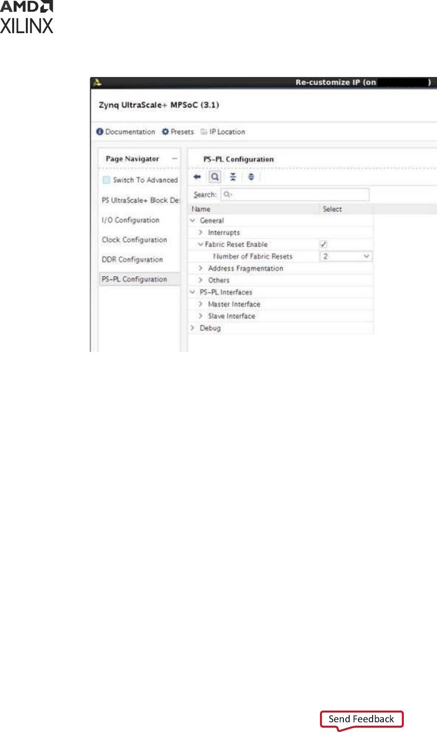
Figure 66: Resets from PS to PL
The pl_resetn signals are implemented with PS GPIOs. Pl_resetn pins are released aer
bitstream conguraon in soware using the psu_ps_pl_reset_config_data funcon. In
the case where a subsystem also uses GPIO for purpose other than reset, the GPIO block is
included in the subsystem denion. The image below shows an example of an APU subsystem
with GPIO as a slave peripheral.
Chapter 12: Reset
UG1137 (v2022.2) November 2, 2022 www.xilinx.com
Zynq UltraScale+ MPSoC: Software Developers Guide 233

Figure 67: APU Subsystem with GPIO
In the case where GPIO is a subsystem slave peripheral, the enre GPIO component will be reset
as part of the restart process when the subsystem is being restarted. Since pl_resetn are
implemented with GPIOs, pl_resetn will be forced low during subsystem restart. This behavior
may be undesirable if the pl_resent signals are being used to drive PL IPs in subsystems other
than the one being reset. For example, if pl_resetn0 drives resets to PL IP for APU subsystem
and pl_resetn1 drives PL IPs for RPU subsystem.
During APU subsystem restart, both pl_resetn0 and pl_resent1 will be forced into the
reset state. Consequently, PL IPs in RPU subsystem will be reset. This is the wrong behavior since
APU-restart should not aect the RPU subsystem as the GPIO is implicitly shared between the
APU and RPU subsystem via pl_resetn signals. Since sharing of peripherals is not supported
for subsystem restart, pl_resetn causes problems during subsystem reset. The work-around is
to skip idling and reseng GPIO peripheral during any subsystem restart even if the component
is assigned in the subsystem/isolaon conguraon.
To skip the GPIO reset during the node Idling and reset, build the PMU rmware with following
ag:
REMOVE_GPIO_FROM_NODE_RESET_INFO
Note: GPIO component goes through a reset cycle also during PS-only reset. PMU rmware enables PS-PL
isolaon prior to calling PS only reset which locks pl_resetn to High. However, as soon as FSBL removes
the PS-PL isolaon, the reset goes Low. FSBL then calls psu_ps_pl_reset_config_data to
recongure pl_resetn back to High. This is needed since reseng the PL components allows proper
synchronizaon of soware and hardware states aer reset.
Chapter 12: Reset
UG1137 (v2022.2) November 2, 2022 www.xilinx.com
Zynq UltraScale+ MPSoC: Software Developers Guide 234

Recovering from a Hang System
In an event of system hang, as indicated by FPT WDT meout, PMU can be used to carry out a
sequence of events to try and recover from the unresponsive condion. By default, when FPD
WDT mes out, PMU rmware will not invoke any type of restart. This is so that user can specify
the exact desired behavior. However, Xilinx provides a typical recovery scheme in which PMU
rmware monitors the state of APU subsystem using FPD WDT and restart APU (Linux)
subsystem if the mer expires, indicang problem with Linux.
Since RPU subsystem is managed by Linux using remoteproc, the life-cycle of the RPU subsystem
is completely up to Linux. PMU is not involved in deciding when to restart RPU subsystem(s).
RPU hang recovery can also be implemented with help of either soware or hardware watchdog
between APU and RPU subsystems. In that case, the watchdog is congured and handled by
Linux but the heartbeats is provided by RPU applicaon(s). The exact method of deciding when
to restart RPU is up to the user, watchdog is simply one of many possibilies. To enable recovery,
PMU rmware should be built with enabling error management and recovery. Following macros
enable the Recovery feature:
• ENABLE_EM
• ENABLE_RECOVERY
It is also necessary to build TF-A with following ags (see APU Idling for details):
ZYNQMP_WARM_RESTART=1
IMPORTANT!
One TTC mer (mer 9) will be reserved for PMU's use when these compile ags are
enabled.
Watchdog Management
The FPD WDT is used for monitoring APU state. Soware running on APU periodically touch
FPD WDT to keep it from ming out. The occurrence of WDT meout indicates an unexpected
condion on the APU which prevents the soware from running properly and an APU restart is
invoked. FPD WDT is congured by PMU rmware at inializaon stage, but is periodically
serviced by soware running on APU.
The default meout congured for WDT is 60 seconds and can be changed by
RECOVERY_TIMEOUT ag in PMU rmware. When APU subsystem goes into a restart cycle,
FPD WDT is kept running to ensure that the restart lands in a clean running state where soware
running on APU is able to touch the WDT again. Therefore, the meout for the WDT must be
long enough to cover the enre APU subsystem restart cycle to prevent the WDT from ming
out in the middle of restart process. It is advisable to start providing the heartbeat as soon as is
Chapter 12: Reset
UG1137 (v2022.2) November 2, 2022 www.xilinx.com
Zynq UltraScale+ MPSoC: Software Developers Guide 235

feasible in Linux. PetaLinux BSP includes recipe to add the watchdog management service in
init.d. As FPD WDT is owned by PMU rmware, it would be unsafe to use full edged Linux
driver for handling WDT. It is advisable to just pump the heartbeats by wring restart key
(0x1999) to restart register (WDT base + 0x8) of the WDT. It can be done through C program
daemon or it can be part of bash script daemon.
It is recommended to be part of idle thread or similar low priority thread, which if hangs you
should consider the subsystem hang.
The following is the snippet of the single heartbeat stroke to the FPD WDT from command
prompt. This can be included in the bash script which runs periodically.
# devmem 0xFD4D0008 32 0x1999
The following wdt-heartbeat applicaon periodically provides the heartbeat to FPD WDT. For
demo purpose this applicaon is launched as daemon. The code from this applicaon can be
implemented in appropriate locaon such as an idle thread of Linux.
#include <stdio.h>
#include <sys/mman.h>
#include <fcntl.h>
#include <unistd.h>
#define WDT_BASE 0xFD4D0000
#define WDT_RESET_OFFSET 0x8
#define WDT_RESET_KEY 0x1999
#define REG_WRITE(addr, off, val) (*(volatile unsigned int*)(addr
+off)=(val))
#define REG_READ(addr,off) (*(volatile unsigned int*)(addr+off))
void wdt_heartbeat(void)
{
char *virt_addr; int fd;
int map_len = getpagesize();
fd = open("/dev/mem", (O_RDWR | O_SYNC)); virt_addr = mmap(NULL,
map_len, PROT_READ|PROT_WRITE,
MAP_SHARED,
fd, WDT_BASE);
if (virt_addr == MAP_FAILED) perror("mmap failed");
close(fd);
REG_WRITE(virt_addr,WDT_RESET_OFFSET, WDT_RESET_KEY);
munmap((void *)virt_addr, map_len);
}
int main()
{
while(1)
{
wdt_heartbeat(); sleep(2);
}
return 0;
}
Chapter 12: Reset
UG1137 (v2022.2) November 2, 2022 www.xilinx.com
Zynq UltraScale+ MPSoC: Software Developers Guide 236

On the expiry of watchdog, PMU rmware receives and handles the WDT interrupt. PMU
rmware idles the subsystem's master CPU i.e., all A53 cores (see APU Idling), and then carries
out APU only restart ow which includes CPU reset and idling and reseng peripherals (see
Peripheral Idling) associated to the subsystem reset.
Note: If ESCALATION is enabled PMU rmware will trigger the appropriate restart ow (which can be
other than APU only restart) as explained in Escalaon secon.
APU Idling
Each A53 is idled by taking them to the WFI state. This is done through Trusted Firmware-A (TF-
A). For idling CPU, the PMU rmware raises TTC interrupt (mer 9) to TF-A, which issues
soware interrupt to each alive A53 core. The respecve cores then clears the pending SGI on
itself and put itself into WFI.
The last core just before going into WFI issues pm_system_shutdown (PMU rmware API) to
PMU rmware, which then performs APU only restart ow.
This feature must be enabled in TF-A for recovery to work properly. It can be enabled by building
TF-A with ZYNQMP_WARM_RESTART=1 ag.
Modifying Recovery Scheme
When ENABLE_RECOVERY is turned on, Xilinx provides a recovery implementaon in which a
FPD WDT meout results in the invocaon of APU subsystem restart. You can easily modify the
recovery behavior by modifying the code. Alternavely, an example of PMU rmware invoking
system-reset on FPD WDT meout is detailed in Xilinx Answer: 69423.
Escalation
If current recovery cannot bring the system back to the working state, the system must escalate
to a more severe type of reset on the next WDT expiry in order to try and recover fully. It is up to
you to decide on the escalaon scheme. A commonly used scheme starts with APU-restart on
the rst watchdog expiraon, followed by PS-only reset on the next watchdog expiraon, then
nally system-reset.
To enable escalaon, PMU rmware must be built with following ags:
ENABLE_ESCALATION
Escalation Scheme
Chapter 12: Reset
UG1137 (v2022.2) November 2, 2022 www.xilinx.com
Zynq UltraScale+ MPSoC: Software Developers Guide 237

Default Scheme
Default escalaon scheme checks for the successful pm_system_shutdown call from TF-A for
APU-only restart which happens when the TF-A is able to successfully idle all acve CPUs. If TF-
A is not successful in idling the acve cores, WDT will me out again with the WDT_in_Progess
ag set, resulng in do escalaon.
Escalaon will trigger System level reset. System level reset is dened as PS only reset if PL is
present or System restart if PL is not present.
The following gure shows the ow of the control in case of default escalaon scheme.
Figure 68: Flow of Control for Default Escalation Scheme
Is WDT_In_Progress
Raise Interrupt to
PMU Firmware
No
Do
Escalation
Restart WDT
Set WDT_in_Progress flag
Raise IPI request to ATF for Clearing APU
Sleep and
wait for
event
Restart WDT
Clear WDT_in_Progress flag
Do APU only
restart
Clear all the pending
interrupts on this core
ATF Raises Sw interrupts
for all Active cores
Is Last Active
Core?
Call Pm System shutdown
call for APU only reset
WFI
Each Active core invoked runs same codeIPI to ATF
IPI to PMU-firmware
Legends
AM Trusted Firmware
Hardware
PMU Firmware
Yes
FPD
WDT
Expired
X21016-060618
Chapter 12: Reset
UG1137 (v2022.2) November 2, 2022 www.xilinx.com
Zynq UltraScale+ MPSoC: Software Developers Guide 238

Healthy Bit Scheme
Default scheme for escalaon does not guarantee the successful reboot of the system. It only
guarantees the successful role of TF-A to idle the CPU during the recovery. Consider the scenario
in which the FPD_WDT has med out and APU subsystem restart is called in which TF-A is able
to successfully make the pm_system_shutdown call. However, APU subsystem restart is far
from nished aer pm_system_shutdown is called. The restart process can be stuck
elsewhere, such as fsbl, u-boot or Linux init state. If the restart process is stuck in one of the
aforemenoned tasks, FPD_WDT will expire again, causing the same cycle to be repeated as long
as TF-A is loaded and funconing. This cycle can connue indenitely without the system
boong back into a clean running state.
The Healthy Bit scheme solves this problem. In addion to default scheme, the PMU rmware
checks for a Healthy Bit, which is set by Linux on successful boong. On WDT expiry, if Healthy
Bit is set, it indicates that Linux is able to boot into a clean running state, then no escalaon is
needed. However, if Healthy Bit is not set, that means the last restart aempt did not
successfully boot into Linux and escalaon is needed. There is no need to repeat the same type
of restart. PMU rmware will escalate and call a system level reset.
Healthy Bit scheme is implemented using the bit-29 of PMU global general storage register
(PMU_GLOBAL_GLOBAL_GEN_STORAGE0[29]). PMU rmware clears the bit before starng the
recovery or normal reboot and Linux must set this bit to ag a healthy boot.
PMU global registers are accessed through sysfs interface from Linux. Hence, to set the healthy
bit from the Linux, execute the following command (or include in the code):
# echo "0x20000000 0x20000000" > "/sys/devices/platform/firmware/ggs0"
To enable the healthy bit based escalaon scheme, build the PMU rmware with the following
ag:
CHECK_HEALTHY_BOOT
The following gure shows the ow of the control in case of the healthy bit escalaon scheme.
Chapter 12: Reset
UG1137 (v2022.2) November 2, 2022 www.xilinx.com
Zynq UltraScale+ MPSoC: Software Developers Guide 239

Figure 69: Healthy Bit Escalation Scheme
Is WDT_In_Progress
Healthy Bit Set?
FPD
WDT
Expired
Raise Interrupt to
PMU Firmware
No
Do
Escalation
No
Restart WDT
Yes
Set WDT_in_Progress flag
Raise IPI request to ATF for Clearing APU
Sleep and
wait for
event
Restart WDT
Clear WDT_in_Progress flag
Do APU only
restart
Clear all the pending
interrupts on this core
ATF Raises Sw interrupts
for all Active cores
Is Last Active
Core?
Call Pm System shutdown
call for APU only reset
WFI
Each Active core invoked runs same codeIPI to ATF
IPI to PMU-firmware
Legends
AM Trusted Firmware
Hardware
PMU Firmware
Yes
X21015-060618
Customizing Recovery and Escalation Scheme
By default, when FPD WDT mes out, PMU FW will not invoke any type of restart. While Xilinx
has provided predened RECOVERY and ESCALATION behaviors, users can easily customize
dierent desired schemes.
When FPD _WDT mes out, it calls FpdSwdtHandler. If ENABLE_EM is dened,
FpdSwdtHandler calls XPfw_recoveryHandler. It is otherwise an empty funcon.
Chapter 12: Reset
UG1137 (v2022.2) November 2, 2022 www.xilinx.com
Zynq UltraScale+ MPSoC: Software Developers Guide 240

In xpfw_mod_em.c,
#ifdef ENABLE_EM
oid FpdSwdtHandler(u8 ErrorId)
{
XPfw_Printf(DEBUG_ERROR,"EM: FPD Watchdog Timer Error (Error ID: %d)\r\n",
ErrorId);
XPfw_RecoveryHandler(ErrorId);
}
#else
void FpdSwdtHandler(u8 ErrorId) { }
Without ENABLE_EM, you can simply update FpdSwdtHandler which will be called at FPD
Timeout. With ENABLE_EM turned on, you need to update XPfw_recoveryHandler.
Similarly, turning on RECOVERY denes the XPfw_RecoveryHandler (see
xpfw_restart.c). Unless RECOVERY is turned on, XPfw_ RecoveryHandler is an empty
funcon and nothing will happen when FPD_WDT mes out.
RecoveryHandler basically follows the ow chart detailed in the Escalaon Scheme secon.
When FPD_WDT mes out, the code follows the progression of orange boxes. If WDT is not
already in progress, Restart WDT, Set WDT_In_Progress ag, Raise TTC (mer 9) interrupt to TF-
A. Then TF-A takes over. It Raises SW interrupt for all acve cores, clear pending interrupts, etc.
(see blue boxes). Essenally, PMU restarts and boosts the WDT, then sends a request to TF-A.
TF-A cleanly idles all four APUs and when they all get to WFI (Last Acve Core is true), TF-A
issues PMU System Shutdown with APU subsystem as argument back to PMU. When PMU gets
this command, it invokes APU subsystem restart.
If ENABLE_ESCALATION is not set, the code never takes the Do Escalaon path. If the
RecoveryHandler hangs for some reason (for example, something went wrong and APU
cannot put all four CPU cores to WFI), it keeps retrying APU restart or hang forever. When
ENABLE_ESCLATION is on and if anything goes wrong during execuon of the owchart, it will
look like WDT is sll in progress (since clear WDT_in_progress ag happens only as the last step),
Do Escalaon will call SYSTEM_RESET instead of trying APU-restart again and again.
To customize recovery and escalaon behavior, use the provided XPfw_recoveryHandler as a
template to provide a customized XPfw_recoveryHandler funcon.
Building Software
All the soware components are built and packaged by Xilinx PetaLinux tool. See PetaLinux wiki
page for more informaon on how to build and package soware components.
Build Flag for Restart Solution
Following build me ags are not set by default and can alter the behavior of the restart in
Zynq UltraScale+ MPSoC:
Chapter 12: Reset
UG1137 (v2022.2) November 2, 2022 www.xilinx.com
Zynq UltraScale+ MPSoC: Software Developers Guide 241

Table 63: Build Time Flags
Component Flag Name Description
PMU firmware
ENABLE_EM
Enable error management and
provide WDT interrupt handling.
This is not directly related to
restart solution but needed for
recovery.
ENABLE_RECOVERY
Enable Recovery during WDT
expiry
ENABLE_ESCALATION Allow escalation on failure of boot
or recovery
CHECK_HEALTHY_BOOT Use Healthy bit to determine
escalation
IDLE_PERIPHERALS ENABLE_NODE_IDLING Both the flags must be used
together to allow PMU firmware to
attempt peripherals node idling
(and reset).
REMOVE_GPIO_FROM_NODE_RESET_INFO Skips GPIO from the node idling
and resetting list.
This is needed when the system is
using GPIO to provide reset (or
similar) signals to PL or other
peripherals outside current
subsystem.
If this flag is set, GPIO is not reset.
TF-A
ZYNQMP_WARM_RESTART=1 Enable WARM RESTART recovery
feature in TF-A that allow the CPU
idling triggered from PMU
firmware.
FSBL FSBL_PROT_BYPASS Skip XMPU/XPPU based
configuration for system except
for DDR and OCM.
Linux CONFIG_SRAM Needed for Remoteproc to work
for load RPU images in the TCM.
Modifying Component Recipes
Each component's recipe can be changed to either include the build me compilaon ags or to
include patches for custom code modicaon/addion. PetaLinux provides meta-user Yocto
based layer for user specic modicaons. The layer can be found in project directory project-
spec/meta-user/ locaon.
PMU Firmware
User specic recipe for PMU rmware can be found in the following locaon:
dir:project-spec/meta-user/recipes-bsp/pmu/pmu-firmware_%.bbappend (if
doesn't exist please create this le at this path).
Chapter 12: Reset
UG1137 (v2022.2) November 2, 2022 www.xilinx.com
Zynq UltraScale+ MPSoC: Software Developers Guide 242

The PMU rmware code can be modied by patches against embeddedsw GitHub repo. Locaon
for the source code is embeddedsw/tree/master/lib/sw_apps/zynqmp_pmufw. The
patches should be copied to project-spec/meta-user/recipes-bsp/pmu/files
directory and the same patch names should be added pmu-firmware_%.bbappend le.
Example:
If my_changes.patch (against PMU rmware source) is to be added and all the ags explained
in the Build Time Flags in Building Soware are to be enabled (set), then project-spec/
meta-user/recipes-bsp/pmu/pmu-firmware_%.bbappend may look like the following
le:
YAML_COMPILER_FLAGS_append = " -O2 -DENABLE_EM -DENABLE_RECOVERY
-DENABLE_ESCALATION -DENABLE_NODE_IDLING -DREMOVE_GPIO_FROM_NODE_RESET_INFO
-DCHECK_HEALTHY_BOOT -DIDLE_PERIPHERALS"
FILESEXTRAPATHS_prepend := "${THISDIR}/files:" SRC_URI_append = " file://
my_changes.patch"
FSBL
User specic recipe for the FSBL can be found in the following locaon:
dir:project-spec/meta-user/recipes-bsp/fsbl/fsbl_%.bbappend (if does not
exist, please create this le at this path). The FSBL code can be modied by patches against
embeddedsw GitHub repo. Locaon for the source code is as follows:
embeddedsw/tree/master/lib/sw_apps/zynqmp_fsbl
The patches should be copied to project-spec/meta-user/recipes-bsp/fsbl/files
directory and the same patch names should be added to fsbl_%.bbappend le.
Example:
If my_changes.patch (against the FSBL source) is to be added and all the ags explained in the
Build Time Flags in Building Soware are to be enabled (set), then the modied project-
spec/meta-user/recipes-bsp/fsbl/fsbl_%.bbappend le will look like the following
le (XPS_BOARD_ZCU102 ag was already exisng):
YAML_COMPILER_FLAGS_append = " -DXPS_BOARD_ZCU102 -DFSBL_PROT_BYPASS"
FILESEXTRAPATHS_prepend := "${THISDIR}/files:"
SRC_URI_append = " file://my_changes.patch"
TF-A
User specic recipe for TF-A can be found in the following locaon:
dirproject-spec/meta-user/recipes-bsp/arm-trusted-firmware/arm-
trusted-firmware_%.bbappend le (if it doesn't exist, create this le in this path). You can
nd the ATF les in Git repository for arm trusted rmware.
Chapter 12: Reset
UG1137 (v2022.2) November 2, 2022 www.xilinx.com
Zynq UltraScale+ MPSoC: Software Developers Guide 243

Example:
To add warm restart ag to TF-A, project-spec/meta-user/recipes-bsp/arm-
trusted-firmware/arm-trusted-firmware_%.bbappend will look like the following le:
#
# Enabling warm restart feature
#
EXTRA_OEMAKE_append = " ZYNQMP_WARM_RESTART=1"
Linux
There are many ways to add /modify Linux conguraon. See PetaLinux Tools Documentaon:
Reference Guide (UG1144) for the same.
User specic recipe for Linux kernel can be found in the following locaon:
project-spec/meta-user/recipes-kernel/linux/linux-xlnx_%.bbappend (if it
doesn't exist, create this le at this path).
You can nd the Linux les at Git Repository for Linux Example:
To add SRAM cong to Linux, create the following bsp.cfg le:
project-spec/meta-user/recipes-kernel/linux/linux-xlnx/bsp.cfg
CONFIG_SRAM=y
Add this le in the following bbapend le of Linux:
project-spec/meta-user/recipes-kernel/linux/linux-xlnx_%.bbappend
SRC_URI += "file://bsp.cfg"
FILESEXTRAPATHS_prepend := "${THISDIR}/${PN}:"
Modifying Device Tree
User specic recipe for device tree can be found in the following locaon:
project-spec/meta-user/recipes-bsp/device-tree/device-tree-generation_
%.bbappend. This le contains the following contents:
SRC_URI_append ="\ file://system-user.dtsi \
"
FILESEXTRAPATHS_prepend := "${THISDIR}/files:"
Chapter 12: Reset
UG1137 (v2022.2) November 2, 2022 www.xilinx.com
Zynq UltraScale+ MPSoC: Software Developers Guide 244

The content of system-user.dtsi in project-spec/meta-user/recipes-bsp/
device-tree/files directory is as follows:
/include/ "system-conf.dtsi"
/ {
};
This le can be modied to extend the device tree funconality by adding, removing, or
modifying the DTS nodes.
Example: Adding DT node(s) [ remoteproc RPU split mode]
The overlay dtsi(s) can be added in les/ directory (remember to update bbappend le
accordingly) and included in system-user.dtsi. For adding remoteproc related entries to
enable RPU subsystem to load, unload, or restart, add a new overlay le called
remoteproc.dtsi.
Note: This is for split mode. Check open amp documentaon for lockstep and other possible
conguraons.
File: remoteproc.dtsi
/ {
reserved-memory {
#address-cells = <2>;
#size-cells = <2>; ranges;
rproc_0_reserved: rproc:dir3ed000000 { no-map;
reg = <0x0 0x3ed00000 0x0 0x1000000>;
};
};
power-domains {
pd_r5_0: pd_r5_0 {
#power-domain-cells = <0x0>; pd-id = <0x7>;
};
pd_r5_1: pd_r5_1 {
#power-domain-cells = <0x0>; pd-id = <0x8>;
};
pd_tcm_0_a: pd_tcm_0_a {
#power-domain-cells = <0x0>; pd-id = <0xf>;
};
pd_tcm_0_b: pd_tcm_0_b {
#power-domain-cells = <0x0>; pd-id = <0x10>;
};
Chapter 12: Reset
UG1137 (v2022.2) November 2, 2022 www.xilinx.com
Zynq UltraScale+ MPSoC: Software Developers Guide 245

pd_tcm_1_a: pd_tcm_1_a {
#power-domain-cells = <0x0>;
pd-id = <0x11>;
};
pd_tcm_1_b: pd_tcm_1_b {
#power-domain-cells = <0x0>; pd-id = <0x12>;
};
};
amba {
r5_0_tcm_a: tcm:dirffe00000 { compatible = "mmio-sram";
reg = <0x0 0xFFE00000 0x0 0x10000>;
pd-handle = <&pd_tcm_0_a>;
};
r5_0_tcm_b: tcm:dirffe20000 { compatible = "mmio-sram";
reg = <0x0 0xFFE20000 0x0 0x10000>;
pd-handle = <&pd_tcm_0_b>;
};
r5_1_tcm_a: tcm:dirffe90000 { compatible = "mmio-sram";
reg = <0x0 0xFFE90000 0x0 0x10000>;
pd-handle = <&pd_tcm_1_a>;
};
r5_1_tcm_b: tcm:dirffeb0000 { compatible = "mmio-sram";
reg = <0x0 0xFFEB0000 0x0 0x10000>;
pd-handle = <&pd_tcm_1_b>;
};
elf_ddr_0: ddr:dir3ed00000 { compatible = "mmio-sram";
reg = <0x0 0x3ed00000 0x0 0x40000>;
};
elf_ddr_1: ddr:dir3ed40000 { compatible = "mmio-sram";
reg = <0x0 0x3ed40000 0x0 0x40000>;
};
test_r50: zynqmp_r5_rproc:dir0 {
compatible = "xlnx,zynqmp-r5-remoteproc-1.0";
reg = <0x0 0xff9a0100 0x0 0x100>, <0x0 0xff340000 0x0 0x100>, <0x0
0xff9a0000 0x0 0x100>;
Chapter 12: Reset
UG1137 (v2022.2) November 2, 2022 www.xilinx.com
Zynq UltraScale+ MPSoC: Software Developers Guide 246

reg-names = "rpu_base", "ipi", "rpu_glbl_base"; dma-ranges;
core_conf = "split0"; sram_0 = <&r5_0_tcm_a>; sram_1 = <&r5_0_tcm_b>;
sram_2 = <&elf_ddr_0>; pd-handle = <&pd_r5_0>;
interrupt-parent = <&gic>; interrupts = <0 29 4>;
} ;
test_r51: zynqmp_r5_rproc:dir1 {
compatible = "xlnx,zynqmp-r5-remoteproc-1.0";
reg =<0x0 0xff9a0200 0x0 0x100>, <0x0 0xff340000 0x0 0x100>, <0x0
0xff9a0000 0x0 0x100>;
reg-names = "rpu_base", "ipi", "rpu_glbl_base"; dma-ranges;
core_conf = "split1"; sram_0 = <&r5_1_tcm_a>; sram_1 = <&r5_1_tcm_b>;
sram_2 = <&elf_ddr_1>; pd-handle = <&pd_r5_1>;
interrupt-parent = <&gic>; interrupts = <0 29 4>;
} ;
};
};
Now include this node in system-user.dtsi:
/include/ "system-conf.dtsi"
/include/ "remoteproc.dtsi"
/ {
};
For informaon on OpenAMP and remoteproc, see the OpenAmp wiki page.
Example: Removing DT node(s) [ PL node]
It is necessary to remove PL nodes, which are not accessed or dependent on APU subsystem,
from the device tree. Again, you can modify system-user.dtsi in project-spec/meta-
user/recipes-bsp/device-tree/files to remove specic node or property.
For example, you can modify the system-user.dtsi as following, if you are willing to remove
AXI DMA node from the dts:
/include/ "system-conf.dtsi"
/include/ "remoteproc.dtsi"
/ {
/delete-node/axi-dma;
};
Chapter 12: Reset
UG1137 (v2022.2) November 2, 2022 www.xilinx.com
Zynq UltraScale+ MPSoC: Software Developers Guide 247

Chapter 13
High-Speed Bus Interfaces
The Zynq
®
UltraScale+™ MPSoC has a serial input/output unit (SIOU) for a high-speed serial
interface. It supports protocols such as PCIe
®
, USD 3.0, DisplayPort, SATA, and Ethernet
protocols.
• The SIOU block is part of the full-power domain (FPD) in the PS.
• The USB and Ethernet controller blocks that are part of the low-power domain (LPD) in the
Zynq UltraScale+ MPSoC also share the PS-GTR transceivers.
• The interconnect matrix enables mulplexing of four PS-GTR transceivers in various
combinaons across mulple controller blocks.
• A register block controls or monitors signals within the SIOU.
This chapter explains the conguraon ow of the high-speed interface protocols.
See this link to the “High-Speed PS-GTR Transceiver Interface” of the Zynq UltraScale+ Device
Technical Reference Manual (UG1085) for more informaon.
USB 3.0
The Zynq UltraScale+ MPSoC USB 3.0 controller consists of two independent dual-role device
(DRD) controllers. Both can be individually congured to work as host or device at any given
me. The USB 3.0 DRD controller provides an eXtensible host controller interface (xHCI) to the
system soware through the advanced eXtensible interface (AXI) slave interface.
• An internal DMA engine is present in the controller and it uses the AXI master interface to
transfer data.
• The three dual-port RAM conguraons implement the RX data FIFO, TX data FIFO, and the
descriptor/register cache.
The following ow diagrams illustrate how to congure USB as mass storage device.
Chapter 13: High-Speed Bus Interfaces
UG1137 (v2022.2) November 2, 2022 www.xilinx.com
Zynq UltraScale+ MPSoC: Software Developers Guide 248
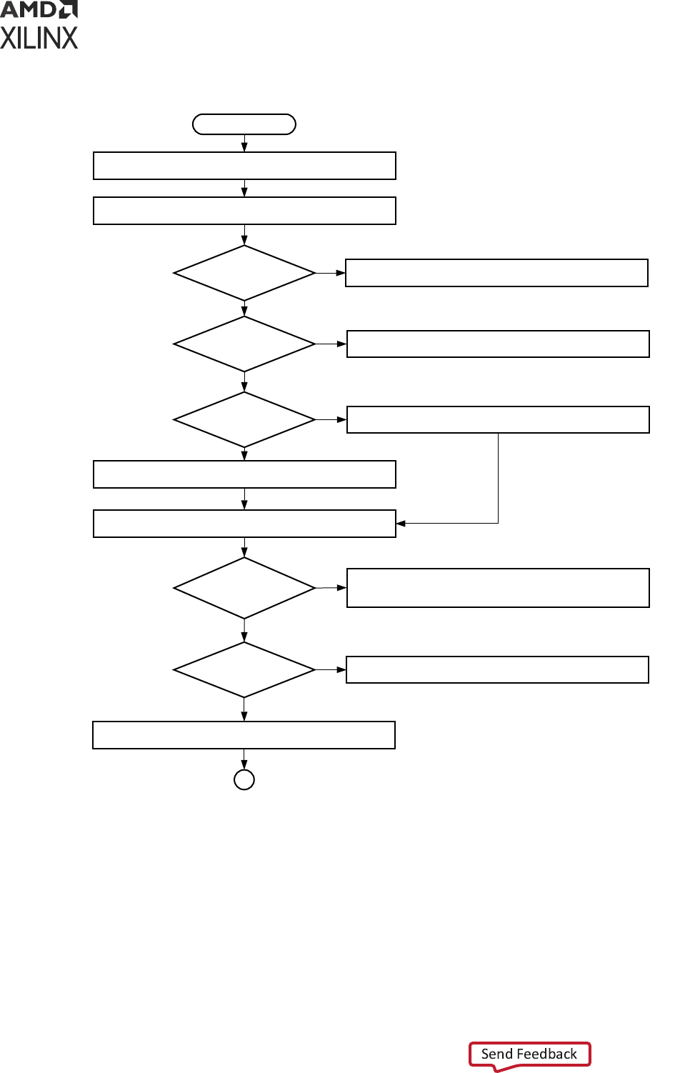
Figure 70: USB Example Flow: USB Initialization
USB config initialize
Start
Call a function to hook up the handler for control packets
Is Req type==
Std dev req?
Stall on endpoint 0
Call a function to hook up the handler for mass storage
Stall the endpoint 0
Handle standard device request
Is Req type==
class req?
Handle the class request
Is Req type==
vendor req?
Do nothing
Is Req ==
Mass storage
reset?
Do nothing
(Status phase is handled by driver)
Is Req ==
Get_Maz_LUN
Prepare a URB with number of LUNs
Yes
Yes
Yes
Yes
Yes
No
No
No
No
No
A
X15463-111020
Chapter 13: High-Speed Bus Interfaces
UG1137 (v2022.2) November 2, 2022 www.xilinx.com
Zynq UltraScale+ MPSoC: Software Developers Guide 249

Figure 71: Example USB Flow: Hookup Bulk in and Bulk out Handlers and Initialize
Interrupt Controller
Prepare device descriptors
Prepare configuration descriptors
Call a function to hook up the bulkout handler
Is phase ==
Data?
Send command status wrapper (CSW)
Call a function to hook up the bulk In handler
Read the packet data into Receive Buffer
Is phase ==
Status?
Initialize the driver interrupt controller
Config initialize for GIC
Connect the interrupt controller
Is phase ==
Command?
Parse CBW
Send reduced block command (RBC)
Write operation
Is phase ==
Data?
Is
RBC
Mode sense ==
1?
Send CSW with mode
Yes
Yes
No
No
Yes
No
Yes
Yes
Send CSW with mode
No
No
B
A
X15477-071017
Chapter 13: High-Speed Bus Interfaces
UG1137 (v2022.2) November 2, 2022 www.xilinx.com
Zynq UltraScale+ MPSoC: Software Developers Guide 250

Figure 72: Enable Interrupts and Start the USB Controller
Enable all the required interrupts
Connect the interrupt controller to the interrupt
handling logic in ARM
Enable interrupts in the ARM
Wait for interrupts
Start USB Controller
B
X15478-021317
For more informaon on USB controller, see this link to the “USB 2.0/3.0 Host, Device, and
Controller,” chapter of the Zynq UltraScale+ Device Technical Reference Manual (UG1085).
Gigabit Ethernet Controller
The gigabit Ethernet controller (GEM) implements a 10/100/1000 Mb/s Ethernet MAC
compable with IEEE Standard for Ethernet (IEEE Std 802.3-2008) and is capable of operang in
either half or full-duplex mode in 10/100 mode and full-duplex in 1000 mode.
The processor system (PS) is equipped with four gigabit Ethernet controllers. Registers are used
to congure the features of the MAC, and select dierent modes of operaon. The DMA
controller connects to memory through the advanced eXtensible interface (AXI). It is aached to
the FIFO interface of the controller of the MAC to provide a scaer-gather type capability for
packet data storage in an embedded processing system.
The following gures illustrate an example for conguring an Ethernet controller to send a single
packet of data in RGMII mode.
Chapter 13: High-Speed Bus Interfaces
UG1137 (v2022.2) November 2, 2022 www.xilinx.com
Zynq UltraScale+ MPSoC: Software Developers Guide 251

Figure 73: Example Ethernet Flow: Initialize Ethernet Controller
Start
Setup UART
Get the Configuration of Ethernet
Hardware
Get Cache Coherence Selection
Initialize Ethernet hardware, setup interrupts and
callbacks
Error in initializing?
Return error and exit
Set the MAC address
Set the loopback speed to 1G
Get the PHY interface
Detect the PHY address
Read the PHY Model
Yes
No
A
X15462-071017
Chapter 13: High-Speed Bus Interfaces
UG1137 (v2022.2) November 2, 2022 www.xilinx.com
Zynq UltraScale+ MPSoC: Software Developers Guide 252

Figure 74: Example Ethernet Flow: Configure the Ethernet Parameters & Initiate the
Transmit
Clear the PHY of any existing bits
RGMII mode PHY specific register initialization
Configure the Interface modes
Set the speed and put the PHY in reset
Put the PHY in loopback
Return Error and Exit
Error Setting the
PHY loopback?
Set PHY <-> MAC Data clock
Delay
Setup BD space
Setup attributes of BD space
Set up the packet to be transmitted
Clear out the receive packet memory area
Calculate the frame length (not including FCS)
Setup BD Rings and push the Frame
Start the Ethernet Device and Initiate Transmit
Wait for status of the transmitted packet
No
Yes
A
B
X15479-071017
Chapter 13: High-Speed Bus Interfaces
UG1137 (v2022.2) November 2, 2022 www.xilinx.com
Zynq UltraScale+ MPSoC: Software Developers Guide 253

Figure 75: Example Ethernet Flow: Receive and Validate the Data
Wait for status of the transmitted packet
Receive the packet
Return error and exit
Error
Get the length of the arrived data
Read the packet data received
Verify the received frame length
Validate the frame data
Stop Ethernet Hardware and disable
Interrupts
No
Yes
Stop
B
X15480-021317
For more informaon on Ethernet Controller, see this link to the “Gigabit Ethernet Controller”
chapter in the Zynq UltraScale+ Device Technical Reference Manual (UG1085).
PCI Express
The Zynq UltraScale+ MPSoC provides a controller for the integrated block for PCI™ Express
v2.1 compliant, AXI-PCIe Bridge, and DMA modules. The AXI-PCIe Bridge provides high-
performance bridging between PCIe and AXI.
Chapter 13: High-Speed Bus Interfaces
UG1137 (v2022.2) November 2, 2022 www.xilinx.com
Zynq UltraScale+ MPSoC: Software Developers Guide 254

The following ow diagrams illustrate an example for conguring PCIe root complex for a data
transfer.
Figure 76: Example PCIe Flow: Enable the Legacy Interrupts and Create PCIe Root Bus
Map the register memory space for PCIe bridge
and controller
Start
Map the memory space for ECAM
Write the bridge offset in the bridge register base
Enable the bridge in the bridge control register
Disable the DMA channel registers
Enable the bridge configuration interrupt
Enable Ingress Subtractive decode translation
Enable message filtering
Get the PCIe link up
ECAM
Bit==1
?
Return error and exit
Enable ECAM in ECAM control register
Yes
No
A
X15481-071217
Chapter 13: High-Speed Bus Interfaces
UG1137 (v2022.2) November 2, 2022 www.xilinx.com
Zynq UltraScale+ MPSoC: Software Developers Guide 255

Figure 77: Example PCIe Flow: Enable the Legacy Interrupts and Create PCIe Root Bus
Get the legacy interrupt number
Return error and exit
Invalid interrupt
number
Register the legacy interrupt handler
Return error and exit
Failed to
register handle?
Enable all legacy interrupts
Get the bridge resources
Error getting
resources?
Create PCIe root bus
Return error and exit
Return error and exit
Error creating
root bus?
Yes
Yes
Yes
Yes
No
No
No
No
A
B
X15483-043021
Chapter 13: High-Speed Bus Interfaces
UG1137 (v2022.2) November 2, 2022 www.xilinx.com
Zynq UltraScale+ MPSoC: Software Developers Guide 256

Figure 78: Example PCIe Flow: Enable MSI Interrupts and Wait for Interrupts
Assign MSI chip hooks
No
Create the IRQ domain
Enable MSII and MSII status
Error creating
IRQ domain?
Return error and exit
Yes
No
MSII bit Present?
No
Write the MSII low and high addresses
Disable and clear all high range MSI interrupts
Get the MSI_1 IRQ number
Disable and clear all low range MSI interrupts
Get the MSI_0 IRQ number
Enable all low range interrupts
Enable all high range interrupts
Remove the Interrupt Domain
Error Registering
MSI_0 handle?
No
Yes
Register the MSI_0 handle
Error getting the IRQ number?
No
Error Registering
MSI_1 handle?
Yes
Yes
Register the MSI_1 handle
Error getting the IRQ number?
Yes
Yes
No
No
Is MSI bit set?
Yes
B
Scan the PCIe child bus
Assign unassigned bus resoources
Add PCIe bus devices
Set the platform driver data
Wait for interrupts
X15484-043021X15484-071217
Note: For endpoint operaon, refer to this link to “Controller for PCI Express” in the Zynq UltraScale+ Device
Technical Reference Manual (UG1085).
Aer the memory space for PCIe bridge and ECAM is mapped, ECAM is enabled for ECAM
translaons. You then acquire the bus range to set up the bus numbers, and write the primary,
secondary, and subordinate bus numbers. The interrupt system must be set up by enabling all the
miscellaneous and legacy interrupts. You can parse the ranges property of a PCI host bridge
device node, and setup the resource mapping based on its content.
Chapter 13: High-Speed Bus Interfaces
UG1137 (v2022.2) November 2, 2022 www.xilinx.com
Zynq UltraScale+ MPSoC: Software Developers Guide 257

To create a root bus, allocate the PCIe root bus and add inial resources to the bus. If the MSI bit
is set, you must enable the message signaling interrupt (MSI). Aer conguring the MSI
interrupts, scan the PCIe slot and enumerate the enre PCIe bus and allocate bus resources to
scanned buses. Now, you can add PCIe devices to the system.
For more informaon on PCI Express, see this link to the “DMA Controller” secon and this link
to “Controller for PCI Express” in the Zynq UltraScale+ Device Technical Reference Manual
(UG1085).
Chapter 13: High-Speed Bus Interfaces
UG1137 (v2022.2) November 2, 2022 www.xilinx.com
Zynq UltraScale+ MPSoC: Software Developers Guide 258

Chapter 14
Clock and Frequency Management
The Zynq
®
UltraScale+™ MPSoC architecture includes a programmable clock generator that
takes a clock of a denite input frequency and generates mulple-derived clocks using the
phase-locked loop (PLL) blocks in the PS. The output clock from each of the PLLs is used as a
reference clock for the dierent PS peripherals.
Unlike the USB and Ethernet peripherals, some peripherals like the UART and SD allow you to
dynamically change the device frequency seng.
This chapter provides informaon about changing the operang frequency of these peripherals
dynamically. See Chapter 11: Power Management Framework for more informaon on reducing
or adjusng the clock frequencies.
Changing the Peripheral Frequency
You can change the peripheral operaon frequency by directly seng the frequency in the
corresponding peripheral clock conguraon register. The Zynq UltraScale+ MPSoC BSP
provides APIs that aid in changing the peripheral clock frequency dynamically according to your
requirements.
The following table shows the standalone APIs that can be used to change the frequency of the
peripherals
Table 64: Standalone APIs
APIs Description
XSDPS_change_clkfreq Change the clock frequency of SD.
XSPIPS_setclkprescaler XSPIPS_getclkprescaler Pre-scale the SPI frequency.
XRtcPSu_calculatecalibration Change the oscillator frequency.
XQSPIPSU_setclkprescaler Change the clock frequency of QSPI.
Chapter 14: Clock and Frequency Management
UG1137 (v2022.2) November 2, 2022 www.xilinx.com
Zynq UltraScale+ MPSoC: Software Developers Guide 259

In case of a Linux applicaon, the frequency of all the peripherals is set in the device tree le. The
following code snippet shows the seng of peripheral clock.
ps7_qspi_0: ps7-qspi:dir0xFF0F0000 {
#address-cells = <0x1>;
#size-cells = <0x0>;
#bus-cells = <0x1>;
clock-names = “ref_clk”, “pclk”;
compatible = “xlnx,usmp-gqspi”, “cdns,spi-r1p6”; stream-connected-dma =
<0x26>;
clocks = <0x1e 0x1e>; dma = <0xb>; interrupts = <0xf>;
num-chip-select = <0x2>;
reg = <0x0 0xff0f0000 0x1000 0x0 0xc0000000 0x8000000>;
speed-hz = <0xbebc200>; xlnx,fb-clk = <0x1>;
xlnx,qspi-clk-freq-hz = <0xbebc200>; xlnx,qspi-mode = <0x2>;
To avoid any error condion, the peripheral needs to be stopped before changing the
corresponding clock frequency.
The steps to follow before changing the clock frequency for any peripheral are as follows:
1. Stop the transion pertaining to the peripheral (IP) and make it idle.
2. Stop the IP by appropriately conguring the registers.
3. Change the clock frequency of the peripheral.
4. Issue so reset to the IP.
5. Restart the IP.
For more informaon on Zynq UltraScale+ MPSoC clock generator, see this link in the “Clocking”
chapter in the in the Zynq UltraScale+ Device Technical Reference Manual (UG1085).
Chapter 14: Clock and Frequency Management
UG1137 (v2022.2) November 2, 2022 www.xilinx.com
Zynq UltraScale+ MPSoC: Software Developers Guide 260

Chapter 15
Target Development Platforms
This chapter describes various development plaorms available for the
Zynq
®
UltraScale+™ MPSoC, such as Quick Emulators (QEMU) and the Zynq UltraScale+ MPSoC
boards and kits.
QEMU
QEMU is a system emulaon model that funcons on an Intel-compable Linux host system.
Xilinx
®
QEMU implements a framework for generang custom machine models based on a
device tree passed to it using the command line. See the Xilinx Quick Emulator User Guide: QEMU
for more informaon about QEMU.
Boards and Kits
Xilinx provides the Zynq UltraScale+ MPSoC ZCU102, ZCU106, and ZCU111 Evaluaon Kits for
developers. To understand more about the evaluaon kits, see the following documentaon
pages:
• ZCU102
• ZCU106
• ZCU111
To know the dierent Zynq UltraScale+ MPSoCs, see the Zynq UltraScale+ MPSoC Products
Page.
Chapter 15: Target Development Platforms
UG1137 (v2022.2) November 2, 2022 www.xilinx.com
Zynq UltraScale+ MPSoC: Software Developers Guide 261

Chapter 16
Boot Image Creation
Zynq
®
UltraScale+™ MPSoC supports both secure and non-secure boong. While deploying the
devices in eld, it is important to prevent unauthorized or modied code from being run on these
devices. Zynq UltraScale+ MPSoC provides the required condenality, integrity, and
authencaon to host applicaons securely. For more informaon on security features, see Zynq
UltraScale+ Device Technical Reference Manual (UG1085).
Zynq UltraScale+ MPSoCs typically have many hardware and soware binaries that are used to
boot them to funcon as designed and expected. These binaries includes FPGA bitstreams,
Firmware, boot loaders, operang system, and applicaons that you select. For example: FPGA
bitstream les, rst stage boot loader (FSBL), PMU rmware, TF-A, U-Boot, Linux kernel, Roos,
device tree, standalone or RTOS applicaons and so on). Xilinx provides a standalone tool,
Bootgen, to stch all these binary images together and generate a device bootable image in a
specic format that Xilinx loader programs can interpret while loading.
Bootgen has mulple aributes and commands that dene its behavior while generang boot
images. They are secure boot image generaon, non-secure boot image generaon, Secure key
generaon, HMI Mode and so on. For complete details of how to get the Bootgen tool, the
installaon procedure, and details of Zynq Ultrascale+ Boot Image format, Bootgen commands,
aributes, and boot image generaon procedure with examples, see Bootgen User Guide
(UG1283).
Chapter 16: Boot Image Creation
UG1137 (v2022.2) November 2, 2022 www.xilinx.com
Zynq UltraScale+ MPSoC: Software Developers Guide 262

Appendix A
Libraries
See OS and Libraries Document Collecon (UG643) for informaon on API reference for the
following libraries.
• Standalone Library
• LwIP 2.1.1 Library
• XilIFS
• XilFFS
• XilSecure
• XilSkey
• XilPM
• XilFPGA
• XilMailbox
Appendix A: Libraries
UG1137 (v2022.2) November 2, 2022 www.xilinx.com
Zynq UltraScale+ MPSoC: Software Developers Guide 263

Appendix B
Additional Resources and Legal
Notices
Xilinx Resources
For support resources such as Answers, Documentaon, Downloads, and Forums, see Xilinx
Support.
Documentation Navigator and Design Hubs
Xilinx
®
Documentaon Navigator (DocNav) provides access to Xilinx documents, videos, and
support resources, which you can lter and search to nd informaon. To open DocNav:
• From the Vivado
®
IDE, select Help → Documentaon and Tutorials.
• On Windows, select Start → All Programs → Xilinx Design Tools → DocNav.
• At the Linux command prompt, enter docnav.
Xilinx Design Hubs provide links to documentaon organized by design tasks and other topics,
which you can use to learn key concepts and address frequently asked quesons. To access the
Design Hubs:
• In DocNav, click the Design Hubs View tab.
• On the Xilinx website, see the Design Hubs page.
Note: For more informaon on DocNav, see the Documentaon Navigator page on the Xilinx website.
References
Appendix B: Additional Resources and Legal Notices
UG1137 (v2022.2) November 2, 2022 www.xilinx.com
Zynq UltraScale+ MPSoC: Software Developers Guide 264

Xilinx References
1. Xilinx Third-Party Licensing Soluon Center
2. PetaLinux Product Page
3. Xilinx Vivado Design Suite – HLx Edions
4. Xilinx Third-Party Tools
5. Zynq UltraScale+ MPSoC Product Table
6. Zynq UltraScale+ MPSoC Product Advantages
7. Zynq UltraScale+ MPSoC Products Page
Zynq Devices Documentation
1. Xilinx Quick Emulator User Guide: QEMU
2. UltraScale Architecture and Product Data Sheet: Overview (DS890)
3. Isolaon Methods in Zynq UltraScale+ MPSoCs (XAPP1320)
4. Zynq UltraScale+ Device Technical Reference Manual (UG1085)
5. Zynq UltraScale+ Device Register Reference (UG1087)
6. Zynq UltraScale+ MPSoC: Embedded Design Tutorial (UG1209)
7. Zynq UltraScale+ MPSoC Processing System LogiCORE IP Product Guide (PG201)
8. UltraScale Architecture System Monitor User Guide (UG580)
9. Libmetal and OpenAMP for Zynq Devices User Guide (UG1186)
10. Embedded Energy Management Interface Specicaon (UG1200)
11. UltraFast Embedded Design Methodology Guide (UG1046)
12. Zynq-7000 SoC: Embedded Design Tutorial (UG1165)
13. Zynq-7000 SoC Soware Developers Guide (UG821)
14. UltraScale Architecture PCB Design User Guide (UG583)
15. Vivado Design Suite Documentaon
16. Bootgen User Guide (UG1283)
Vitis Software Platform and PetaLinux Documents
1. Vis Unied Soware Plaorm Documentaon
Appendix B: Additional Resources and Legal Notices
UG1137 (v2022.2) November 2, 2022 www.xilinx.com
Zynq UltraScale+ MPSoC: Software Developers Guide 265

2. OS and Libraries Document Collecon (UG643)
3. Embedded Design Tools Download
4. PetaLinux Tools Documentaon: Reference Guide (UG1144)
5. Xilinx Soware Development Kit: System Performance (UG1145)
Xilinx IP Documents
1. AXI Central Direct Memory Access LogiCORE IP Product Guide (PG034)
2. AXI Video Direct Memory Access LogiCORE IP Product Guide (PG020)
Miscellaneous Links
1. Xilinx Github
2. Embedded Development
3. Yocto
4. PetaLinux Soware Development
5. Zynq UltraScale+ Silicon Devices Page
6. Xilinx Answer: 66249
7. Vivado Quick Take Video: Vivado PS Conguraon Wizard Overview
8. Xilinx Wiki
9. Kria SOM
10. WP512
11. WP516
Third-Party References
1. Lauterbach Technologies
2. Arm Trusted Firmware
3. Xen Hypervisor
4. Arm Developer Center
5. Arm Cortex-A53 MPCore Processor Technical Reference Manual
6. Yocto Product Development
7. GNU FTP
Appendix B: Additional Resources and Legal Notices
UG1137 (v2022.2) November 2, 2022 www.xilinx.com
Zynq UltraScale+ MPSoC: Software Developers Guide 266

8. Power State Coordinaon Interface – Arm DEN 0022B.b, 6/25/2013
Revision History
The following table shows the revision history for this document.
Section
Revision Summary
11/02/2022 Version 2022.2
General updates Updated a few technical details
Please Read: Important Legal Notices
The informaon disclosed to you hereunder (the "Materials") is provided solely for the selecon
and use of Xilinx products. To the maximum extent permied by applicable law: (1) Materials are
made available "AS IS" and with all faults, Xilinx hereby DISCLAIMS ALL WARRANTIES AND
CONDITIONS, EXPRESS, IMPLIED, OR STATUTORY, INCLUDING BUT NOT LIMITED TO
WARRANTIES OF MERCHANTABILITY, NON-INFRINGEMENT, OR FITNESS FOR ANY
PARTICULAR PURPOSE; and (2) Xilinx shall not be liable (whether in contract or tort, including
negligence, or under any other theory of liability) for any loss or damage of any kind or nature
related to, arising under, or in connecon with, the Materials (including your use of the
Materials), including for any direct, indirect, special, incidental, or consequenal loss or damage
(including loss of data, prots, goodwill, or any type of loss or damage suered as a result of any
acon brought by a third party) even if such damage or loss was reasonably foreseeable or Xilinx
had been advised of the possibility of the same. Xilinx assumes no obligaon to correct any
errors contained in the Materials or to nofy you of updates to the Materials or to product
specicaons. You may not reproduce, modify, distribute, or publicly display the Materials
without prior wrien consent. Certain products are subject to the terms and condions of
Xilinx's limited warranty, please refer to Xilinx's Terms of Sale which can be viewed at hps://
www.xilinx.com/legal.htm#tos; IP cores may be subject to warranty and support terms contained
in a license issued to you by Xilinx. Xilinx products are not designed or intended to be fail-safe or
for use in any applicaon requiring fail-safe performance; you assume sole risk and liability for
use of Xilinx products in such crical applicaons, please refer to Xilinx's Terms of Sale which can
be viewed at hps://www.xilinx.com/legal.htm#tos.
Appendix B: Additional Resources and Legal Notices
UG1137 (v2022.2) November 2, 2022 www.xilinx.com
Zynq UltraScale+ MPSoC: Software Developers Guide 267

AUTOMOTIVE APPLICATIONS DISCLAIMER
AUTOMOTIVE PRODUCTS (IDENTIFIED AS "XA" IN THE PART NUMBER) ARE NOT
WARRANTED FOR USE IN THE DEPLOYMENT OF AIRBAGS OR FOR USE IN APPLICATIONS
THAT AFFECT CONTROL OF A VEHICLE ("SAFETY APPLICATION") UNLESS THERE IS A
SAFETY CONCEPT OR REDUNDANCY FEATURE CONSISTENT WITH THE ISO 26262
AUTOMOTIVE SAFETY STANDARD ("SAFETY DESIGN"). CUSTOMER SHALL, PRIOR TO USING
OR DISTRIBUTING ANY SYSTEMS THAT INCORPORATE PRODUCTS, THOROUGHLY TEST
SUCH SYSTEMS FOR SAFETY PURPOSES. USE OF PRODUCTS IN A SAFETY APPLICATION
WITHOUT A SAFETY DESIGN IS FULLY AT THE RISK OF CUSTOMER, SUBJECT ONLY TO
APPLICABLE LAWS AND REGULATIONS GOVERNING LIMITATIONS ON PRODUCT
LIABILITY.
Copyright
© Copyright 2015-2022 Advanced Micro Devices, Inc. Xilinx, the Xilinx logo, Alveo, Arx, Kintex,
Kria, Spartan, Versal, Vis, Virtex, Vivado, Zynq, and other designated brands included herein are
trademarks of Xilinx in the United States and other countries. AMBA, AMBA Designer, Arm,
ARM1176JZ-S, CoreSight, Cortex, PrimeCell, Mali, and MPCore are trademarks of Arm Limited in
the EU and other countries. The DisplayPort Icon is a trademark of the Video Electronics
Standards Associaon, registered in the U.S. and other countries. PCI, PCIe, and PCI Express are
trademarks of PCI-SIG and used under license. All other trademarks are the property of their
respecve owners.
Appendix B: Additional Resources and Legal Notices
UG1137 (v2022.2) November 2, 2022 www.xilinx.com
Zynq UltraScale+ MPSoC: Software Developers Guide 268
