
ELECTRICAL SAFETY HAZARDS HANDBOOK

Littelfuse is the global leader in circuit protection
Companies around the world have come to rely on
Littelfuse’s commitment to providing the most advanced
circuit protection solutions and technical expertise. It’s this
focus that has enabled Littelfuse to become the world’s
leading provider of circuit protection solutions.
For over 75 years, Littelfuse has maintained its focus on
circuit protection. As we expand in global reach and technical
sophistication, you can continue to count on us for solid circuit
protection solutions, innovative technologies, and industry
leading technical expertise. It is a commitment that only a
world class leader with staying power can support.
A comprehensive approach to circuit protection
Littelfuse goes well beyond efficient and comprehensive
product delivery. We offer an integrated approach to circuit
protection that includes:
A very broad, yet deep selection of products
and technologies from a single source, so you
benefit from a greater range of solutions and
make fewer compromises.
Products that comply with applicable industry
and government standards, as well as our own
uncompromising quality and reliability criteria.
Forward thinking, application-specific solutions
that provide the assurance your most demanding
requirements will be met.
Dedicated global, customer-focused and
application-specific technical support services.
•
•
•
•
The World’s Leading Provider of
Circuit Protection Solutions

LITTELFUSE ELECTRICAL SAFETY HAZARDS HANDBOOK
This Electrical Safety Hazards Handbook was developed for general education purposes only and is not intended
to replace an electrical safety-training program or to serve as a sole source of reference. The information herein is
also not intended to serve as recommendations or advice for specific situations. It is the responsibility of the user to
comply with all applicable safety standards, including the requirements of the U.S. Occupational Safety and Health
Administration (OSHA), the National Fire Protection Association (NFPA), and other appropriate governmental and
industry accepted guidelines, codes, and standards. Use the information within this Handbook at your own risk.
Littelfuse is Committed to Safety
Littelfuse has a continuing commitment to improved
electrical safety and system protection. As the leader in
circuit protection, Littelfuse offers a variety of products and
services designed to help you increase safety in your facility.
For assistance with Arc-Flash, products and services, or
application information, call 1-800-TEC-FUSE (832-3873).
Electrical Safety is a Serious Issue
Electrical Safety in the workplace is the most important
job of an electrical worker. No matter how much training
one has received or how much employers try to safeguard
their workers, Electrical Safety is ultimately the responsibil-
ity of the electrical worker. The human factor associated
with electrical accidents can be immeasurable. No one can
replace a worker or loved one that has died or suffered the
irreparable consequences of an electrical accident.

Table of Contents
Introduction 6
Why is Electrical Safety so Important? 6
Electricity Basics 8
Ohm’s Law 8
Types of Electrical Faults
9
Overloads 9
Short Circuits
9
Overcurrent Protective Devices
9
Interrupting Rating 1
0
Current Limitation 1
1
Fuses 12
Circuit Breakers 1
2
Circuit Protection Checklist 1
5
History of Electrical Safety 16
Electrical Safety Organizations 19
OSHA 19
The General Duty Clause 1
9
OSHA Regulations
19
NFPA 2
0
IEEE 2
0
NRTL 20
NEMA 2
1
ANSI 21
ASTM 21
NECA 21
Electrical Safety Codes and Standards 22
Working on Deenergized Equipment 22
Establish a Safe Work Condition 22
Working on Energized Equipment 2
3
Who is Qualified? 24
Energized Electrical Work Permit 2
4
Employer and Employee Responsibilities 2
6
Arc-Flash and Other Electrical Safety Hazards 27
Electrical Safety Hazards 27
Electric Shock 2
7
Arc-Flash and Arc Blasts 2
8
Arc-Flash Metrics 2
9
Arc-Blast Effect 3
1
Light and Sound Effects 3
1
Electrical Hazard Analysis 32
Shock Hazard Analysis 32
Approach Boundaries 3
2
Flash Hazard Analysis 3
4
Arc-Flash Calculations
35
Arc-Flash Hazard Calculation Examples 3
6
IEEE 1584 Arc-Flash Hazard Calculation 3
8
NFPA 70E Table Method 4
0
Steps Required to Use the
NFPA 70E Table Method 4
0
Minimizing Arc-Flash and Other
Electrical Hazards 42
1. Design a Safer System 42
2. Use and Upgrade to Current-limiting
Overcurrent Protective Devices 43
3. Implement an Electrical Safety Program 45
4. Observe Safe Work Practices 45
5. Use Personal Protective Equipment (PPE) 47
6. Use Warning Labels 49
7. Use an Energized Electrical Work Permit 49

8. Avoid Hazards of Improperly Selected or
Maintained Overcurrent Protective Devices 50
9. Achieve or Increase Selective Coordination 51
Electrical Safety Summary 53
Annex A 5
4
Electrical Safety Terms and Definitions 54
Annex B 61
Electrical Safety Codes and Standards 61
Annex C 63
Energized Electrical Work Permit 63
Annex D 65
Arc-Flash Calculation Steps 65
Annex E 67
Arc Flash Calculator Tables 67
Annex F 71
Resources for Electrical Safety 71
Annex G 73
References 73
Annex H 74
Electrical Safety Quiz 74
97%
of all
electricians
have been
shocked or
injured
on the job.
Safety in the workplace is job number one for
employer and employee alike. It is especially
important for those who install and service
electrical systems. Nothing can replace a
worker or loved one that has died or suffered
the irreparable consequences of an electrical
accident. No matter how much an employer
tries to safeguard its workers or how much
safety training is provided; the ultimate
responsibility lies with the worker. The human
factor is part of every accident or injury.
The purpose of this handbook is to identify
electrical safety hazards and present ways
to minimize or avoid their consequences. It
is a guide for improving electrical safety and
contains information about governmental
regulations, industry-accepted standards
and work practices. It presents ways to
meet the standards and reduce the hazards.
While parts of the standards, regulations,
and codes especially relating to electrical
safety are quoted or summarized herein, it is
the responsibility of the user to comply with
all applicable standards in their entirety.
Why is Electrical Safety so Important?
Electrical hazards have always been recognized,
yet serious injuries, deaths, and property
damage occur daily. Organizations like the US
Department of Labor and the National Safety
Council compile statistics and facts on a
regular basis. The following table demonstrates
the importance of electrical safety.
6
Introduction
Electrical Safety Hazards Overview
FACTS...
97% of all electricians have been shocked or injured on the job.
Approximately 30,000 workers receive electrical shocks yearly.
Over 3600 disabling electrical contact injuries occur annually.
Electrocutions are the 4th leading cause of traumatic occupational fatalities.
Over 2000 workers are sent to burn centers each year with severe Arc-Flash burns.
Estimates show that 10 Arc-Flash incidents occur every day in the US.
60% of workplace accident deaths are caused by burn injuries.
Over 1000 electrical workers die each year from workplace accidents.
Medical costs per person can exceed $4 million for severe electrical burns.
Total costs per electrical incident can exceed $15 million.
In the year 2002, work injuries cost Americans $14.6 billion.
•
•
•
•
•
•
•
•
•
•
•
For more information:
800-TEC-FUSE
www.littelfuse.com
Information derived from Industry Surveys, the NFPA, The National Safety Council, Bureau of Labor Statistics, and CapSchell, Inc.

The moral obligation to protect workers
who may be exposed to electrical hazards is
fundamental, but there are legal and other
factors that require every facility to establish
a comprehensive Electrical Safety Program.
Meeting OSHA regulations, reducing insurance
costs, and minimizing downtime and repair
costs are additional benefits of Electrical Safety
programs. When electrical faults occur, the
electrical system is subjected to both thermal
and magnetic forces. These forces can severely
damage equipment and are accompanied
by fires, explosions and severe arcing. Such
violent damage often causes death or severe
injury to personnel. Costs of repairs, equipment
replacements, and medical treatment can run
into millions of dollars. Loss of production
and damaged goods are also important
considerations. Other major factors include
the cost of OSHA fines and litigation. Severe
electrical faults may shut down a complete
process or assembly plant, sending hundreds
or thousands of workers home for weeks while
repairs are being made. It is also possible that
one tragic event could close a plant permanently.
Implementing and following a well designed
Electrical Safety Program will protect employees
and employers against:
Injury to personnel
OSHA citations and fines
Increased costs for insurance
and workman compensation
Lost or unusable materials
Unplanned equipment
repair or replacement costs
Multi-million dollar lawsuits
Possible bankruptcy
Electrical Safety is not an option — it is absolutely
necessary for workers and employers alike.
•
•
•
•
•
•
•
7
Littelfuse offers a variety
of products and services
designed to help you
increase safety in your
facility, such as:
•
Current-Limiting Fuses
•
Fuse Holders and
Accessories
•
Training Seminars
& Presentations
•
Arc-Flash Calculators
•
Electrical Safety
Literature
•
Electrical Safety Video
•
Warning Labels
•
Electrical Designers
Reference (EDR) Software
•
Technical Papers
•
MRO
plus Fuse
Inventory Analysis
•
Technical Support &
Engineering Services

For more information:
800-TEC-FUSE
www.littelfuse.com
Even the simplest electrical system can
become dangerous. Unless proper procedures
are instituted, personnel installing or servicing
these systems are frequently exposed
to the hazards of shock, arc flash and arc
blast. Eliminating and/or reducing these
hazards require a basic knowledge of electric
circuits. The following is a brief overview.
Electricity can be defined as the flow of electrons
through a conductor. This is similar to the
flow of water through a pipe. Electromotive
force, measured in volts, causes the current
to flow similar to a pump moving water. The
higher the water pressure and the larger the
pipes, the greater the water flow. In electrical
circuits the rate of current flow is measured
in amperes, similar to gallons of water per
second. Figure 1 illustrates a simple circuit.
Ohm’s Law
In 1827, George Simon Ohm discovered that the
flow of electric current was directly proportional
to the applied voltage and inversely proportional
to the “resistance” of the wires or cables
(conductors) and the load. This discovery became
known as Ohm’s Law.
Ohm’s Law:
The Current in Amperes (I) is equal to the
electromotive force, or Voltage (V) divided
by the Resistance (R) in “ohms”.
Current (I) =
Voltage (V)
Resistance (R)
I =
V
R
Figure 1
Ohm’s Law:
The Current (I) in Amperes
is equal to the electromotive
force, or Voltage (V) divided
by the Resistance (R)
in “ohms.”
Current (I) =
Voltage (V)
Resistance (R)
I =
V
R
8
Electricity Basics
CURRENT FLOW
SHORT CIRCUIT
GEN.
LOAD
Accidental
Connection
Creates Fault
GEN.
LOAD
System voltage and load resistance
determine the flow of current.
During a short circuit, only the resistance of
the fault path limits current. Current may
increase to many times the load current.
(red lines indicate increased current)
å
ç

When two of the variables are known, the third
can be easily determined using mathematical
equations as shown above. Current seeks
the path of least resistance; whether it is a
conductor, the ground, or a human body. For
example, at a given voltage, the higher the
resistance is the lower the current will be. The
lower the resistance is, the higher the current
will be. Materials that have very low resistance
such as metals like copper and aluminum
are termed conductors, while non-metallic
materials like rubber, plastics, or ceramics
that have very high resistance are termed
insulators. Conductors are usually insulated to
confine current to its intended path and to help
prevent electrical shock and fires. Conductor
cross-section and material determine its
resistance. Current produces heat as a function
of current squared X resistance (I
2
R). The NEC
®
publishes tables that show the rated current
carrying capacity of various sizes and types of
conductors (wire and cables). Currents that
exceed the rating of the conductor increase
temperature and decrease insulation life.
Types of Electrical Faults
Together, current and voltage supply the
power we use every day. Any electric current
that exceeds the rating of the circuit is an
Overcurrent. When the current exceeds
the rated current carrying capacity of the
conductor, it generates excess heat that can
damage insulation. If insulation becomes
damaged, personnel may be severely injured
and equipment or property compromised or
destroyed. Overcurrents can be divided into
two categories: Overloads and Short Circuits.
Overloads
An Overload is defined as an overcurrent that is
confined to the normal current path. Excessive
connected loads, stalled motors, overloaded
machine tools, etc. can overload a circuit. Most
conductors can carry a moderate overload for a
short duration without damage. In fact, transient
moderate overloads are part of normal operation.
Startup or temporary surge currents for motors,
pumps, or transformers are common examples.
Overcurrent protection must be selected that will
carry these currents. However, if the overload
persists for too long, excessive heat will be
generated ultimately causing insulation failure.
This may result in fires or lead to a short circuit.
Short Circuits
A Short Circuit is any current not confined to
the normal path. The term comes from the
fact that such currents bypass the normal load
(i.e., it finds a “short” path around the load).
Usually, when a current is greater than 6 times
(600%) the normal current, it should be removed
as quickly as possible from the circuit. Short
Circuits are usually caused by accidental contact
or worn insulation and are more serious than
overloads. Damage occurs almost instantly.
Examples of Short Circuits include two or more
conductors accidentally touching, someone
touching or dropping tools across energized
conductors or accidental connection between
energized conductors and ground. Such ground
faults may vary from a few amperes to the
maximum available short circuit fault current.
Overcurrent Protective Devices
Overcurrent protective devices (fuses and
circuit breakers) are used to protect circuits
and equipment against overloads and
Types of
Electrical
Faults:
• Overloads
• Short Circuits
9
Current
Time
Current flow during an overload condition. Figure 2
Current
Time
Current flow during a short circuit condition. Figure 3

For more information:
800-TEC-FUSE
www.littelfuse.com
short circuits (faults). These devices vary in
characteristic, design and function. Fuses
and circuit breakers are designed to sense
abnormal overloads and short circuits and
open the circuit before catastrophic events
occur. Each device, however, has different
time characteristics and must be used and
applied according to the appropriate standards
and manufacturer’s recommendations
for the individual application.
Fuses and circuit breakers must be able
to discern the difference between normal
current variations that pose no threat to
equipment, and dangerous overloads or short
circuits that can cause extensive damage to
equipment and compromise safety. Not all
devices are designed to protect against both
overloads and short circuits. Most motor
starters provide only overload protection,
while some circuit breakers provide only
short-circuit protection. Overcurrent protective
devices should be selected carefully to make
sure they will open the circuit safely under any
abnormal overcurrent condition. Interrupting
ratings and opening times, especially
under short-circuit conditions, must also
be carefully observed. Failure to select the
properly rated overcurrent protective device
can result in fires, explosions, and death.
UL CLASS RK 1
Interrupting Rating
Interrupting Rating (sometimes called
Interrupting Capacity) is the highest available
symmetrical rms alternating current (for DC
fuses the highest DC current) at which the
protective device has been tested, and which it
has interrupted safely under standardized test
conditions. Fuses and circuit breakers often
have very different interrupting ratings. Current-
limiting fuses have interrupting ratings up to
300,000 Amperes. UL Class H fuses and most
common molded case circuit breakers have
interrupting ratings of only 10,000 Amperes. If
an overcurrent protective device with 10,000
AIR (Amperes Interrupting Rating) is used in
a circuit that is capable of delivering a short
circuit over 10,000 amperes, a violent explosion
or flash fire can occur. Always use overcurrent
protective devices that have interrupting
ratings greater than the maximum available
fault current of your electrical system.
ELECTRICITY BASICS
Always use
overcurrent
protective
devices that
have interrupting
ratings greater
than the maximum
available fault
current of your
electrical system.
10

Current Limitation:
A current-limiting
device is one that
opens and clears
a fault within the
first half cycle.
One half cycle of
standard 60 hz cur-
rent is equivalent
to .00833 seconds.
Article 240.2 of the
National Electrical
Code (NEC) further
states that a
current-limiting
device will reduce
the peak let-thru
current to a value
substantially less
than the potential
peak which would
occur if the
current-limiting
device were not in
the circuit.
Current Limitation with a Current-limiting Fuse
Current
Time
NOTE:
Total Clearing I
2
t =
Melting I
2
t + Arcing I
2
t
Fault Occurs
Arc is Extinguished
Peak Let-Thru / Current (l
peak
)
Fuse Elements Melt
Arcing Energy (l
2
t)
Available Peak Current
Melting Energy (l
2
t)
Melting
Time
Arcing
Time
Fuse Total Clearing Time
(less than ½ cycle)
Current Limitation
What exactly is “Current Limitation” and why
is it important? Article 240.2 of the National
Electrical Code
®
(NEC
®
)
1
defines a Current-
Limiting Overcurrent Protective Device as: “A
device that, when interrupting currents in its
interrupting range, reduces the current flowing
in the faulted circuit to a magnitude substantially
less than that obtainable in the same circuit if
the device were replaced with a solid conductor
having comparable impedance.” What this really
means is that a current-limiting device is one that
opens and clears a fault before the first current
zero after the fault occurs, and limits the peak
fault current. In most cases the current-limiting
device will clear a fault in less than one half cycle
1. National Electrical Code
®
and NEC
®
are registered trademarks of the
National Fire Protection Association, Quincy, MA.
of standard 60 Hz current (8.33 milliseconds).
Figure 4 is a graphical representation of the
effect of current limitation on a faulted circuit.
As seen above, the total clearing time “t” occurs
before the first zero. The I
2
t energy is the area
under the curves. It is clear that I
2
t through
the fuse is much less than would otherwise
occur. Heating is a direct function of current
squared x time (I
2
t). Reducing current in half
reduces heat by 75%. Generally, the lower the
peak instantaneous current is, the lower the
I
2
t energy will be. The square of peak current
determines the amount of magnetic stress.
For a given circuit, cutting the peak current
in half reduces magnetic stress by 75%.
11
Figure 4

ELECTRICITY BASICS
12
For more information:
800-TEC-FUSE
www.littelfuse.com
Fuses
A fuse is an intentional weak link in a
circuit. It is a thermally responsive device
designed to provide overcurrent protection.
The main function of a fuse is to protect
conductors and equipment from damaging
overcurrents and quickly deenergize faulted
circuits minimizing hazards to personnel.
Fuses may be classified as fast-acting or time-
delay and as current-limiting or non-current-
limiting. Fast-acting fuses are designed to
respond quickly to overload currents, while time-
delay fuses are required to carry an overload
current for a predetermined amount of time. This
permits time-delay fuses to carry starting current
and other temporary overloads. Fuses that limit
the maximum peak current (Ip) that could flow
during a short circuit are classified as current-
limiting fuses. Whether the fuse is classified as
fast-acting or time-delay, current-limiting fuses
will open quickly during short-circuit conditions.
Standard electrical fuses are available in
current ratings from 1/10 to 6000 Amperes
and for voltages up to 600 Volts. Underwriters
Laboratories (UL) and CANENA (Council
for the Harmonization of Electrotechnical
Standards of the Americas) classify low
voltage fuses (600VAC and less) into several
main classes such as R, J, CC, CD, L, T, G,
H, K and Plug, as well as Semiconductor or
Supplemental fuses. Each class is defined
by its performance characteristics, size, and
function. Low voltage cartridge fuses are
further classified as either current-limiting or
non-current-limiting types. Cartridge fuses
have ferrules, blades, or screw type methods
of installation. They are generally intended
for and suitable for branch circuit, feeder, and
service entrance overcurrent protection in
accordance with ANSI/NFPA 70, commonly
known as the National Electrical Code®.
Inside a typical fuse, the current flows through
the fuse elements, or “links”. When enough
heat is generated, the fuse element will melt
and open (blow). Most power fuses incorporate
a silica sand “filler” material that safely
quenches the arc and stops the current flow.
Figure 5 illustrates the components of a
Littelfuse LLSRK_ID current-limiting dual
element time-delay fuse with blown fuse
indication. It consists of two current sensing
elements in series with each other. The
first element is made with a very precise
elastomeric silicone overload section that
protects against sustained overloads. The
second element opens quickly under short
circuit conditions, limiting the damaging heat
energy during short circuits and Arc-Flash
events. Finally and perhaps just as important,
the blown fuse indication makes trouble-
shooting and replacement safe, fast, and easy.
A fuse is designed to safely open the circuit
only once. Therefore, it must be carefully
selected to keep the equipment operating unless
there is danger of severe overheating or if a
short circuit or arcing fault occurs. Selecting
the right fuse for the application is critical to
overall safety and reliability. At the same time,
fuses are fail-safe. Unlike mechanical devices,
nothing can happen to a fuse that will prevent
it from opening or increase its opening time.
Circuit Breakers
Like fuses, circuit breakers are designed to
protect circuits from overload and short circuit
conditions when applied within their ratings.
Most circuit breakers utilize a mechanical
latching, spring assisted switching mechanism
and a thermal, thermal-magnetic, hydraulic-
magnetic, or electronic current sensing circuit
that causes the switching mechanism to
unlatch and open the circuit. Typical circuit
breakers are not current-limiting. However,
current-limiting circuit breakers are available
in some ratings, but at a higher cost.
Standard circuit breakers are available with
current ratings up to 6300A and voltage ratings
up to 1000V. As current levels increase, the
type of circuit breaker may vary from Molded
Low Voltage
UL Fuse Classes:
Class R
Class J
Class CC
Class CD
Class L
Class T
Class G
Class H
Class K
Plug
Refer to UL 248 for
more information.
•
•
•
•
•
•
•
•
•
•

Current-limiting
fuses usually have
much higher inter-
rupting ratings and
react much faster
to short circuits and
Arc-Flash events,
making them safer
and more reliable
to use than most
circuit breakers.
Case Circuit Breakers (MCCB) to Insulated-
Case Circuit Breakers (ICCB) to Low-Voltage
Power Circuit Breakers (LVPCB) types. Some
circuit breakers have magnetic only trip units
or electronic trip sensors that can be adjusted
for long, short, or instantaneous delays.
In all cases, the sensing circuit causes the
switching circuit within the circuit breaker
to operate (open). Due to the mass of the
contacts and mechanical switching components
and other factors, opening times of non-
current-limiting circuit breakers under short
circuit conditions can vary from ¾ cycles (13
msec.) to 8 cycles (130 msec.) or more.
Common Molded Case Circuit Breakers
(MCCB’s) such as the one shown in Figure 6
usually have “Thermal-Magnetic” trip units.
This means they have two sensing circuits in
series with a spring assisted latching switch.
The first sensing circuit uses a “thermal”
sensing element that reacts to overloads.
The second sensing circuit is a “magnetic”
coil that reacts to short circuits. Either the
thermal sensing circuit or the magnetic sensing
circuit can cause the mechanically latched
switching circuit to open the circuit. This
provides time-current characteristics similar
to dual-element fuses. However, most fuses
have much higher interrupting ratings and
react much faster to short circuits and Arc-
Flash events, making them safer and more
reliable to use than most circuit breakers.
13
Plated
End Caps
AFTER OPENING (blowing)
BEFORE OPENING (blowing)
Precision Formed
Short Circuit Element
Granular
Quartz Filling
Blown Fuse
Indicator Assembly
Elastomeric Silicone
Overload Section
Figure 5

For more information:
800-TEC-FUSE
www.littelfuse.com
Figure 6
(Drawing courtesy of AVO Training Institute, Dallas, TX)
Circuit breaker manufacturers typically
recommend that their circuit breakers be cycled
ON and OFF at least once each year to keep
the tripping mechanism from seizing under
certain environmental conditions. Most
manufacturers of industrial and commercial
circuit breakers publish field-testing and
maintenance instructions. This often includes
annual testing and recalibration that requires
special equipment and qualified personnel.
Instructions for thermal-magnetic breakers
require many of these tests to be performed at
room temperature that can take breakers out of
service for several hours. After a circuit breaker
has opened, it is very important to examine the
circuit to determine if the cause was a short
circuit or an overload. Article 225.3 of NFPA 70E
requires that if a circuit breaker interrupts a
fault at or near its interrupting rating, it must be
inspected by a trained technician and tested,
repaired or replaced in accordance with the
manufacturer’s specifications.
Circuit breakers must be carefully selected
according to the application and NEC
®
requirements. Current ratings that are too low
will cause nuisance tripping and excessive
downtime. Current ratings that are too
high can cause excessive overheating or
higher arc-flash hazards. Failure to follow
NFPA standards and guidelines and the
manufacturers’ recommendations can
result in catastrophic consequences.
Whether you use fuses or circuit breakers,
both types of overcurrent protective devices
must be tested and approved by a nationally
recognized safety agency, such as Underwriters
Laboratories. The device must also be applied
in accordance with the National Electrical Code
®
or other codes and standards required by the
Authority Having Jurisdiction over the facility. It
is also important to remember that even if a fuse
or circuit breaker is approved by a recognized
safety agency like UL, it must be installed
and used in accordance with any instructions
included with its labeling or listing. There are
differences, for example, in UL standards used
to qualify fuses and circuit breakers such as UL
248, UL489, and UL1077. Always check the
applicable standards and the manufacturer to
determine if their devices meet the required
interrupting ratings, voltage ratings, current
limitation, etc. for each application. Failure to
apply overcurrent protective devices within their
ratings can result in fires, explosions, and deaths.
Short Circuit Current Rating (SCCR)
With all of the advances in engineering and
safety, why is it that every day 1 maintenance
person is either killed or injured in electricity
related accidents? Is it possible the majority
of effort that has gone into engineering and
inspecting for safe electrical systems has
ended when the electricity reaches the line
side terminals of the equipment? The 2005
National Electrical Code addresses this
situation with the advent of required labels on
equipment that clearly state the equipment’s
Short Circuit Current Rating (SCCR). The NEC
specifically addresses this for industrial control
panels [Article 409], industrial machinery
electrical panels [670], multiple motor HVAC
equipment [440], meter disconnect switches
[230] and multiple motor controllers [430].
The most dangerous and common
misconception of SCCR by equipment
manufacturers is that the interrupting capacity
or rating of a circuit protection device is also
the SCCR of the end use equipment in which
it is installed. Meaning, the manufacturer
ELECTRICITY BASICS
Failure to follow
NFPA and all
applicable standards
and guidelines along
with the the manu-
facturers’ recommen-
dations can result in a
catastrophy.
14

Unlike fuses,
circuit breakers
require annual
maintenance to
meet manufacturer’s
specifications.
that labels the equipment with a 22kA SCCR,
solely because the main circuit breaker or
fuse has an interrupting capacity of 22kA,
is mislabeling its equipment and creating a
potentially dangerous condition in your plant.
In order to build and label a safe piece of
equipment, the manufacturer must determine
the component in the primary electrical path
with the lowest SCCR or withstand rating.
The SCCR of the equipment then must match
the rating of that component with the lowest
SCCR. Just as every device within the electrical
distribution system of your facility must be
rated to handle a worst-case scenario in order
to completely protect the people and equipment
within your facility, every component within your
equipment must be designed to handle a worst-
case scenario for exactly the same reason.
The NEC
®
recognizes and specifically requires
equipment to have accurate SCCR labels.
These labels will allow you and inspectors to
compare fault current studies to the SCCR and
minimize potential hazards in your facilities.
Circuit Protection Checklist
Before a system is designed or when
unexpected events may occur, circuit designers
should ask themselves the following questions:
What is the normal or average
current expected?
What is the maximum continuous (three
hours or more) current expected?
What inrush or temporary surge
currents can be expected?
Are the overcurrent protective
devices able to distinguish
between expected inrush and surge
currents and open under sustained
overloads and fault conditions?
What kind of environmental
extremes are possible? Dust,
humidity, temperature extremes
and other factors need to be
considered.
What is the maximum available
fault current the protective device
may have to interrupt?
Is the overcurrent protective device
rated for the system voltage?
Will the overcurrent protective
device provide the safest and most
reliable protection for the specific
equipment?
Under short-circuit conditions, will
the overcurrent protective device
minimize the possibility of a fire or
explosion?
Does the overcurrent protective
device meet all the applicable
safety standards and installation
requirements?
Answers to these questions and other criteria will
help to determine the type of overcurrent protective
device to use for optimum safety and reliability.
15

For more information:
800-TEC-FUSE
www.littelfuse.com
Contrary to popular belief, Benjamin Franklin did
not “discover” or “invent” electricity. The flow
of electricity and its effects have been known
for centuries, especially when traveling through
air in the form of lightning. It wasn’t until the
late 18
th
and early 19
th
centuries, however,
that scientists began to discover and analyze
what electricity really is and how to harness
it for man’s benefit. Thus began the need to
regulate electrical installations to protect people
and equipment from its unintended effects.
With the advent of the electric light bulb and
electric motors in the late 19
th
Century, it was
soon discovered that electricity could also cause
fires and kill people. Thomas Edison is said to
have developed the first “fuse” by using a wire
between two terminals that would melt if too
much current flowed through it. In 1882, Edison
opened the world’s first central electric light
power station in New York City. It produced
enough DC current to power 7200 electric
lamps. In 1887, Edison was issued the first
fuse patent. Ever since, controlling electricity
and protecting wires from fire has become
more and more complex. In an effort to increase
electrical safety, Thomas Edison and George
Westinghouse confronted each other on the
relative benefits and dangers of Direct Current
(DC) vs. Alternating Current (AC). Concerned
with electrical safety, Thomas Edison tried to
establish DC current as the standard in the US.
He argued that DC current was not as dangerous
as AC, which George Westinghouse was
promoting. In 1889, the state of New York
commissioned the development of the electric
chair for their capital punishment program. Even
though Edison was not a proponent of capital
punishment, he was asked to design the electric
chair and assumed Westinghouse would be
approached if he refused. Edison viewed this as
an opportunity to prove that AC was more
dangerous than DC and designed the “chair”
using AC. In 1893, George Westinghouse
received the contract to design the “Palace of
Electricity” at the World’s Columbian Exposition
in Chicago. AC was used and shown to be
safely applied. Obviously, Edison was proven
wrong regarding the safe application of AC.
Westinghouse also had a better plan for
generating and distributing electrical energy
over long distances at higher voltages and then
transforming it to lower useable voltages. Thus
began the need for increased electrical
construction and safety standards.
1860s
1889 1897 1913 1970 1980 1990 1995 2002
2005
1880s 1890s 1897 1940s 1979 1982 1995 2000 2004
First fuses
developed
Electric chair
was developed
First NEC
released
1
st
Edition
Electrician’s Handbook
OSHA is formed
First burn
centers opened
OSHA Subpart S
updated
Arc-Resistant
switchgear introduced
NEC requires
warning labels
NEC is updated with
new safety definitions
AC/DC Electrical systems
were expanded
Circuit breakers
developed
UL is formed
Current-limiting fuses
were developed
NFPA 70E is
Released
Ralph Lee’s
Arc-Flash paper
NFPA 70E recognizes
Arc-Flash
NFPA 70E expands
on Arc-Flash
NFPA 70E is expanded
and revised
Thomas Edison
is said to have
developed the first
“fuse” by using a
wire between two
terminals that
would melt if too
much current
flowed through it.
16
History of Electrical Safety

Because insurance companies were concerned
about fire safety and electricity, the Underwriters
Electrical Bureau (later to become UL) was
established in 1894 to review various electrical
safety standards and building codes that were
quickly being developed. In the 1890’s, the first
crude circuit breakers were also developed. In
1896, the National Fire Protection Association
was formed in New York City. Because electricity
was viewed as a fire hazard, the National Board
of Fire Underwriters unanimously approved the
first “National Electrical Code” in June of 1897.
Thus, the “NEC” was born.
Many electric generating plants and transmission
lines were built and installed in the US in the
early 20
th
Century. Construction and safety
standards were quickly developed. In 1904
Underwriters Laboratories published the first
fuse standard. In 1913, the first edition of the
“American Electricians’ Handbook” was issued. In
the 1930’s, the Wiggington Voltage Tester
(a.k.a. the “Wiggie”) was developed for testing
the presence of voltage, etc. In June of 1940,
UL published the first circuit breaker standard,
UL489, entitled “Branch-Circuit and Service
Circuit-Breakers.” It was later in the 1940’s when
the first current-limiting fuses were developed.
Despite advances in technology and as
hard as it may be to believe, the American
Electricians Handbook of 1942 had the
following to say about Electrical Safety:
“158.
Electricians often test for
the presence of voltage by
touching the conductors with the fingers.
This method is safe where the voltage does
not exceed 250 and is often convenient to
locating a blown-out fuse or for ascertaining
whether or not a circuit is alive. Some men
can endure the electric shock that results
without discomfort whereas others cannot.
Therefore, the method is not feasible in
some cases. Which are the outside wires
and which is the neutral of a 115/230-volt,
three-wire system can be determined in
this way by noting the intensity of the shock
that results by touching different pairs of
wires with the fingers. Use the method with
caution and be certain the voltage of the
circuit does not exceed 250 before touching
the conductors.
159.
The presence of low voltages
can be determined by tasting.
The method is feasible only where the
pressure is but a few volts and hence is
used only in bell and signal work. Where the
voltage is very low, the bared ends of the
conductors constituting the circuit are held a
short distance apart on the tongue. If voltage
is present a peculiar mildly burning sensation
results, which will never be forgotten after
one has experienced it. The taste is due to
the electrolytic decomposition of the liquids
on the tongue, which produces a salt having
a taste. With voltages of 4 or 5 volts, due to
as many cells of a battery, it is best to test
for the presence of voltages by holding one
of the bared conductors in the hand and
touching the other to the tongue. Where a
terminal of a battery is grounded, often a
taste can be detected by standing on moist
ground and touching a conductor from the
other battery terminal to the tongue. Care
should be exercised to prevent the two
17
1860s
1889 1897 1913 1970 1980 1990 1995 2002
2005
1880s 1890s 1897 1940s 1979 1982 1995 2000 2004
First fuses
developed
Electric chair
was developed
First NEC
released
1
st
Edition
Electrician’s Handbook
OSHA is formed
First burn
centers opened
OSHA Subpart S
updated
Arc-Resistant
switchgear introduced
NEC requires
warning labels
NEC is updated with
new safety definitions
AC/DC Electrical systems
were expanded
Circuit breakers
developed
UL is formed
Current-limiting fuses
were developed
NFPA 70E is
Released
Ralph Lee’s
Arc-Flash paper
NFPA 70E recognizes
Arc-Flash
NFPA 70E expands
on Arc-Flash
NFPA 70E is expanded
and revised

For more information:
800-TEC-FUSE
www.littelfuse.com
conductor ends from touching each other at
the tongue, for if they do a spark can result
that may burn.“
1
After World War II, the demand for electric
power increased for new construction and
advances in productivity created the need for
circuit protection devices with higher current
ratings and interrupting capacities. Electrical
safety standards and practices needed to
keep pace with the ever-increasing growth
of electrical power use and generation.
In 1970, when the Williams-Steiger Act was
signed into law, the Occupational Safety and
Health Administration (OSHA) was created. It
took OSHA several years before they issued
comprehensive regulations that governed
aspects of all workers safety. At OSHA’s request,
the National Fire Protection Association, which
issues the National Electrical Code
®
, (NFPA 70),
was asked to research and provide guidelines for
electrical safety in the workplace. In 1979, the
NFPA issued the first edition of NFPA 70E,
entitled “Standard for Electrical Safety
Requirements for Employee Workplaces” (since
renamed the “Standard for Electrical Safety in
the Workplace.”) This was the first nationally
accepted standard that addressed electrical
safety requirements for employee workplaces.
In the 1970’s, in addition to the known shock
hazards associated with electricity, researchers
began to address the phenomena of arcing
faults that released large amounts of heat and
light energy as well as pressure and sound
energy. In 1980, Dr. Raphael Lee opened
the first burn center in Chicago dedicated to
the care and treatment of electrical burns.
In 1982, Mr. Ralph Lee (no relation) wrote
an IEEE technical paper entitled “The Other
Electrical Hazard: Electric Arc Blast Burns.”
This paper introduced methods to determine
and calculate the severity of electrical arc-
flash hazards. It remains today as one of the
1. Croft, Terrell, American Electricians’ Handbook, 5th edition,
McGraw-Hill, New York, NY, 1942
most comprehensive dissertations on the
causes and effects of Arc-Flash hazards. It
was also the first notable publication that
attempted to analyze and quantify the potential
energy released during an Arc-Flash event.
In 1990, OSHA updated subpart S of the Code
of Federal Regulations, CFR 29 Section 1910,
which deals specifically with the practical
safeguarding of electrical workers at their
workplaces. In 1995, NFPA 70E was revised
to include formulas to establish shock and
flash protection boundaries. Also in the mid
1990’s, equipment makers began to design their
equipment to be more arc resistant. In the year
2000, NFPA 70E was again revised to include
an expanded section on Arc-Flash hazards. In
2002, the National Electrical Code (NEC)
®
was
updated to include the requirement of shock
and Arc-Flash hazard warning labels on all
equipment that is likely to be worked on while
energized. Also in 2002, the IEEE (Institute of
Electronic and Electrical Engineers) published
IEEE 1584 “Guide for Performing Arc-Flash
Hazard Calculation”. The latest edition of
NFPA 70E recognizes IEEE 1584 as a preferred
method of calculating Arc-Flash hazards.
In addition to OSHA, NFPA, and the IEEE, there
are several other safety organizations and
standards such as American National Standards
Institute (ANSI), American Society of Testing
and Materials (ASTM) and the International
Electrotechincal Commission (IEC) that have
developed practices and have set standards
for materials and the testing of products to
protect workers from electrical hazards.
HISTORY OF ELECTRICAL SAFETY
At OSHA’s request,
the National Fire
Protection Associa-
tion was asked to
research and pro-
vide guidelines for
electrical safety in
the workplace.
As a result the
NFPA 70E “Standard
for Electrical Safety
in the Workplace.”
was issued.
18

The primary goal
of OSHA is “to
ensure safe and
healthful condi-
tions for every
American worker.”
Electrical Safety Organizations
Several organizations have developed and
continue to revise standards to address the
numerous concerns involving electrical power.
Standards and safety organizations include:
OSHA
Occupational Safety &
Health Administration
NFPA
National Fire
Protection Association
IEEE
Institute of Electrical and
Electronic Engineers
UL
Underwriters Laboratories
NEMA
National Electrical
Manufacturers Association
ANSI
American National
Standards Institute
ASTM
American Society for
Testing and Materials
NECA
National Electrical
Contractors Association
OSHA
The primary goal of the Occupational Safety
and Health Administration (OSHA) is “to ensure
safe and healthful conditions for every American
worker.” OSHA currently has thousands of rules
and regulations that cover workplace safety.
Federal and state OSHA programs enforce
regulations through workplace inspections,
voluntary assistance programs, and training
activities. Citations and fines are also levied
for violations found during inspections.
•
•
•
•
•
•
•
•
The General Duty Clause
Section 5(a)(1) of the Occupational
Safety and Health Act of 1970 reads,
“ 5. Duties
(a) Each Employer
(1) Shall furnish to each of his
employees employment and a
place of employment which are
free from recognized hazards
that are causing or are likely
to cause death or serious
physical harm to his employees;”
The “General Duty Clause” is essentially the
mission that OSHA strives to enforce. It is
also often cited when OSHA investigates a
workplace accident. Many OSHA regulations
are prescriptive in nature like the “General
Duty Clause”. In other words, OSHA is
the “shall” or the reason for addressing an
issue. In some cases, OSHA will also provide
detailed information on how to meet the
requirements. In other instances, OSHA
refers to national safety organizations such as
NFPA to provide the required level of detail to
meet the regulations. In either case, OSHA
covers all employees and all employers.
OSHA Regulations
Published by the U.S. Federal Register,
OSHA regulations can be found in the Code
of Federal Regulations (CFR) under Title
29. More specifically, and legally enforced
by OSHA, Subpart S (Parts 1910.301 to
1910.399) addresses “Electrical” safety
standards and covers the practical
safeguarding of electrical workers. Subpart
S is divided into four major divisions:
Design safety standards
Safety-related work practices
Safety-related maintenance
requirements
Safety requirements for special
equipment
•
•
•
•
19
For more information:
800-TEC-FUSE
www.littelfuse.com
Other OSHA standards outline some of
the general requirements for electrical
installations and general safe work practices:
29 CFR 1910.132
Personal Protective Equipment
General Requirements
29 CFR 1910.335
Electrical Personal Protective Clothing
29 CFR 1910.147
Control of Hazardous Energy
(Lockout / tagout)
29 CFR 1910.269
Power Generation, Transmission,
& Distribution
OSHA and NFPA have worked with each other
to establish standards and codes that ensure
employee safety in the workplace. One of
their objectives is to minimize the hazards of
electricity through standards that specify safe
design characteristics and work practices for
electrical equipment and systems. Many of the
standards and codes are not only accepted in
the United States, but throughout the world.
NFPA
The primary organization in the U.S. for fire and
electrical safety standards is the NFPA. Their
document, NFPA 70E, Standard for Electrical
Safety in the Workplace
, has been adopted by
the American National Standards Institute (ANSI)
as an American National Standard. This standard
covers safety related work practices, defines
qualified and unqualified workers and provides
guidance to establish an electrical safety
program. It also requires an electrical hazard
analysis for shock and flash, discusses energized
work permits, and proper Lockout/tagout
procedures. NFPA 70E defines and establishes
shock and Arc-Flash approach boundaries to
energized equipment and addresses how to
select appropriate PPE (personal protective
equipment) and protective clothing.
In order to help meet the required OSHA
regulations for electrical safety and training,
OSHA refers to NFPA 70E as a national
consensus standard for electrical safety in
the workplace. NFPA also publishes NFPA 70,
otherwise known as the National Electrical
Code
®
, and other standards that address
public safety and practices. Together, OSHA
and the NFPA continue to work to improve
workplace safety. To ensure the safety of
your plant and personnel, OSHA and NFPA
standards should always be followed.
IEEE
The Institute of Electrical and Electronic
Engineers, Inc. (IEEE) is an association of
electrical and electronic engineers established
to advance the theory and application of
electro-technology and allied sciences. The
Industry Application Society (IAS) of the IEEE
is the group that addresses power distribution
in industrial and similar facilities. There are
numerous sub-committees that meet regularly
to research, publish, and update standards
and guidelines for the testing, evaluation,
and application of their particular industry
or specialty. In 2002, the Petroleum and
Chemical Industry Committee IAS published
IEEE1584, entitled, IEEE Guide for Performing
Arc-Flash Hazard Calculations
. Although there
are other methods of determining Arc-Flash
hazards, IEEE 1584 has quickly become
the de facto standard for determining the
extent of potential Arc-Flash Hazards.
NATIONALLY RECOGNIZED TESTING
LABORATORIES (NRTL)
The best-known NRTL is Underwriters Labora-
tories, Inc. (UL). UL is an independent, not-for-
profit product safety testing and certification
organization that lists and labels products for
conformance to accepted standards. Work-
ing with industry associations, manufacturers,
experts, insurance companies, and government
agencies, UL publishes various standards and
minimum test requirements for all types of
electrical equipment. Manufacturers submit
20
HISTORY OF ELECTRICAL SAFETY
OSHA and NFPA
have worked with
each other to estab-
lish standards and
codes that ensure
employee safety in
the workplace.
20

OSHA commonly
is referred to as the
“Shall” and NFPA
70E as the “How
to” with regards to
electrical safety.
their products to be evaluated for conformance
to one or more of these standards. If the
product meets or exceeds the standards, UL
lists the product in their guides and permits
manufacturers to display the UL label on the
product. Protective devices such as fuses and
circuit breakers must meet rigid standards such
as UL248, UL489, or UL1077. There are other
Nationally Recognized Testing Laboratories
such as Canadian Standards Association (CSA),
Electrical Testing Laboratories (ETL) that test
and evaluate products to UL or other industry
standards. Equipment that has been modified
may require new evaluation and manufacturers
routinely submit their products to UL for re-
evaluation to maintain their listing.
NEMA
The National Electrical Manufacturers
Association (NEMA) has over 400 member
companies including large, medium, and small
businesses that manufacture products used in
the generation, transmission and distribution,
control, and end-use of electricity. NEMA has
developed and published hundreds of standards
jointly developed by its member companies.
The standards have been established in the
best interests of the industry and users
of its products. NEMA works closely with
the American National Standards Institute
(ANSI) and the International Electrotechnical
Commission (IEC) to be an advocacy group to
UL and governmental agencies. Many NEMA
publications have been adopted by ANSI as
American National Standards. Some address the
use and application of overcurrent protective
devices including AB3-2001 Molded Case
Circuit Breakers and their Application
; AB4-
2003 Guidelines for Inspection and Preventive
Maintenance of Molded Case Circuit Breakers
Used in Commercial and Industrial Applications
;
and FU1-2002 Low-voltage Cartridge Fuses,
while others address safety issues such
as safety signs, tags, and barricades.
ANSI
The American National Standards Institute
(ANSI) is a private, non-profit organization
that administers and coordinates the U.S.
voluntary standardization and conformity
assessment system. Working in conjunction
with organizations such as NFPA, IEEE, NEMA,
ASME (American Society of Mechanical
Engineers), ASCE (American Society of Civil
Engineers), AIMME (American Institute of
Mining and Metallurgical Engineers), and
ASTM (American Society of Testing and
Materials), ANSI coordinates and adopts
these various industry consensus standards
and publishes standards to promote US and
Global conformity. ANSI has adopted many
NFPA, NEMA, and ASTM standards for
procedures, materials, and personal protective
equipment used by electrical workers.
ASTM
ASTM International, formerly known as the
American Society for Testing and Materials, is a
voluntary standards development organization
primarily involved with establishing standards
for the testing and analysis of materials.
The ASTM has published several standards
accepted by ANSI and other organizations that
govern the manufacturing, testing methods,
and ratings of personal protective equipment
used by electrical and other workers.
NECA
NECA, the National Electrical Contractors
Association, is in the process of developing
installation standards for electrical
construction work. They have also developed
electrical safety standards with emphasis
on their members. In many cases, these
standards are being adopted by ANSI.
21 21 21

For more information:
800-TEC-FUSE
www.littelfuse.com
Over 20,000 standards have been developed
to reduce the risk of electrical hazards. Except
for OSHA regulations most standards do not
automatically become law. However, they are often
adopted by governmental bodies and become law;
enforced by the Authority Having Jurisdiction (AHJ).
Other standards are written into manufacturing
and construction specifications. Whether law or
not, applicable standards should be followed to
improve safety and reduce potential hazards.
Working on deenergized equipment
OSHA 29 Part 1910.333 covers selection and
use of (electrical) work practices. It defines and
regulates such things as working on or near
energized or deenergized parts, Lockout / tagout
procedures, who is or is not considered qualified
to work on live circuits, approach distances, use
of personal protective equipment, and other
requirements. Paragraph 1910.333 (a)(1) reads:
“Deenergized parts.
Live parts to which an employee may
be exposed shall be deenergized before
the employee works on or near them,
unless the employer can demonstrate
that deenergizing introduces additional
or increased hazards or is infeasible
due to equipment design or operational
limitations. Live parts that operate
at less than 50 volts to ground need
not be deenergized if there will be no
increased exposure to electrical burns
or to explosion due to electric arcs.”
To demonstrate the close relationship between
OSHA and NFPA 70E, here is what NFPA
70E Article 130.1 has to say regarding the
need for equipment to be deenergized:
.“Justification for Work.
Live parts to which an employee
might be exposed shall be put into an
electrically safe work condition before
an employee works on or near them,
unless the employer can demonstrate
that deenergizating introduces
additional or increased hazards or is
infeasible due to equipment design
or operational limitations. Energized
parts that operate at less than 50
volts to ground shall not be required
to be deenergized if there will be no
increased exposure to electrical burns
or to explosion due to electric arcs...”
1
When electrical equipment has been
deenergized, OSHA Part 1910.147 (c) and
1910.333 (b)(2) requires Lockout/tagout
procedures be followed. Failure to follow
Lockout/tagout procedures is also consistently
listed as one of the top ten OSHA violations.
How to establish an electrically safe
work condition
Equipment that has been deenergized and
verified as such is said to be in an electrically
safe work condition. Article 120.1 of NFPA
70E outlines 6 steps that must be followed
to insure that employees are working in an
electrically safe work condition. They are:
1. Reprinted with permission from NFPA 70E-2004, Standard for
Electrical Safety in the Workplace, Copyright
®
2004, National Fire
Protection Association, Quincy, MA. This reprinted material is not the
complete and official position of the NFPA on the referenced subject,
which is represented only by the standard in its entirety.
Electrical Safety Codes and Standards
20,000
+
standards have
been developed to
reduce the risk of
electrical hazards.
22

23
Establish a “safe
work condition”
and work on
system components
deenergized
when possible.
1. “Determine all possible sources
of electrical supply to the specific
equipment. Check applicable
up-to-date drawings, diagrams,
and identification tags.
2. After properly interrupting the load
current, open the disconnecting
device(s) for each source.
3. Wherever possible, visually verify
that all blades of the disconnecting
devices are fully open or that
drawout-type circuit breakers
are withdrawn to the fully
disconnected position.
4. Apply Lockout / tagout devices in
accordance with a documented
and established policy.
5. Use an adequately rated voltage
detector to test each phase
conductor or circuit part to verify
they are deenergized. Test each
phase conductor or circuit part
both phase-to-phase and phase-
to-ground. Before and after each
test, determine that the voltage
detector is operating satisfactorily.
6. Where the possibility of induced
voltages or stored electrical
energy exists, ground the phase
conductors or circuit parts before
touching them. Where it could be
reasonably anticipated that the
conductors or circuit parts being
deenergized could contact other
exposed energized or circuit parts,
apply ground connecting devices
rated for the available fault duty.”
1
It is important to note that a safe work
condition does not exist until all 6 steps are
complete. During the process of creating
the electrically safe work condition, the
appropriate PPE must also be utilized.
1. Reprinted with permission from NFPA 70E-2004, Standard for
Electrical Safety in the Workplace, Copyright
®
2004, National Fire
Protection Association, Quincy, MA. This reprinted material is not the
complete and official position of the NFPA on the referenced subject,
which is represented only by the standard in its entirety
Working on energized equipment
Although the best practice is to always
work on deenergized equipment, OSHA
and NFPA do recognize that in some
circumstances it may create an additional
hazard or be infeasible to deenergize.
OSHA 29 CFR 1910.333 (a)(2) states:
“Energized parts.
If the exposed live parts are not
deenergized (i.e., for reasons of
increased or additional hazards or
infeasibility), other safety-related work
practices shall be used to protect
employees who may be exposed to
the electrical hazards involved. Such
work practices shall protect employees
against contact with energized
circuit parts directly with any part
of their body or indirectly through
some other conductive object….”
Electrical tasks such as troubleshooting and
testing for the presence of voltage, current,
etc., can only be done while equipment
is energized. In these instances, work on
energized equipment is allowed, but workers
must follow safe work practices and use the
appropriate PPE. Other exceptions that allow
work on energized equipment include:
Life-support equipment
Emergency alarm systems
Hazardous area ventilation
equipment
Deenergizing these types of equipment
could increase or create additional hazards. A
mistake often made is confusing infeasibility
with inconvenience. For example, meeting
a manufacturing production schedule does
not qualify as infeasible. It may be very
inconvenient but it still does not authorize
working on energized equipment. OSHA 29
CFR 1910.331-335 outlines the conditions
for working on energized circuits in much
greater detail. When work is to be performed
on energized equipment, extra care must
be used and all applicable OSHA and NFPA
•
•
•

For more information:
800-TEC-FUSE
www.littelfuse.com
codes and standards followed. Electrical
workers must also be trained and specially
“qualified” to work on energized equipment,
and the specific equipment to be serviced.
Who is Qualified?
The definition of a “Qualified” person continues
to change and evolve. As a worker, you may
be qualified for some tasks and unqualified for
others. Knowing the difference may even save
your life. It is no longer sufficient for those who
will install and/or maintain electrical systems and
equipment to be just “familiar” with the hazards
involved. Training is the key in determining who
is considered a qualified worker. All personnel
who may be exposed to electrical hazards MUST
receive documented training in order to become
qualified. OSHA 29 CFR 1910.333 (c)(2) states;
“Work on energized equipment.
Only qualified persons may work on
electric circuit parts or equipment
that have not been deenergized under
the procedures of paragraph (b) of
this section. Such persons shall be
capable of working safely on energized
circuits and shall be familiar with the
proper use of special precautionary
techniques, personal protective
equipment, insulating and shielding
materials, and insulated tools.”
Article 100 of the National Electrical Code
®
and
NFPA 70E also defines a Qualified Person as:
“Qualified Person
One who has skills and knowledge
related to the construction and operation
of the electrical equipment and
installations and has received safety
training on the hazards involved.”
1
1. Reprinted with permission from NFPA 70-2005, National Electrical
Code ® Copyright © 2004, National Fire Protection Association,
Quincy, MA. This reprinted material is not the complete and official
position of the NFPA on the referenced subject, which is represented
only by the standard in its entirety.
NFPA 70E Article 110.6 (D) Employee Training
covers the requirements for “Qualified” persons
in more detail. In addition to being trained
and knowledgeable, qualified persons must
also be familiar with emergency procedures,
special precautionary techniques, personal
protective equipment, Arc-Flash, insulating
materials and tools, and testing equipment. In
some instances, employees receiving on-the-
job training may be considered “Qualified”
for specific duties under supervision.
Ultimately, a person can be considered
qualified with respect to certain equipment and
methods but still be considered unqualified
for others. Unqualified persons must also
be trained in the risks they are exposed to
and the procedures that are necessary to
ensure their safety, however, they may not
be considered “qualified” to work on specific
equipment. It is vital that Unqualified workers
have an understanding of what tasks can
only be performed by Qualified workers.
Energized Electrical Work Permit
Before work is performed on energized
equipment, NFPA 70E states:
Article 130 (A)(1)
“If live parts are not placed in an
electrically safe work condition (i.e., for
the reasons of increased or additional
hazards or infeasibility per 130.1), work
to be performed shall be considered
energized electrical work and shall be
performed by written permit only.”
2
The intent of an Energized Electrical Work
Permit is to discourage the practice of working
on energized equipment. The objective is to
get the supervisor or manager to recognize
2. Reprinted with permission from NFPA 70E-2004, Standard for
Electrical Safety in the Workplace, Copyright ® 2004, National Fire
Protection Association, Quincy, MA. This reprinted material is not the
complete and official position of the NFPA on the referenced subject,
which is represented only by the standard in its entirety.
ELECTRICAL SAFETY CODES AND STANDARDS
As a worker, you
may be qualified for
some tasks and un-
qualified for other.
Knowing the
difference between
the two can save
your life.
24

and fully understand the additional risks
involved so they will be less likely to approve
work on energized components. In essence,
this shifts the decision to work on energized
equipment from the worker to management.
According to the NFPA 70E Handbook, work
permits can also be written to cover a certain
length of time for routine tasks provided the
worker is trained and qualified. Other tasks that
are not routine should generate a work permit
as needed to insure the worker is trained and
qualified for the task. Exceptions to the written
work permit include testing, troubleshooting,
and voltage measuring by qualified workers.
NFPA 70E does not require a specific format for
an Energized Electrical Work Permit. However,
it should contain the following 11 elements:
1. The location and description of
equipment to be serviced
2. Justification why circuit
cannot be deenergized
3. Description of safe work
practices employed
4. Results of the shock hazard analysis
5. Determination of the shock
protection boundaries
6. Results of the flash hazard analysis
7. The Flash Protection Boundary
8. Description of PPE to be used
9. Description of barriers used
to restrict access
10. Evidence of job briefing
11. Signature of responsible management
The intent of
an Energized
Electrical Work
Permit is to
discourage
the practice
of working
on energized
equipment.
25
HOW WILL ACCESS TO THE WORK AREA BE RESTRICTED FROM UNQUALIFIED PERSONNEL?
HAS A JOB BRIEFING BEEN COMPLETED?
WHAT EVIDENCE IS AVAILABLE?
WERE THERE ANY JOB SPECIFIC HAZARDS?
IN YOUR OPINION, CAN THIS JOB BE COMPLETED SAFELY?
Signature of Qualified Person Date
Signature of Qualified Person Date
Section 3 - Approval to Perform Work on Energized Equipment
(To be completed by Management)
IS WORK ON ENERGIZED EQUIPMENT APPROVED?
Signature of Manufacturing Manager Date
Signature of Plant Manager Date
Signature of Safety Manager Date
Signature of Electrical Maintenance Manager Date
Signature of Qualified Person Date
YES NO YES NO
XYZ COMPANY ENERGIZED ELECTRICAL WORK PERMIT
Section 1 - Work Request
(To be completed by person requesting the permit)
DESCRIPTION OF TASK:
DESCRIPTION OF EQUIPMENT:
SYSTEM VOLTAGE:
AVAILABLE FAULT CURRENT:
Section 2 - Justification of Work
(To be completed by Qualified Person performing the work)
WHY IS TASK BEING PERFORMED IN ENERGIZED CONDITION?
WHAT WORK PRACTICES WILL BE UTILIZED TO INSURE SAFETY?
WHAT WERE THE RESULTS OF THE SHOCK ANALYSIS?
LIMITED: RESTRICTED: PROHIBITED:
WHAT WERE THE RESULTS OF THE FLASH HAZARD ANALYSIS?
WHAT IS THE REQUIRED PERSONNEL PROTECTIVE EQUIPMENT (PPE) FOR THIS TASK ?
HARD HAT
SAFETY GLASSES
SAFETY GOGGLES
FACE SHIELD
FLASH HOOD
EAR PROTECTION
T-SHIRT
LONG SLEEVE SHIRT
FR SHIRT
VOLTAGE RATED GLOVES
LEATHER GLOVES
COTTON UNDERWEAR
LONG PANTS
FR PANTS
FR COVERALL
FLASH SUIT
LEATHER SHOES
WORK ORDER NO:WORK ORDER NO:
LOCATION
:
EQUIPMENT
:
LOCATION
:
EQUIPMENT
:
START DATE: TIME: TIME REQUIRED: TIME REQUIRED:START DATE: TIME: TIME REQUIRED: TIME REQUIRED:
HAZARD RISK
CATEGORY:
INCIDENT
ENERGY:
FLASH PROTECTION
BOUNDARY:
HAZARD RISK
CATEGORY:
INCIDENT
ENERGY:
FLASH PROTECTION
BOUNDARY:
Figure 7
See Appendix C for Sample Work Permit Energized Electrical Work Permit
SAMPLE
SAMPLE

For more information:
800-TEC-FUSE
www.littelfuse.com
The implementation and proper use of Energized
Work Permits has forced employers and
employees to perform hazard risk assessments
and justify working on potentially hazardous
energized equipment. At this time, OSHA
does not specifically require the written
Energized Electrical Work Permit. However, it
is implied within current OSHA regulations and
will most likely be enforced in future OSHA
revisions. For an example of an Energized
Electrical Work Permit refer to Annex C of
this handbook or Annex J of NFPA 70E.
Employer and Employee Responsibilities
According to OSHA and NFPA 70E, if work
is planned or performed on energized
equipment, employers must:
Justify why work must be per-
formed on energized equipment.
Perform an electrical hazard
assessment.
Inform and train employees
of the potential hazards
and how to avoid them.
Test and verify that employees
are “qualified” to work on
specific equipment.
Select and provide proper personal
protective equipment for employees.
Train employees how to
use and care for PPE.
Provide their employees with a job
briefing and written Energized Work
Permit signed by management.
•
•
•
•
•
•
•
Employees are expected to:
Be trained and “qualified”
Use the PPE provided
by their employer
Inform their employers of the
need to repair or replace PPE
At the end of the day, safety is the
responsibility of both the employer and
employee. Together they must develop
and implement safe work practices and
procedures and an Electrical Safety Program.
•
•
•
ELECTRICAL SAFETY CODES AND STANDARDS
Safety is the
responsibility of both
the employer and
employee. Together
they must develop
and implement
safe work practices
and procedures
and an Electrical
Safety Program.
26

27
Electrical Safety Hazards
When electrical systems break down
what are the primary hazards and what
are the consequences to personnel?
Electric shock
Exposure to Arc-Flash
Exposure to Arc-Blast
Exposure to excessive light
and sound energies
Secondary hazards may include burns, the
release of toxic gases, molten metal, airborne
debris and shrapnel. Unexpected events can
cause startled workers to lose their balance
and fall from ladders or jerk their muscles
possibly causing whiplash or other injuries.
•
•
•
•
Electric Shock
When personnel come in contact with energized
conductors they receive a shock with current
flowing through their skin, muscles and vital
organs. The severity of the shock depends on
the current’s path through the body, the current
intensity, and the duration of the contact.
They may only experience a mild tingling
sensation or it could result in serious injury or
death. As voltage levels increase, the effects
of electric shock escalate. Current may also
cause an erratic heartbeat known as ventricular
fibrillation. If fibrillation occurs even briefly and
goes untreated, the effects are usually fatal.
A clear understanding of how electric current
travels through the body can help minimize
injury if such contact occurs. The table below
outlines the effects that various values of
electrical current have on the human body.
Arc-Flash and Other Electrical Safety Hazards
When personnel
come in contact
with energized
conductors they
receive a shock
with current
flowing through
their skin, muscles
and vital organs.
The shock may
result in a serious
and sometimes
fatal injury.
1-3mA of current
10mA of current
30mA of current
30-75mA of current
100-200mA of current
50-300mA of current
Over 1500mA of current
150˚ F
200˚ F
CONDITION EFFECTS
Mild sensation
Muscles contract, releasing grip may be difficult
Breathing difficult, possible loss of consciousness
Respiratory paralysis
Ventricular fibrillation
Shock (potentially fatal)
Tissue and organ burn
Cell destruction
Skin experiences “third degree” burns

For more information:
800-TEC-FUSE
www.littelfuse.com
As little
as 50 mA
of current
can be fatal.
There are three basic pathways electric
current travels through the body;
1) Touch Potential (hand/hand path)
2) Step Potential (foot/foot path)
3) Touch/Step Potential (hand/foot path)
Figure 8 illustrates these groups and the path of
current through the body.
1) In a touch potential contact, current
travels from one hand through the
heart and out through the other hand.
Because the heart and lungs are in
the path of current, ventricular fibril-
lation, difficulty in breathing, uncon-
sciousness, or death may occur.
2) In a step potential contact, current travels
from one foot through the legs, and out
of the other foot. The heart is not in the
direct path of current but the leg muscles
may contract, causing the victim to col-
lapse or be momentarily paralyzed.
3) In a touch/step potential contact, cur-
rent travels from one hand, through the
heart, down the leg, and out of the foot.
The heart and lungs are in the direct
path of current so ventricular fibrilla-
tion, difficulty in breathing, collapse,
unconsciousness, or death may occur.
Even though there may be no external signs
from the electrical shock, internal tissue or organ
damage may have occurred. Signs of internal
damage may not surface immediately; and
when it does, it may be too late. Any person
experiencing any kind of electrical shock should
seek immediate medical attention. Using
the correct personal protective equipment
(PPE) and following safe work practices will
minimize risk of electrical shock hazards.
Arc-Flash and Arc Blasts
An Arc-Flash is an unexpected sudden release
of heat and light energy produced by electricity
traveling through air, usually caused by
accidental contact between live conductors.
Temperatures at the arc terminals can reach or
exceed 35,000 degrees Fahrenheit (F), or four
TOUCH POTENTIAL
(hand/hand path)
STEP POTENTIAL
(foot/foot path)
TOUCH/STEP POTENTIAL
(hand/foot path)
Source
Source
Ground
Source Ground Ground
Figure 8
28
ARC-FLASH AND OTHER ELECTRICAL SAFETY HAZARDS

Incident energy is
the instantaneous
energy released by
an Arc-Flash and is
usually expressed
in calories per
square centimeter
(cal/cm
2
).
times the temperature of the sun’s surface. The
air and gases surrounding the arc are instantly
heated and the conductors are vaporized
causing a pressure wave called an Arc Blast.
Personnel directly exposed to an Arc-Flash
and Arc-Blast events are subject to third
degree burns, possible blindness, shock, blast
effects and hearing loss. Even relatively small
arcs can cause severe injury. The secondary
effect of arcs includes toxic gases, airborne
debris, and potential damage to electrical
equipment, enclosures and raceways. The high
temperatures of the arc and the molten and
vaporized metals quickly ignite any flammable
materials. While these fires may cause extensive
property damage and loss of production, the
hazards to personnel are even greater.
Any energized electrical conductor that makes
accidental contact with another conductor or
with ground will produce an Arc-Flash. The arcing
current will continue to flow until the overcurrent
protective device used upstream opens the
circuit or until something else causes the current
to stop flowing. The arc current can vary up to
the maximum available bolted fault current.
Arc-Flash Metrics
In order to determine the potential effects of an
Arc-Flash, we need to understand some basic
terms. An Arc-Flash produces intense heat at
the point of the arc. Heat energy is measured
in units such as BTU’s, joules, and calories. The
following data provides a basis for measuring
heat energy:
A Calorie is the amount of heat energy
needed to raise the temperature of one
gram of water by one degree Celsius.
Since energy equals power multiplied by time,
and power (wattage) is volts X amps, we can
see that calories are directly related to amperes,
voltage, and time. The higher the current,
voltage and time, the more calories produced.
To define the magnitude of an Arc-Flash and
the associated hazards, some basic terms have
been established: The amount of instantaneous
heat energy released by an Arc-Flash is generally
called incident energy. It is usually expressed
in calories per square centimeter (cal/cm
2
) and
defined as the heat energy impressed on an
area measuring one square centimeter (cm
2
).
However, some calculation methods express
the heat energy in Joules/cm
2
and can be
converted to calories/cm
2
by dividing by 4.1868.
If we place instruments that measure incident
energy at varying distances from a controlled
Arc-Flash, we would learn that the amount
of incident energy varies with the distance
from the arc. It decreases approximately as
the square of the distance in feet. Just like
walking into a room with a fireplace, the
closer we are, the greater the heat energy.
Tests have indicated that an incident energy
of only 1.2 cal/cm
2
will cause a second-degree
burn to unprotected skin. A second-degree
burn can be defined as “just” curable.
For the purpose of understanding the potential
effects of an Arc-Flash, you must determine
the working distance from an exposed “live”
part. Most measurements or calculations are
made at a working distance of 18 inches. This
distance is used because it is the approximate
distance a worker’s face or upper body torso
may be away from an arc, should one occur.
Some parts of a worker may be less than 18
inches away, but other work may be performed
at greater distances. The working distance
is used to determine the degree of risk and
the type of personal protection equipment
necessary to protect against the hazard.
NFPA 70E, Standard for Electrical Safety in the
Workplace categorizes Arc-Flash Hazards into
five Hazard Risk Categories (HRC 0 through 4)
29
Energy (E) = Power (P) × Time (t)
Power (P) = Volts (V) × Amps (I)
Calories (E) = Volts (V) × Amps (I) × Time (t)
1 Calorie = 4.1868 watt-seconds
1 Joule = 1 watt-second
ARC-FLASH METRICS

For more information:
800-TEC-FUSE
www.littelfuse.com
based on the amount of energy that can be
released at a certain working distance during an
Arc-Flash event. They are:
Studies show that many industrial Arc-Flash
events produce 8 cal/cm
2
(HRC 2) or less, but
other accidents can produce 100 cal/cm
2
or more
(exceeding all HRC). It is important to remember
that it only takes 1.2 cal/cm
2
(HRC 0) to cause a
second degree burn to unprotected skin.
What determines the severity of
an Arc Flash?
Several groups and organizations have
developed formulas to determine the
incident energy available at various working
distances from an Arc-Flash. In all cases,
the severity of the Arc-Flash depends on
one or more of the following criteria:
Available short circuit current
System voltage
Arc gap
Distance from the arc
Opening time of overcurrent
protective device (OCPD)
•
•
•
•
•
When a severe enough Arc-Flash occurs, the
overcurrent protective device (fuse or circuit
breaker) upstream of the fault interrupts the
current. The amount of incident energy a worker
may be exposed to during an Arc-Flash is directly
proportional to the total clearing ampere-squared
seconds (I²t) of the overcurrent protective
device during the fault. High current and longer
exposure time produces greater incident energy.
The only variable that can be positively and
effectively controlled is the time it takes for the
overcurrent protective device to extinguish the
arc. A practical and significant way to reduce the
duration of an Arc-Flash and thereby the incident
energy is to use the most current-limiting
OCPD’s throughout the electrical system.
Current-limiting devices such as Littelfuse type
LLSRK_ID or JTD_ID fuses will open in ½ AC
cycle (8.33 milliseconds) or less under short
circuit conditions. Studies have shown that many
existing molded case circuit breakers take up
to 6 AC cycles (100 milliseconds) or longer to
open under short circuit conditions. Refer to the
table on page 31 showing the typical opening
times for various overcurrent protective devices.
Arc Blast Effect
During an Arc-Flash, the rapidly expanding
gases and heated air may cause blasts, pressure
waves, or explosions rivaling that of TNT.
The gases expelled from the blast also carry
the products of the arc with them including
droplets of molten metal similar to buckshot. For
example, the high temperatures will vaporize
copper, which expands at the rate of 67,000
ARC-FLASH AND OTHER ELECTRICAL SAFETY HAZARDS
The amount of
incident energy a
worker may be
exposed to during
an Arc-Flash is
directly proportional
to the clearing time
of the overcurrent
protective device.
In general, a
current-limiting
fuse will clear a
fault much quicker
than a standard
circuit breaker.
30
INCIDENT ENERGY
(cal/cm
2
)
RESULTS/EXAMPLE
0.0033
Amount of energy the sun produces in 0.1sec. on the ground’s surface at the equator.
1
Equivalent to a finger tip exposed to a cigarette lighter flame for one second
1.2
Amount of energy that will instantly cause 2
nd
degree burns to bare skin
4
Amount of energy that will instantly ignite a cotton shirt
8
Amount of energy that will instantly cause incurable 3
rd
degree burns to bare skin
HAZARD RISK CATEGORY
0 to 1.2
0
1.21 to 4
1
4 .1 to 8
2
8.1 to 25
3
25.1 to 40
4
INCIDENT ENERGY
(cal/cm
2
)

Circuit breakers
can take up to
12 times longer
to open under
short circuit
conditions
than current-
limiting fuses.
times its mass when it changes from solid to
vapor. Even large objects such as switchboard
doors, bus bars, or other components can
be propelled several feet at extremely high
velocities. In some cases, bus bars have
been expelled from switchboard enclosures
entirely through walls. Blast pressures may
exceed 2000 pounds per square foot, knocking
workers off ladders or collapsing workers’
lungs. These events occur very rapidly with
speeds exceeding 700 miles per hour making it
impossible for a worker to get out of the way.
Light and Sound Effects
The intense light generated by the Arc-Flash
emits dangerous ultraviolet frequencies, which
may cause temporary or permanent blindness
unless proper protection is provided. The
sound energy from blasts and pressure waves
can reach 160 dB, exceeding the sound of an
airplane taking off, easily rupturing eardrums
and causing permanent hearing loss. For
comparison, OSHA states that decibel levels
exceeding 85 dB require hearing protection.
Common Causes
The most common cause of Arc-Flash and other
electrical accidents is carelessness. No matter
how well a person may be trained, distractions,
weariness, pressure to restore power, or over-
confidence can cause an electrical worker to
bypass safety procedures, work unprotected,
drop a tool or make contact between energized
conductors. Faulty electrical equipment can
also produce a hazard while being operated.
Electrical safety hazards such as exposure to
shock and Arc-Flash can also be caused by:
Worn or broken conductor insulation
Exposed live parts
Loose wire connections
Improperly maintained switches
and circuit breakers
Obstructed disconnect panels
Water or liquid near electrical
equipment
High voltage cables
Static electricity
Damaged tools and equipment
The severity and causes of electrical hazards are
varied, but the best protection is to deenergize
equipment before working on it. No one has
ever been killed or injured from an Arc-Flash
while working on deenergized equipment. If
equipment cannot be deenergized, electrical
workers must be “qualified”, trained, wear
appropriate personal protective equipment
(PPE), and follow all applicable OSHA and
NFPA standards. It is important to remember
that proper selection and application of
overcurrent protective devices (OCPD) will
also substantially reduce the hazards.
•
•
•
•
•
•
•
•
•
31
Current-limiting fuses or
current-limiting circuit breakers
0.1 to 1 second < ½ cycle = 8.3 milliseconds
Molded case circuit breakers without adj. trip
5 to 8 seconds 1.5 cycles = 25 milliseconds
Molded case circuit breakers with adj. trip
1 to 20 seconds 1.5 cycles = 25 milliseconds
Large air power breakers with electronic trip
5 to 20 seconds 3 cycles = 50 milliseconds
Medium voltage breakers with electronic trip
5 to 20 seconds 5 to 6 cycles = 100 milliseconds
OVERCURRENT PROTECTIVE DEVICE
TYP. OPENING TIME
AT 8
× RATING
TYPICAL OPENING TIME
AT 20
× RATING

For more information:
800-TEC-FUSE
www.littelfuse.com
Both OSHA and NFPA 70E require an Electrical
Hazard Analysis prior to beginning work on
or near electrical conductors that are or may
become energized. The analysis must include all
electrical hazards: shock, Arc-Flash, Arc-Blast,
and burns. NFPA 70E Article 110.8(B)(1)
specifically requires Electrical Hazard Analysis
within all areas of the electrical system that
operate at 50 volts or greater. The results of the
Electrical Hazard Analysis will determine the
work practices, protection boundaries, personal
protective equipment, and other procedures
required to protect employees from Arc-Flash
or contact with energized conductors.
Shock Hazard Analysis
NFPA 70E Articles 110.8(B)(1) and 130.2(A)
require a Shock Hazard Analysis. The Shock
Hazard Analysis determines the system
voltage to which personnel can be exposed,
the protection boundary requirements as
established in NFPA 70E Table 130.2(C), and
identifies personal protective equipment
(PPE) required to minimize shock hazards.
Approach Boundaries
NFPA 70E has established three
shock protection boundaries:
1) Limited Approach Boundary
2) Restricted Approach Boundary
3) Prohibited Approach Boundary
Limited Approach Boundary
The Limited Approach Boundary is an
approach boundary to protect personnel
from shock. A boundary distance is
established from an energized part
based on system voltage. To enter this
boundary, unqualified persons must be
accompanied by a qualified person and
use PPE.
Restricted Approach Boundary
The Restricted Approach Boundary is an
approach boundary to protect personnel
from shock. A boundary distance is
established from an energized part
based on system voltage. Only qualified
persons are allowed in this boundary
and they must use PPE.
Prohibited Approach Boundary
The Prohibited Approach Boundary is an
approach boundary to protect personnel
from shock. Work in this boundary is
considered the same as making direct
contact with an energized part. Only
qualified persons are allowed to enter
this boundary and they must use PPE.
Electric Hazard
Analysis is required
for all areas of the
electrical system
that operate at 50
volts or higher.
32
Electrical Hazard Analysis
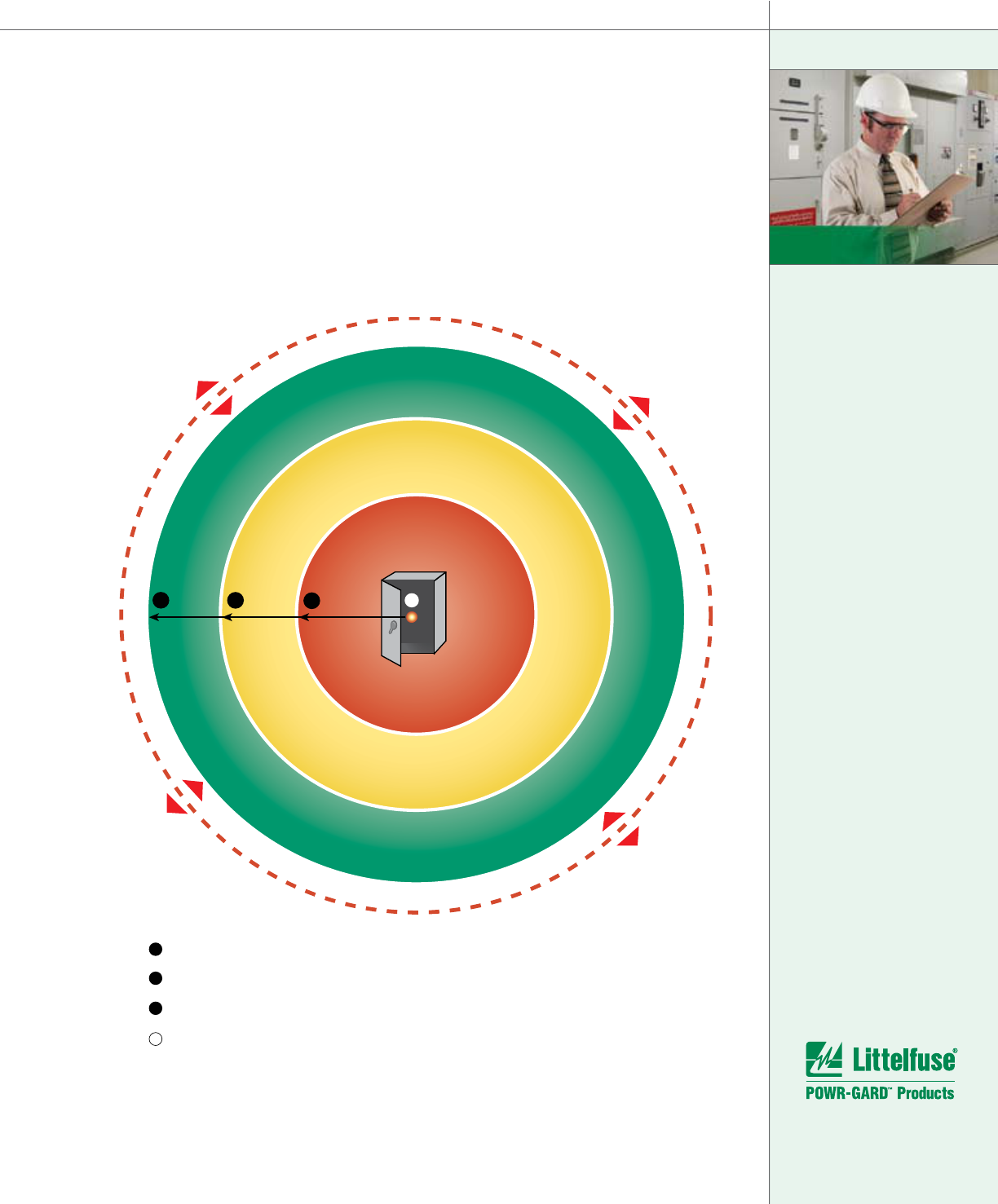
Shock protection boundaries are based on
system voltage and whether the exposed
energized components are fixed or movable.
NFPA 70E Table 130.2(C) defines these
boundary distances for nominal phase-to-
phase system voltages from 50 Volts to 800kV.
Approach Boundary distances may range from
an inch to several feet. Please refer to NFPA
70E Table 130.2(C) for more information.
In summary, a Shock Hazard Analysis is
performed to reduce the potential for direct
shock. It will establish shock protection
boundaries and determine PPE required for
protecting workers against shock hazards.
Completing a shock
hazard analysis
establishes the
system voltage,
shock protection
boundaries and type
of personal protec-
tion equipment
required to protect
workers against
shock hazards.
33
F
l
a
s
h
P
r
o
t
e
c
t
i
o
n
B
o
u
n
d
a
r
y
3
3
1
1
A
A
2
2
Limited Approach Boundary
Restricted Approach Boundary
Prohibited Approach Boundary
Energized Part
Figure 9
Shock Protection Boundaries
For more information:
800-TEC-FUSE
www.littelfuse.com
Flash Hazard Analysis
A complete electrical hazard analysis must also
contain a Flash Hazard Analysis. NFPA 70E Article
130.3 requires this analysis to be performed:
“A Flash Hazard Analysis
shall be done in order to protect
personnel from the possibility of being
injured by an Arc-Flash. The analysis
shall determine the Flash Protection
Boundary and the personal protective
equipment that people within the Flash
Protection Boundary shall use.”
1
The analysis requires the available fault current
to be calculated and documented at every
point in the electrical system. This includes all
components contained in the electrical system.
The end result of this research will be an accurate,
documented one-line diagram, which will provide
the data for a short circuit analysis, and the other
calculations that determine the Flash Protection
Boundary and required level of PPE. In part,
Arc-Flash hazard calculations are based on the
available fault current and the opening time of
overcurrent protective devices. NFPA 70E has also
assigned Hazard Risk Categories based on the
estimated incident energy (typically expressed in
cal/cm²), from an Arc-Flash.
The Flash Protection Boundary (FPB)
The Flash Protection Boundary is the
distance in feet (D
C
) from a given arc
source that will produce a second-
degree burn on exposed bare skin.
Unlike the Shock Hazard Protection Boundaries
that are based solely on system voltage, the
Flash Protection Boundary is not fixed. In order
to determine the potential Arc-Flash hazard,
Flash Protection Boundaries must be calculated
1. Reprinted with permission from NFPA 70E-2004, Standard for
Electrical Safety in the Workplace, Copyright ® 2004, National Fire
Protection Association, Quincy, MA. This reprinted material is not the
complete and official position of the NFPA on the referenced subject,
which is represented only by the standard in its entirety.
at every point where service on energized
equipment, devices, or conductors may be
required. The discussion and examples that
follow are intended to introduce readers to the
required data and some of the methods for
performing an electrical flash hazard analysis at
600 volts and below. Readers are cautioned that
calculations for systems with different voltages,
equipment, devices, and a wider range of fault
currents require the more complete methods
contained in NFPA 70E Article 130 and Annex D.
According to NFPA 70E, the default Flash
Protection Boundary is four feet (48”) based
on an OCPD clearing time of 6 cycles (0.1
sec) and an available fault current of 50 kA
or other combinations not exceeding 5,000-
ampere seconds. For other conditions or
under engineering supervision, calculations
are permitted to determine the Flash
Protection Boundary. Complete formulas
for varying conditions are given in NFPA
70E Article 130 and NFPA 70E Annex D.
The following data is required to
complete the Flash Hazards Analysis:
Up-to-date one-line circuit diagram
of the electrical distribution system
Available fault current from
the utility or generator
Maximum available bolted fault
currents at each location
Minimum self-sustaining
arcing current at each location
Clearing times of all
overcurrent protective devices
As power is distributed throughout your facility, it
is important to remember that although voltage
levels may be higher at the service entrance,
secondary power distribution transformers can
produce much higher current levels and Arc-
Flash energy levels. Power utilities should be
consulted regularly to establish the maximum
available fault current at the service entrance
location of your building. Hand calculations or
•
•
•
•
•
ELECTRICAL HAZARD ANALYSIS
In part, Arc-Flash
hazard calcula-
tions are based on
the available fault
current and the
opening time of
overcurrent protec-
tive devices.
34

commercial software can be used to estimate the
maximum available short circuit current at every
access point in your electrical system.
Arc-Flash Calculations
If the maximum available fault current at a
particular location is known, then an analysis of the
upstream overcurrent protective device (OCPD)
will determine how fast the device will clear the
circuit at the fault current. If these two factors
are known, the amount of incident energy and
the Flash Protection Boundary can be calculated.
The Flash Protection Boundary (D
c
) measured
in feet is based on the bolted fault mega volt-
amperes (MVA
bf
) and the clearing time (t) of
the OCPD. If the bolted fault current (I
sc
) is not
known, it can be calculated based on the MVA
rating and impedance of the source transformer.
An alternate method of determining the Flash
Protection Boundary based on the MVA rating of
a source transformer with an impedance of 5%
and the clearing time (t) of the OCPD is supplied
in NFPA 70E. Table A provides a basic formula
for calculating the Flash Protection Boundary.
Multiple methods are also provided in NFPA
70E Annex D for estimating incident energy
under varying conditions. The results can vary
drastically depending on the specific system
parameters. An arcing fault will also produce very
different incident energy levels depending on if
the arc is in open air or confined in a cubic box.
The formula in Table B estimates the incident
energy for a fault occurring in a 20 inch cubic
box with one side open. This estimate simulates
the potential effect of an arc-flash while working
in equipment and switchgear enclosures.
During arcing faults the arc impedance
(resistance) reduces arc current. Because
the opening times of OCPD increase as the
short-circuit current (I
sc
) decreases, lower
arc fault currents may greatly increase the
total arc energy. Studies have shown that
the minimum self-sustainable arc in 480 volt
systems is 38% of the available bolted fault
current. Because of the increased time at this
reduced fault level, the incident energy may be
higher than under bolted fault conditions. Each
point in the system needs to be evaluated for
both maximum and minimum fault currents.
NFPA 70E refers
to three methods
to determine
the incident
energy or Hazard
Risk Category.
35
D
C
= FPB distance in ft. from the Arc
MVA
bf
= Available bolted fault MVA in mega volt-amps at point of fault
MVA = Transformer capacity in mega volt-amps
t = Clearing time of overcurrent protective device in seconds
D
c
= [2.65 x MVA
bf
x t]
½
OR D
c
= [53 x MVA x t]
½
Table A
Note:
The formula in Table B only applies to systems where the available
short circuit current is in the range of 16kA to 50kA.
E
MB
= Maximum 20 in. cubic box incident energy
D
B
= Distance from arc electrodes, (usually 18 in.)
t
A
= Arc duration, seconds
F = Bolted fault current in kA
E
MB
= 1038.7 D
B
-1.4738
t
A
[0.0093F
2
-0.3453F + 5.9675] cal/cm
2
Table B

ELECTRICAL HAZARD ANALYSIS
36
For more information:
800-TEC-FUSE
www.littelfuse.com
Arc-Flash Hazard Calculation Examples
The following examples break down the
calculations and compare the Hazard Risk
Category (HRC), Incident Energy (cal/cm²), Flash
Protection Boundary (FPB) and PPE (Personal
Protective Equipment) required to work on an
energized 480V system protected by either
2500 Amp Class L fuses or a 2500 Amp low
voltage power circuit breaker.
Example 1
Calculation for energized work in the
transformer metering section of a 2000 kVA
substation. Transformer secondary
protected with current-limiting fuses.
V A
FUSE:
Littelfuse KLPC2500
CLEARING TIME:
0.01 sec @ 43.7kA
2000 kVA
4160V/480V
5.5%Z
Example 2
Calculation for energized work in the
transformer metering section of a 2000 kVA
substation. Transformer secondary
protected with a circuit breaker.
V A
CIRCUIT BREAKER
CLEARING TIME:
0.083 sec @ 43.7 kA
2000 kVA
4160V/480V
5.5%Z
The following
example illustrates
the difference in
incident energy
between a current-
limiting fuse and a
circuit breaker.
Refer to Annex D for Step by step instructions of this example.

Example 1 (continued)
NFPA 70E Article 130.3 (A)
Flash Protection Boundary Distance
Calculate MVA
bf
:
Note: 2000 kVA = 2 MVA
MVA
bf
=
100
×
MVA
=
100
×
2
%Z 5.5
MVA
bf
= 36.4 MVA
Calculate D
C
:
t = 0.01 sec
D
C
= (2.65 × MVA
bf
× t)
D
C
= (2.65 × 36.4 × 0.01) = 0.98 ft ≅ 12 inches
NFPA 70E Annex D.6.2(a)
Incident Energy Exposure
Calculate I
sc
:
I
sc
=
MVA × 10
6
×
100
3 × V
AC
%Z
I
sc
=
2 × 10
6
×
100
= 43,738 Amps
3 × 480 5.5
Calculate F:
F =
Isc
=
43,738 A
= 43.7 kA
1000 1000
Calculate E
MB
:
For this calculation, D
B
= 18 inches
E
MB
= 1038.7 × D
B
-1.4738
× t
a
× (0.0093 F
2
– 0.3453 F + 5.9675)
E
MB
= 1038.7 × (18)
–1.4738
× (.01) × [0.0093 (43.7)
2
– 0.3453 (43.7)
+5.9675]
E
MB
= 1.27 cal/cm
2
Example 2 (continued)
NFPA 70E Article 130.3 (A)
Flash Protection Boundary Distance
Calculate MVA
bf
:
Note: 2000 kVA = 2 MVA
MVA
bf
=
100
×
MVA
=
100
×
2
%Z 5.5
MVA
bf
= 36.4 MVA
Calculate D
C
:
t = 0.083 sec
D
C
= (2.65 × MVA
bf
× t)
D
C
= (2.65 × 36.4 × 0.083) = 2.83 ft ≅ 34 inches
NFPA 70E Annex D.6.2(a)
Incident Energy Exposure
Calculate I
sc
:
I
sc
=
MVA × 10
6
×
100
3 × V
AC
%Z
I
sc
=
2 × 10
6
×
100
= 43,738 Amps
3 × 480 5.5
Calculate F:
F =
Isc
=
43,738 A
= 43.7 kA
1000 1000
Calculate E
MB
:
For this calculation, D
B
= 18 inches
E
MB
= 1038.7 × D
B
-1.4738
× t
a
× (0.0093 F
2
– 0.3453 F + 5.9675)
E
MB
= 1038.7 × (18)
–1.4738
× (.083) × [0.0093 (43.7)
2
– 0.3453 (43.7)
+ 5.9675]
E
MB
= 10.54 cal/cm
2
In this example,
the incident en-
ergy for a current-
limiting fuse is
eight
times
lower
than the incident
energy for a
circuit breaker.
37
In this example the incident energy is much less when
a current-limiting fuse is used to provide protection.

For more information:
800-TEC-FUSE
www.littelfuse.com
Example Results Comparison
As the examples show, the Flash Protection
Boundary, Incident Energy, and Hazard Risk
Category can vary greatly depending on the
overcurrent protective device being used. In
this particular comparison, the required level of
PPE would also be quite different between the
fuse and circuit breaker. The above calculations
can also be performed using commercially
available software programs. Refer to Annex D
of this handbook for more details on the steps
required to complete the hand calculations.
IEEE 1584 Arc-Flash Hazard Calculation
The Institute of Electrical and Electronic
Engineers (IEEE) publishes the IEEE 1584
“Guide for Performing Arc-Flash Hazard
Calculations.” It contains detailed methods and
data that can be used to calculate Arc-Flash
Hazards for the simplest to the most complex
systems. The Petroleum and Chemical Industry
committee of the IEEE spent many years
developing these methods. They are based on
empirical testing of Class RK1 and Class L fuses,
Low Voltage Molded Case Circuit Breakers,
Insulated Case Circuit Breakers and Low Voltage
Power Circuit Breakers as well as theoretical
modeling. Included in 1584 are spreadsheet
programs that simplify the calculation of
incident energy and flash-protection boundaries.
IEEE 1584 does not address the Safety-
related Work Pratices in the same manner as
NFPA 70E. IEEE 1584 concerns itself primarily
with performing the calculations that may
be necessary to determine safe practices.
The calculation methods in Annex D of
NFPA 70E are based on IEEE 1584 but do
not contain all the data or descriptions of
how these methods were developed. IEEE
1584 outlines 9 steps necessary to properly
perform an Arc-Flash hazard calculation.
Step 1
Collect the system and installation data
Depending on whether you are doing a
complete site analysis or looking at one
individual portion, this step can take a few
minutes or several weeks to perform. Begin
by reviewing the latest up-to-date single line
diagram(s) of the equipment or system you
are analyzing. If single line diagrams are not
available, you must create them. The utility
can provide you with the available fault MVA
and X/R ratio at the entrance to your facility.
If you generate your own electricity, or if you
have emergency or standby generators and
large motors, a more detailed analysis must be
performed. In order to calculate the bolted fault
current available at the point of your application,
you must record on your one line diagram all
transformers and their ratings, circuit breakers
or fusible distribution circuits and their ratings,
MCC’s, and all other equipment between the
power source and the area you are concerned
with. Next, you must record the size, type,
length, and number of cables or busbars, etc.
used between the utility and the distribution and
control equipment being analyzed. The type of
conduit or raceway must also be recorded. All
transformer data must be recorded including
MVA ratings and impedance, and all overcurrent
protective devices must be identified with their
specific characteristics or trip ratings recorded.
ELECTRICAL HAZARD ANALYSIS
According to the
previous example
the required level
of PPE needed
while working
on the equipment
protected by
the circuit breaker
would be much
greater than the
level of PPE needed
while working on
the equipment pro-
tected by the fuse.
38
DATA EX. 1 - FUSE EX. 2 - CIRCUIT BREAKER

Step 2
Determine the system modes of operation
Most installations have only one mode of
operation with one utility connection. However,
larger industrial or commercial buildings or
manufacturing plants may have two or more
utility feeders with tie switching of two or
more transformers, or co-generators running
in parallel. Each mode can be very complex
and require a detailed hazard analysis.
Step 3
Determine the bolted fault currents
You can perform hand calculations or use
commercially available software programs such
as the Littelfuse EDR software to calculate the
bolted fault currents at all points between the
utility and the distribution or control equipment
you are analyzing. It will be necessary to plug
in all of the data you have recorded about the
transformers, cable sizes and lengths, and
type of conduit, etc. used in each installation
to determine the bolted fault currents.
Step 4
Determine the arc fault currents
After determining the bolted fault currents, IEEE
1584 provides a formula to calculate the predicted
arc fault current due to typical arc impedance
and other factors. The predicted arc fault current
for system voltages under 1kV depends on the
bolted fault current, system voltage, arc gap,
and whether the arc would most likely occur in
the open air or in an enclosed box configuration.
Step 5
Find the protective device characteristics and
the duration of the arcs
From the data collected in Step 1 and the
predicted arc fault current determined in Step
4, the next step is to establish the total clearing
time of the overcurrent protective device
immediately on the LINE side of the equipment
you are analyzing. If the fuse manufacturer
or circuit breaker manufacturer publishes
maximum and minimum clearing times, it is
important to use the maximum clearing time
possible for the predicted arc fault current.
NOTE: This step can be omitted if the
overcurrent protective devices are those
already tested and listed in the IEEE 1584
document. See Section 4.6 of IEEE 1584.
Step 6
Document the system voltages and classes
of equipment
Make sure you document the system voltages
and class of equipment such as 15kV switchgear,
5kV switchgear, low-voltage switchgear, low-
voltage MCCs and panelboards, or cable runs.
Step 7
Select the working distances
IEEE 1584 has established three typical working
distances for different classes of equipment.
As previously discussed, incident energy
calculations and Hazard Risk Categories will
depend on the working distances selected.
Step 8
Determine the incident energy for
all equipment
You can use formulas included in the IEEE 1584
document or commercially available software
to calculate the incident energy possible in
cal/cm
2
at the working distance selected.
Step 9
Determine the flash protection boundary
for all equipment
The formulas given within IEEE 1584 can
IEEE 1584 is
one method
of determining
incident energy
and Flash Protection
Boundaries (FPB).
Another method
will be to use NFPA
70E equations and
calculations.
39

be used to determine the distance from
the arc at which the onset of a second-
degree burn will occur to unprotected
skin. This distance must be established
and will vary based on system parameters.
Software programs automatically calculate
the distance based on the arc fault current,
system voltage, arc gap, and arc duration.
If the overcurrent protective devices (OCPD)
are something other than those covered
by IEEE 1584, or if the voltage levels and
short circuit currents exceed the IEEE 1584
limitations, then the opening times of
the overcurrent protective devices must
be analyzed and the corresponding Flash
Protection Boundary and incident energy
must be calculated by another method.
NFPA 70E Table Method
Although NFPA 70E (Article 130.3) requires
a Flash Hazard Analysis, it also provides an
alternate method for determining Hazard
Risk Categories and required PPE. This is
commonly called the “Table Method” and
is based on various tasks to be performed
on energized equipment (see NFPA 70E
Table 130.(C)(9)(a)). The Table Method may
be used in lieu of a complete Flash Hazard
Analysis in some cases. However, a complete
analysis provides more accurate results.
Caution is advised when using the Table
Method. All footnotes listed at the end of
NFPA 70E Table 130.7(C)(9)(a) and in any
applicable Tentative Interim Amendments
must be observed and all prescribed conditions
verified. If a task is not listed in NFPA 70E
Table 130.7(C)(9)(a) or cannot be verified,
then NFPA 70E leaves no other alternative
but to do a complete hazard risk assessment
using one of the other calculation methods.
Steps Required to Use the NFPA 70E
Table Method
Step 1
Once the equipment is identified where work
is to be performed, review the up-to-date one
line drawing for information about the available
short circuit current and other details about
the location of the equipment. If the one line
drawing is not up to date or the available short
circuit is not known, it must be determined.
Step 2
Consult NFPA 70E Table 130.7(C)(9)(a) and find
the task to be performed. If the desired task to
be performed is not listed, the Table Method
cannot be used and a complete Flash Hazard
Analysis is required.
Step 3
Once you find your task in the table, identify the
Hazard Risk Category and determine if voltage
rated gloves or tools are required.
Step 4
Verify that the conditions stated in the footnotes
for NFPA 70E Table 130.7(C)(9)(a), and any
Tentative Interim Amendments such as those
stated in NFPA 70E, are applicable to the task.
Step 5
Using NFPA 70E Tables 130.7(C)(10-11) and
the corresponding notes in Table 130.7(C)(9)(a),
identify the required PPE for the task.
Step 6
The NFPA 70E Table Method does not provide
the Flash Protection Boundary, but it must be
determined. For systems 600V and below,
NFPA 70E defines the FPB as 4 feet. See NFPA
70E for more information on calculating the FPB.
ELECTRICAL HAZARD ANALYSIS
The Table Method
may be used in
lieu of a complete
Flash Hazard
Analysis. However,
a complete analysis
will provide more
accurate results.
40
For more information:
800-TEC-FUSE
www.littelfuse.com

Whether calculations are made or NFPA 70E
Table 130.7(C)(9)(a) is used, the results of an
Electrical Hazard Analysis (Shock and Flash
Hazard Analysis) will determine the following:
The Limited Approach Boundary
The Restricted Approach Boundary
The Prohibited Approach Boundary
Incident Energy possible at
each location
Flash Protection Boundary
Hazard Risk Category
PPE required to work on
energized equipment
•
•
•
•
•
•
•
41
OSHA regulations
must be followed
to perform a hazard
assessment, and
to determine the
PPE required for
properly protecting
electrical workers.
41
For more information:
800-TEC-FUSE
www.littelfuse.com
NFPA 70E guidelines and practices are generally
considered the “How to” of conforming to the
OSHA regulations when performing a hazard
assessment, and determining the required PPE.
There are many practices that will help reduce
Arc-Flash and other electrical hazards while
conforming to OSHA and NFPA 70E regulations
and guidelines. Circuit designers and electrical
maintenance engineers should carefully consider
each of the following recommendations:
1. Design a safer system.
2. Use and upgrade to current-limiting
overcurrent protective devices.
3. Implement an Electrical Safety Program.
4. Observe safe work practices.
5. Use Personal Protective Equipment (PPE).
6. Use Warning Labels.
7. Use an Energized Electrical Work Permit.
8. Avoid hazards of improperly selected or
maintained overcurrent protective devices.
9. Achieve or Increase Selective Coordination.
1. Design a safer system.
Goals
When designing a safer system the following
goals and factors should be considered:
Provide maximum protection to
personnel, equipment, and property.
Meet all applicable code require-
ments (OSHA, NFPA, Building
and Insurance codes, etc.)
Utilize current-limiting overcurrent
protective devices to minimize
Arc-Flash hazards.
Utilize “touch-safe” components
to minimize exposure to energized
components
Utilize fuses with blown fuse
indication to minimize exposure
to energized components while
trouble-shooting the circuit.
Provide selective coordination
(only the area where the
fault occurs is shut-off)
Provide a system that is safe to
service and maintain.
•
•
•
•
•
•
•
Estimates show that
10 Arc-Flash
incidents
occur every day
in the U.S.
42
Minimizing Arc-Flash and Other Electrical Hazards

System Requirements
Once the goals for your system are established,
the selection of the overcurrent protective
devices that best meet those goals can be
determined. What is the best choice for your
application; fuses or circuit breakers? Fuses offer
many safety and performance advantages over
circuit breakers. Factors to consider include:
System voltage
Voltage ratings for fuses are stan-
dardized at 250, 300, and 600
volts. In comparison, some circuit
breakers are rated for dual volt-
ages and are often mis-applied.
Interrupting rating
Most fuses have standard ratings of
200kA at full rated voltage. Circuit
breaker interrupting ratings may range
from 10kA to 100kA, but the interrupt-
ing ratings of many breakers vary with
system voltage and type of trip unit.
System changes resulting in increased
available fault current
If your facility grows or the utility makes
changes, fault currents have been
known to more than double. Interrupting
ratings of overcurrent protective devices
must be regularly reviewed to insure
the device will still protect the system.
Load current characteristics
Inductive loads such as motors and
transformers and even large incandes-
cent lamps have large inrush currents
that require circuit breakers to be
oversized so that overload protection is
sacrificed. Properly selected time-delay
fuses can be sized close to load currents
and will offer better overload protection.
•
•
•
•
Current-limitation
Current-limiting OCPDs reduce
damage from major faults. Often
devices or equipment can be easily
repaired rather than face time-con-
suming and costly replacement.
Are your sensitive control devices such as
motor starters truly protected?
After a fault, will the units be usable or will
they require replacement? Only current-
limiting fuses can provide Type 2 Protec-
tion. That means you are up and running
once the cause of the fault is removed.
2. Use and upgrade to current-limiting
overcurrent protective devices.
The incident energy from an Arc-Flash depends
on the magnitude of the current and the time it
is allowed to flow. Within their current-limiting
range, current-limiting devices reduce the peak
fault current. Current-limiting fuses have much
faster clearing times when operating within
their current-limiting range than standard circuit
breakers. The faster the overcurrent protective
device clears the fault, the lower the I²t and
incident energy will be. If current-limiting fuses
are used, the incident energy and the Hazard
Risk Category may be reduced significantly.
Upgrade to Class RK1 or Class J current-
limiting fuses
One of the quickest and easiest ways to reduce
potential incident energy, lower the Hazard Risk
Categories and reduce the required PPE, is to
replace UL Class H, K5 or Class RK5 fuses with
current-limiting UL Class RK1 or Class J fuses.
Upgrading to time-delay Class J fuses affords the
best solution by providing the best current limitation
while assuring non-interchangeability with non-
current-limiting fuses. If an equipment manufacturer
•
•
Upgrading to
Class RK1 or Class J
current- limiting
fuses is the
easiest way to:
Reduce potential
Arc-Flash hazards
Reduce Hazard
Risk Categories
Reduce the
amount of
required PPE
•
•
•
43
For more information:
800-TEC-FUSE
www.littelfuse.com
has specified a non-time delay fuse, standard Class
J fuses are available. If your equipment already has
UL Class H fuse clips, it is very easy to replace the
Class H or K5 fuses being used with Class RK1
fuses. For a given current and voltage rating, UL
Class H, K5, RK5, and RK1 fuses are the same
physical size, therefore, it is easy and strongly
recommended to upgrade to better fuse protection.
To assure that only current-limiting fuses are used,
consider changing to Class J clips or to rejection
type clips that will accept only Class R fuses.
Current-limiting fuses that also offer blown
fuse indication such as the Littelfuse Class
J JTD_ID and Class RK1 LLSRK_ID can help
reduce exposure to electrical hazards. The
unique blown fuse indicator decreases
downtime by immediately indicating the opened
circuit and maximizes safety by minimizing
exposure to energized components when
trouble-shooting. Replacing non-current-
limiting fuses with Littelfuse current-limiting
Indicator
®
fuses can significantly reduce the:
Incident energy from an Arc-Flash
The Hazard Risk Category
The level and type of PPE necessary
Trouble-shooting and downtime.
•
•
•
•
MINIMIZING ARC-FLASH AND OTHER ELECTRICAL HAZARDS
Current-limiting fuses
that also offer blown
fuse indication such
as the Littelfuse Class
RK1 LLSRK_ID series
can help:
reduce exposure to
electrical hazards
decrease downtime
maximize safety
•
•
•
44
* Consult Article 430 of the NEC
®
when substituting for loads with motors, or call 800-TEC-FUSE
Class L
KLPC
KLPC
KLLU
KRPC
KLU
KTU
A4BQ
A4BY
A4BT
LCL
LCU
Class RK1
(600 Volts)
LLSRK_ID
FLSR
FLSR_ID
NLS*
RLS*
LLSRK
KLSR*
FRSR
NOS*
RES*
LPSRK
KTSR*
TRS
OTS*
RFS*
A6DR
A6KR*
GF6B
ECSR
LESRK
KOS*
ERS*
Class RK1
(250 Volts)
LLNRK
FLNR
NLN*
RLN*
KLNR*
FRNR
NON*
REN*
LPNRK
KTNR*
TR
OT*
RF*
A2DR
A2KR*
GF6A
ECNR
LENRK*
KON*
ERN*
Class J
JTD_ID
JTD
JLS*
LPJ
JHC
JKS*
AJT
A4J*
JDL
JFL*
Class CC
CCMR
FLM
FLQ
KLDR
KLK
BLS
BLF
BLN
KLKR
LPCC
FNM
FNQ
FNQR
KTKR
KTK
BBS
BAF
BAN
ATDR
TRM
ATQ
ATQR
ATMR
SBS
OTM
ATM
EDCC
MEN
MEQ
HCTR
HCLR
MCL
EBS
MOL
You Should Use This Fuse....
If You Have This Fuse....
Use the table below to consolidate your
fuse inventory and eliminate unsafe or
unnecessary fuses.

3. Implement an Electrical Safety Program.
Electrical Safety Programs protect both
employees and employers and provide goals,
procedures and work practices to insure safety.
NFPA 70E Article 110.7 requires employers
to establish an Electrical Safety Program that
must be documented and include the minimum
following components:
Scope of the Program
Company Philosophy
Responsibilities
Establishment of a Safety
Team or Committee
Written Procedures
Work Instructions
Identification of Industry Codes
& Standards to be adhered to
Establishment of a Documented
Training Program
Establishment of Assessment
and Audit Requirements
Company Policies and Enforcement
Increased safety will be possible with the
implementation and vigorous enforcement of
a well-designed and documented Electrical
Safety Program. These programs should
be in accordance with all OSHA regulations
and nationally recognized safety standards
such as NFPA 70E and NEC
®
. For more
information on establishing an Electrical
Safety Program, refer to NFPA 70E Annex E
or NFPA’s Electrical Safety Program Book.
4. Observe safe work practices
Maintenance
Safe maintenance practices and procedures
include properly training employees in the
knowledge of the equipment and tools
necessary for maintenance and repair. NFPA
70E states that employees “shall be trained
in and familiar with the specific maintenance
procedures and tests required.” Test equipment
•
•
•
•
•
•
•
•
•
•
as well as hand tools are often overlooked and
must be insulated and rated for the voltage
of the circuits where they will be used. All
tools and equipment used for maintenance
must also be periodically inspected to ensure
they are not damaged (i.e. torn insulation)
and are still in good working condition.
Disconnect Operation
Operating a damaged disconnect switch,
whether it’s a fusible switch or circuit breaker,
can be dangerous. Serious injury could occur if
someone is standing in front of a faulty switch
or circuit breaker while opening or closing
the device. If the handle is on the right hand
side of the device, stand to the right, use
your left hand to grasp the handle, turn your
face away and then operate it. If the handle
is on the left side, reverse the procedure.
Use special caution while operating circuit
breakers. If closed into a fault, circuit breakers
will trip, drawing an internal arc. The gases
from the arc are very hot, and vent through
openings in the breaker. These hot gases often
vent around the handle and can cause burns
unless proper protective equipment is used.
Proper Service or Repair of All
Equipment or Devices
a) Locate the equipment where work is to be
performed. If equipment is running, follow
manufacturer’s shutdown procedures being
sure that all unit switches are off. Do not
open any enclosures. Determine if there is
adequate working space and that it is clear
of obstructions.
b) Locate all disconnecting means providing
power to the equipment, including all
sources of emergency, alternate, and control
power. This must include discharging
capacitors and other sources of stored
energy. Turn all disconnecting devices to the
OFF position and apply lockout/tagout
devices as required by OSHA and the
company’s Electrical Safety Program.
c) While wearing proper personal protective
equipment, open the enclosure door or
access panels. Test the voltage meter to be
The implementation
and enforcement
of a well-designed
Electrical Safety
Program in accor-
dance with OSHA
and NFPA 70E will
increase safety in
your facility.
45

MINIMIZING ARC-FLASH AND OTHER ELECTRICAL HAZARDS
46
For more information:
800-TEC-FUSE
www.littelfuse.com
used on a known energized source to be
sure it is working properly. Test all exposed
wires, contacts and other components likely
to be energized insuring that the equipment
is in an electrically safe work condition.
Equipment containing fuses
d) If it is suspected there is one or more
opened fuses, remove fuses from the circuit
using the proper size fuse puller.
Note: The use of Littelfuse Indicator
®
Fuses will minimize time required to
locate opened fuses, and help avoid
mixing them with good fuses.
e) Place fuses on a non-conductive surface and
measure fuse resistance across the ends
(endcaps/blades) of the fuse with a meter. If
the fuses have knife blades be sure to test
from blade to blade since some types of
fuses have insulated end caps and will give a
false reading. High resistance indicates that
the fuse may be open.
f) Investigate the circuit to identify the cause of
any blown fuses. Look for loose connections
or signs of overheating. Correct the problem.
g) Verify the proper fuse class, voltage, ampere,
and interrupting ratings before installing
replacement fuses. (Caution: because fuse
characteristics may vary between manufac-
turers and fuse classes, fuses should be of
the same manufacturer and class for each
application.)
h) Examine fuse clips or mountings for signs of
corrosion, overheating, or loss of tension.
Service if necessary. Install the replacement
fuse with the proper size fuse puller.
Equipment containing circuit breakers
i) After following steps 1 through 3 above,
look for circuit breakers and examine to
see if any are tripped. Examine the circuit
breaker(s) to see if the case or surround-
ing area shows signs of severe venting
indicating a serious fault.
j) Investigate the circuit for the causes of
circuit breaker tripping. Correct the problem.
If breaker is protecting motor starters,
especially IEC or single-purpose type, test
the motor starters to be sure they are still
functional. If the motor starters have
heaters (resistance coils) in the overloads,
test the resistance across the heaters to
insure they are still functional.
k) Test resistance across the poles of the
open circuit breaker to be sure all poles are
open and there are no shorts between
poles. Close the circuit breaker and
measure resistance across the closed
poles to insure resistances are within
tolerances and are equal from pole to pole.
Placing equipment in service
l) Following manufacturer’s instructions, close
all internal switches and circuit breakers and
other procedures necessary for start-up.
m) Close enclosure door(s) and access panels
and check the area for other personnel.
Remove lockout/tagout devices following
OSHA and safety program procedures.
n) Restore power standing to the side of the
switch enclosures.
o) Restart equipment following manufacturer’s
instructions and exercising caution until
satisfactory operation is insured.
Lockout/tagout Procedures
OSHA requires that energy sources to
machines or equipment must be turned off and
It is estimated that
Lockout/Tagout
prevents about
120 fatalities and
50,000 workday
injuries annually.
Source:
Occupational Safety and Health Administration

disconnected isolating them from the energy
source. The isolating or disconnecting means
must be either locked or tagged with a warning
label. While lockout is the more reliable and
preferred method, OSHA accepts tagout to
be a suitable replacement in limited situations.
It is estimated that Lockout/tagout prevents
about 120 fatalities and 50,000 workday injuries
annually. Approximately 39 million workers are
protected by Lockout/tagout practices. Failure to
comply with Lockout/tagout safety regulations
is frequently one of the top five OSHA violations.
In 2004 alone, there were over 4,300 violations
cited by OSHA. NFPA 70E Article 120 contains
detailed instructions for lockout/tagout and placing
equipment in an Electrically Safe Work Condition.
Application of Lockout/tagout Devices
a) Make necessary preparations
for shutdown
b) Shut down the machine or equipment
c) Turn OFF (open) the energy-
isolating device (fuse/circuit breaker)
d) Apply the lockout or tagout device
e) Render safe all stored or
residual energy
f) Verify the isolation and deenergiza-
tion of the machine or equipment
Removal of Lockout/tagout Devices
a) Inspect the work area to ensure that non-
essential items have been removed and
that machine or equipment components
are intact and capable of operating
properly. Especially look for tools or
pieces of conductors that may not have
been removed.
b) Check the area around the machine
or equipment to ensure that all
employees have been safely
positioned or removed.
c) Make sure that only the employees who
attached the locks or tags are the ones
that are removing them.
d) After removing locks or tags, notify
affected employees before starting
equipment or machines.
5. Use Personal Protective Equipment (PPE)
The proper selection and use of Personal
Protective Equipment will significantly reduce
the risk of Arc-Flash and other electrical
hazards to personnel working on energized
equipment. OSHA Part 1910.335 (a) states:
“…Employees working in areas where
there are potential electrical hazards
shall be provided with, and shall
use, electrical protective equipment
that is appropriate for the specific
parts of the body to be protected
and for the work to be performed.”
A variety of PPE is available from numerous
manufacturers. The most common
types of protective gear include:
Nonconductive flame-resis-
tant head, face, and chin pro-
tection (hard hats, full face
shields, switching hoods, etc.)
Eye protection (face shields,
safety glasses, goggles)
Body protection resistant to
flash flame (shirts, pants,
jackets, coveralls)
Hand and arms protection
(insulating gloves and sleeves
with leather protectors)
Foot and leg protection (insulated
leg and footwear)
Insulating blankets or mats
•
•
•
•
•
•
The proper
selection and use
of PPE will greatly
reduce the risk
of Arc-Flash and
other electrical
hazards.
47

Selection of PPE is dependant on the task to be
performed. NFPA 70E Tables 130.7(C)(9), (10),
and (11) provide guidance for the selection of
personal protective equipment to be used for
specific tasks and hazard levels. The Table of PPE
requirements below provides typical clothing
requirements for Hazard Risk Categories from
0 through 4. Note: Hazard Risk Category 0 still
requires some level of protective clothing or
equipment. Manufacturers have also developed
tables and selection guides based on NFPA 70E
recommendations. It is important to note that
the level of PPE recommended by NFPA 70E is:
“intended to protect a person from arc-flash and
shock hazards”. Even with PPE, some arc-flash
conditions may result in burns to the skin or include
arc blast pressures, toxic vapors, and propelled
particles and materials. PPE that is selected should
be rated for, or greater than, the minimum Arc-Flash
rating required for each Hazard Risk Category.
Common Personal Protective
Equipment Terms and Definitions
Arc Thermal Performance
Exposure Value (ATPV)
The incident energy level (in cal/cm²) that can
cause the onset of a second-degree burn
as defined in ASTM F 1959 Standard Test
Method for Determining the Arc Thermal
Performance Value of Materials for Clothing.
Personal Protective Equipment will be labeled
with a calorie rating (Example: 11 cal/cm²).
V-rated
Tools and gloves rated and tested
for the line-to-line voltage at the area
where the work is to be performed.
Flame Resistant (FR)
“The property of a material whereby combustion
is prevented, terminated, or inhibited
following the application of a flaming or non-
flaming source of ignition, with or without
susequent removal of the ignition source.”
1
Breakopen Threshold Energy (E
BT
)
The incident energy level which does not
cause flame resistant (FR) fabric breakopen
and does not exceed second-degree burn
criteria, as defined in ASTM F 1959.
Standards such as OSHA 1910.137 also specify
that protective gear must be maintained and
periodically inspected to ensure that it remains in
a safe and reliable condition. NFPA also supports
this in NFPA 70E Articles 130.7(B), 130.7(C)(8) and
130.7(F). NFPA requirements state that PPE should
be inspected before and after each use, and be
repaired, cleaned or laundered according to the
manufacturer’s instructions prior to use. It is also
extremely important to avoid contamination of
PPE material. Contact with grease, solvents, and
flammable liquids may destroy the protection.
1. Reprinted with permission from NFPA 70E, Standard for Electrical
Safety in the Workplace, Quincy, MA: National Fire Protection
Association, 2004. This reprinted material is not the complete and
official position of the NFPA on the referenced subject, which is
represented only by the standard in its entirety.
PPE that is selected
should be rated for,
or greater than, the
minimum Arc-Flash
rating required for
each Hazard
Risk Category.
MINIMIZING ARC-FLASH AND OTHER ELECTRICAL HAZARDS
48
For more information:
800-TEC-FUSE
www.littelfuse.com
Hazard Risk
Category
Required
Minimum
Arc Rating of
PPE (cal/cm
2
)
Typical Protective Clothing Systems
Clothing Description
Minimum
Flash
Protection
Boundary
(in.)
0 N/A
1 layer of non-melting, flammable fabric with weight of at least 4.5 oz/yd
2
6
1 4
1 layer of a FR shirt and FR pants or FR coverall
15
2 8
1 or 2 layers of FR shirt and FR pants with conventional cotton underwear
45
3 25
2 or 3 layers of FR shirt, FR pants plus FR coverall cotton underwear
60
4 40
3 or more layers of FR shirt, FR pants plus multi-layer flash suit
~120
PPE REQUIREMENTS
Derived from NFPA 70E Table 130.7(C)(11)

6. Use Warning Labels.
The National Electrical Code
®
recently recognized
Arc-Flash hazards and developed a warning
label requirement. NEC
®
Article 110.16 states:
“110.16 Flash Protection:
Switchboards, panelboards, industrial
control panels, meter socket enclosures,
and motor control centers that are
in other than dwelling occupancies
and are likely to require examination,
adjustment, servicing, or maintenance
while energized shall be field marked
to warn qualified persons of potential
electric Arc-Flash hazards. The marking
shall be located so as to be clearly
visible to qualified persons before
examination, adjustment, servicing, or
maintenance of the equipment.”
1
While the overall requirement is very
comprehensive, the required label format
can be very generic. However, if a complete
electrical hazard analysis is performed, the
preferred approach would be to include
the Hazard Risk Category, Flash Protection
Boundary, Incident Energy available, level
of PPE required, system voltage, and shock
protection boundaries on labels. See Figures 10
and 11 for examples of typical warning labels:
Minimum Label Requirements
Bus: SERVICE4 05/12/05
42 inches 12 inches 1 inch
1 480 VAC
35 kA
32 inches
2.77 cal/cm
2
Figure 10
1. Reprinted with permission from NFPA 70-2005, National Electrical
Code
®
Copyright © 2004, National Fire Protection Association,
Quincy, MA. This reprinted material is not the complete and official
position of the NFPA on the referenced subject, which is represented
only by the standard in its entirety.
Preferred Label Approach
Bus: SERVICE4 05/12/05
42 inches 12 inches 1 inch
1 480 VAC
35 kA
32 inches
2.77 cal/cm
2
Figure 11
The use of detailed warning labels not only
increases safety, but also minimizes the time
required to identify minimum levels of PPE.
Other types of warning labels should also be
used to include information about proper fuse
replacements, location of disconnects and
other sources of power, etc. Warning labels
can be applied directly to pieces of equipment
or on enclosure doors. Computer programs
and adhesive blank labels make it easy to
create labels for almost every purpose.
7. Use an Energized Electrical Work Permit.
NFPA 70E requires that a detailed written
Energized Electrical Work Permit must
be used and signed by responsible
management whenever work is performed
on live energized equipment.
See Annex C of this handbook for an
example of an Energized Electrical
Work Permit. For additional information
on Energized Electrical Work Permits,
refer to NFPA 70E Article 130.1(A).
The use of detailed
warning labels will
increase safety as
well as minimize
the time required to
identify minimum
levels of PPE.
49

For more information:
800-TEC-FUSE
www.littelfuse.com
8. Avoid Hazards of Improperly Selected or
Maintained Overcurrent Protective Devices.
Whether in the design or maintenance of
an electrical system, hazards exist if the
proper overcurrent device is not selected and
applied. Circuit breakers and other electrical
equipment must be maintained and serviced
regularly to ensure that they will operate
properly when needed. Unfortunately, in many
industries and especially during economic
turndowns, the tendency is to limit or eliminate
regularly scheduled maintenance on circuit
breakers and other electrical equipment.
However, the potential costs associated with
OSHA violations, liability lawsuits, workers
compensation, equipment replacement, and
lost production far exceeds the costs of
regular testing and maintenance of circuit
breakers and other electrical equipment.
OSHA 29 CFR 1910.334(b)(2)
“Reclosing circuits after protective
device operation. After a circuit is
deenergized by a circuit protective
device, the circuit may NOT be
manually reenergized until it has been
determined that the equipment and
circuit can be safely reenergized. The
repetitive manual reclosing of circuit
breakers or reenergizing circuits
through replaced fuses is prohibited.
NOTE:
When it can be determined from the
design of the circuit and the overcurrent
devices involved that the automatic
operation of a device was caused
by an overload rather than a fault
condition, no examination of the circuit
or connected equipment is needed
before the circuit is reenergized.”
In this section of the regulations, OSHA
recognizes the importance of knowing why
the overcurrent protective device has opened.
If the fuse or circuit breaker opened due to
an overload, no examination of the circuit or
connected equipment is necessary. However, if
the overcurrent protective device opened due
to a short circuit fault, catastrophic results can
occur if the fuse or circuit breaker is replaced or
closed on the short circuit before it is corrected.
This is especially important for circuit breakers
and switches because short circuit currents can
permanently damage the equipment to the point
that it will not operate safely when reenergized.
Circuit Breakers
Circuit breakers, like fuses, are rated to safely
interrupt their maximum interrupting current
only once. Molded Case Circuit Breakers
(commonly referred to as MCCB’s) must meet
the requirements of UL489, “Standard for
Safety,” Molded-Case Circuit Breakers, Molded
Case Switches and Circuit Breaker Enclosures.
This standard allows manufacturers to list their
circuit breakers at varying degrees of available
fault currents, current-limiting ability and other
characteristics. They must be applied within
the maximum limitations of their ratings.
Circuit breaker manufacturers typically
recommend that their circuit breakers be cycled
ON and OFF at least once each year to keep
the tripping mechanism from seizing under
certain environmental conditions. Cycling circuit
breakers ON and OFF manually may help keep the
switching mechanism from seizing, but may not
guarantee that the tripping mechanism will operate
properly. Some manufacturers also recommend
that their circuit breakers be periodically tested and
recalibrated under carefully controlled conditions.
When testing time-current characteristics,
recommendations state the circuit breaker
being tested must be at room temperature. This
practice would increase equipment downtime
while the circuit breaker to be tested cools
down after it is removed from service.
The National Electrical Manufacturers Association
(NEMA) has published standard AB 4-2003
entitled, “Guidelines for Inspection and Preventive
Maintenance of Molded Case Circuit Breakers
Used in Commercial and Industrial Applications.”
It deals exclusively with the maintenance and
care of Molded Case Circuit Breakers to provide
reliable protection. The expected lifetime of a
circuit breaker, however, depends on circuit
conditions and its’ environment. Standard AB
4-2003 emphasizes that safe work practices
MINIMIZING ARC-FLASH AND OTHER ELECTRICAL HAZARDS
Circuit breakers trip-
ping mechanisms
could seize up and
not operate properly
if not maintained
to manufacturer’s
specifications.
50

include regular periodic maintenance, and
investigating what caused the circuit breakers to
operate prior to reenergizing the circuit — similar
to OSHA 29 CFR 1910.334(b)(2). There are other
published industry standards for maintenance
of large Air Power Circuit Breakers. Preventive
maintenance of these circuit breakers should be
performed at least annually, and after interruption
of a fault some 20 or more steps are required
before placing the circuit breaker back in service.
The Institute of Electrical and Electronic
Engineers (IEEE) has also published Standard
493-1997, otherwise known as the “Gold Book,”
entitled, Recommended Practice For the Design
Of Reliable Industrial And Commercial Power
Systems. The IEEE studied failure statistics of
typical industrial and commercial electrical
distribution systems and components over
several years prior to 1974 and more recently in
1996. The results of the 1996 study concluded
nearly
1
/
3
of all circuit breakers that failed while in
service could have been avoided if proper
maintenance and testing was performed.
Article 225.3 of NFPA 70E
requires that if a circuit breaker
interrupts a fault at or near its
interrupting rating, it must be inspected
by a trained technician and tested,
repaired or replaced in accordance with
the manufacturer’s specifications.
If proper maintenance and repair is neglected,
circuit breakers may fail to open or open more
slowly than when first calibrated. The IEEE
study noted that circuit breaker failures caused
excessive equipment damage, blackouts,
unexpected repair and replacement costs, lost
production, scrap production, and most
importantly, severe blast and burn injuries to
personnel. Proper care and maintenance of
circuit breakers must be part of any Electrical
Safety Program.
Other common safety hazards involve using
overcurrent protective devices with improper
interrupting ratings. Standard circuit breakers
have relatively low interrupting ratings (typically
10,000 to 100,000 AIC) when compared to
fuses (200,000 AIR). The circuit breaker’s
low interrupting rating may not be an initial
hazard, but as available fault currents rise from
the utility, a dangerous situation is created.
During service upgrades, circuit breakers with
low interrupting capacities may have to be
replaced by higher rated devices or protected
by fuses in order to lower fault currents.
Non-current-limiting fuses
Another potential electrical hazard is the
use of non-current-limiting fuses including
“renewable” fuses. Although fuse standards
and fuse technology have changed greatly,
many older machines and equipment may
contain Class H (one-time or renewable) or
K5 one-time fuses. The continued use of
these fuses especially where available fault
currents exceed their interrupting ratings
can be catastrophic. In addition to being
non-current-limiting, Class H and K5 fuses
have lower interrupting ratings than the Class
R or J fuses. Just like non-current-limiting
circuit breakers, the Class H and K5 fuses
may permit much higher current to flow for a
much longer time, increasing risk to workers
and the equipment. The incident energy of an
Arc-Flash could be deadly to an unsuspecting
worker who is not properly protected.
9. Achieve or Increase Selective Coordination.
When an overcurrent occurs in a system only
the overcurrent protective device immediately
on the line side of the overcurrent should
open. This reduces unnecessary shutdown
of other equipment and simplifies locating
the problem. Such systems are defined as
“selectively coordinated.” Refer to Figure 12.
If a system is not selectively coordinated, a fault
at point A can cause the fuses or circuit breakers
at points B, C, and D to open, needlessly
shutting off power to two or more unaffected
areas. In a selectively coordinated system, a
fault at point A will cause only the fuse or circuit
breaker immediately before the fault to open,
keeping power supplied to the rest of the feeder
and branch circuits throughout the facility.
51

For more information:
800-TEC-FUSE
www.littelfuse.com
MINIMIZING ARC-FLASH AND OTHER ELECTRICAL HAZARDS
Achieving a selec-
tively coordinated
system not only
reduces downtime
and the risk of
Arc-Flash exposure,
but the National
Electrical Code
®
requires it.
52
Feeder circuit breakers or fuses are typically
rated at least twice that of the downstream
devices. An Arc-Flash that opens the upstream
devices means that the total I
2
t heat energy and
consequently, incident energy, is determined by
the largest upstream device. In this situation, the
electrical system is not selectively coordinated,
and the incident energy increases as a result
of the time elapsed before the upstream
overcurrent protective device clears the fault.
Achieving a selectively coordinated system
not only reduces downtime and the risk of
Arc-Flash exposure, but Articles 240.12, 700.27,
701.18 and 620.62 of the National Electrical
Code require it. These code specifications refer
to emergency circuits or potential life saving
circuits such as alarm circuits, emergency
lighting, and elevator circuits. For example,
during an emergency or in a building with an
elevator, an overcurrent on one elevator motor
must not cause the feeder circuit to open all
other elevator circuits, or alarm systems.
It is also unsafe to replace blown fuses with
slightly higher ampere ratings in order to
compensate for nuisance openings. Doing
so will defeat selective coordination and can
dramatically increase the amount of risk to
workers if an Arc-Flash occurs. In order to
decrease downtime and reduce the risk of
Arc-Flash exposure to unsuspecting workers,
it is best to replace non-current-limiting fuses
and circuit breakers with more accurately
rated time-delay current-limiting fuses such as
the Littelfuse Class RK1 LLSRK_ID series.
Electrical safety is important for everyone.
Employees working on electrical systems
are at risk every day, but with the
properly designed overcurrent protection
system, the implementation of safe
work practices and the utilization of the
appropriate PPE, risk can be minimized.
D
D
C C
B
B
A
A
LOAD
#1
Fuse Opens
Circuit Breaker Opens
Fuse Not Opened
Unnecessary
Power Outage
LOAD
#1
Without Selective
Coordination
With Selective
Coordination
LOAD
#2
LOAD
#2
Examples of loads
include: motors,
elevators, lighting, etc.
FAULT FAULT
Legend:
Figure 12
Selective Coordination

53
Electrical Safety Summary
Employees working
on electrical systems
are at risk every day,
but with the properly
designed overcurrent
protection system,
the implementation
of safe work practices
and the utilization
of the appropriate
PPE, risk can be
minimized.
Here is a brief review of some basic
electrical safety concepts.
1) Unless there is a compelling safety
issue such as life-support equipment,
alarm systems, hazardous location
ventilation, or lighting required for
safety, OSHA requires that circuits be
deenergized and the system be placed
in an Electrically Safe Work Condition
before any work is performed.
2) When placing equipment in an
Electrically Safe Work Condition,
always follow proper Lockout/tagout
procedures.
3) An Electrical Hazard Analysis must
be performed on all circuits 50 volts
and higher that may be worked on
while energized.
4) The Hazards must be identified and
warning labels must be applied to all
equipment that may be worked on
while energized.
5) Workers must be trained on the
equipment, hazards and safety
precautions, and be certified as
“qualified” to work on energized
equipment. Training and certification
must be documented.
6) All work performed on energized
equipment must be preceded by a
job briefing and a signed Energized
Electrical Work Permit.
7) When working on or approaching
energized circuits, proper protective
clothing must be worn. The minimum
flame retardant clothing, safety
glasses, and protective gloves and
equipment must meet OSHA and
NFPA 70E guidelines. Protective
insulating blankets and mats are
also used to minimize exposure.
8) Be certain there is adequate lighting
for the tasks to be performed. Por-
table lighting must be fully insulated
so that it will not accidentally cause
short circuits when used near
energized components.
9) Use barricades or barriers to warn
unqualified individuals from entering
the area.
10) Be prepared for the unexpected. Make
sure emergency communications and
trained medical personnel are avail-
able if something goes wrong.
11) Use current-limiting overcurrent
protective devices wherever possible
to reduce the potential electrical
hazards.
Electrical Safety in the workplace can only be
attained when workers and employers diligently
follow OSHA and industry accepted standards
and regulations. It is our sincere hope and desire
that this handbook has been helpful in informing
the reader of the importance of Electrical Safety
while providing methods and information on how
to effectively and safely reduce electrical hazards.

For more information:
800-TEC-FUSE
www.littelfuse.com
A.I.C. or A.I.R.:
See Interrupting Capacity.
Ambient Temperature:
The air temperature surrounding a device.
For fuses or circuit breakers in an enclosure,
the air temperature within the enclosure.
Ampacity:
The current in amperes that a conductor can
carry continuously under the conditions
of use without exceeding its temperature
rating. It is sometimes informally applied to
switches or other devices. These are more
properly referred to by their ampere rating.
Ampere Rating:
The current rating, in amperes, that is
marked on fuses, circuit breakers, or other
equipment. It is not to be inferred that
equipment or devices can continuously carry
rated amperes. Various derating factors may
apply. Refer to NEC
®
for further information.
Ampere-Squared-Seconds (I²t):
The heat energy passed by a fuse or circuit
breaker from the instant the fuse links melt
or circuit breaker contacts part (arcing
time). It is equal to the rms arcing current
squared multiplied by the arcing time.
Approach Boundaries:
Protection boundaries established
to protect personnel from shock.
Arcing I²t:
The heat energy passed by a fuse during
its arcing time. It is equal to the rms arcing
current squared multiplied by the arcing time.
Arcing Current (See Figure 13):
The current that flows through the
fuse after the fuse link has melted
and until the circuit is interrupted.
Peak Let-through Current
Peak Current which would occur
without current limitation
Current
Time
Melting
Time
Arcing
Time
Arcing Energy (l
2
t)
Melting Energy (l
2
t)
Figure 13
Current Limitation
Arcing-fault:
A short circuit that arcs at the point of fault.
The arc impedance (resistance) tends to
reduce the short-circuit current. Arcing
faults may turn into bolted faults by welding
of the faulted components. Arcing faults
may be phase-to phase or phase-to-ground.
Arc-Blast:
A pressure wave created by the
heating, melting, vaporization, and
expansion of conducting material
and surrounding gases or air.
Arc-Flash:
The sudden release of heat energy and
intense light at the point of an arc. Can
be considered a short circuit through
the air, usually created by accidental
contact between live conductors.
54 54
Annex A
Electrical Safety Terms and Definitions

Arc Gap:
The distance between energized conductors
or between energized conductors and
ground. Shorter arc gaps result in
less energy being expended in the
arc, while longer gaps reduce arc
current. For 600 volts and below, arc
gaps of 1.25 inches (32 mm) typically
produce the maximum incident energy.
Arc Rating:
A rating assigned to material(s) that relates
to the maximum incident energy the material
can resist before breakopen of the material
or onset of a second-degree burn. The
arc rating is typically shown in cal/cm².
Arcing Time:
(See Figure 13): The time between
the melting of a fuse link or parting
of circuit breaker contacts, until
the overcurrent is interrupted.
Arc Voltage:
A transient voltage that occurs across
an overcurrent protection device during
the arcing time. It is usually expressed
as peak instantaneous voltage (Vpeak or
Epeak), but sometimes as rms voltage.
Asymmetrical Current:
AC current that is not symmetrical around
the zero axis. Usually caused by a fault
in circuits with low power factors. (See
Power Factor and Symmetrical Current).
Available Short Circuit Current:
(also Available or Prospective Fault Current):
The maximum rms Symmetrical Current
that would flow at a given point in a system
under bolted-fault conditions. Short-circuit
current is maximum during the first half-
cycle after the fault occurs. (See definitions
of Bolted Fault and Symmetrical Current.)
Bolted Fault:
A short circuit that has no electrical
resistance at the point of the fault. It
results from a firm mechanical connection
between two conductors, or a conductor
and ground. Bolted faults are characterized
by a lack of arcing. Examples of bolted
faults are a heavy wrench lying across
two bare bus bars, or a crossed-phase
condition due to incorrect wiring.
Boundaries of Approach:
Protection boundaries established to protect
personnel from shock and Arc-Flash hazards.
Calorie:
The amount of heat needed to raise the
temperature of one gram of water by one
degree Celsius. 1 cal/ cm² is equivalent
to the exposure on the tip of a finger
by a cigarette lighter for one second.
Clearing I²t (Also Total Clearing I²t):
The ampere-squared seconds (I²t) through an
overcurrent device from the inception of the
overcurrent until the current is completely
interrupted. Clearing I²t is the sum of the
Melting I²t and the Arcing I²t.
Coordination or Coordinated System:
See Selective Coordination.
Current-Limiting Fuse (Figure 14):
A fuse which, when interrupting currents
within its current-limiting range, reduces the
current in the faulted circuit to a magnitude
substantially less than that obtainable in the
same circuit if the device was replaced with
a solid conductor having comparable
impedance. To be labeled “current-limiting,”
a fuse must mate with a fuse block or fuse
holder that has either a rejection feature or
dimensions that will reject non-current-
limiting fuses.
55
Current
Time
Fault occurs
Arc is extinguished
Current which
would flow if
not interrupted
Current before fault
Fuse opens and
clears short circuit
in less than ½ cycle
Figure 14
Current Limiting Fuse

For more information:
800-TEC-FUSE
www.littelfuse.com
Current-Limiting Range:
For an individual overcurrent protective
device, the current-limiting range begins at
the lowest value of rms symmetrical current
at which the device becomes current-limiting
(the Threshold Current) and extends to the
maximum interrupting capacity of the device.
Current Rating:
See Ampere Rating.
Deenergized:
Equipment or components that have
had all energy sources removed.
Device Rating:
Refers to the standard ampere rating
of a device as defined by NEC
®
Article
240.6. Standard ampere ratings
ranges from 1 to 6000 amperes.
Distance to Arc:
Refers to the distance from the receiving
surface to the arc center. The value used
for most calculations is typically 18 inches.
Electrical Hazard:
A dangerous condition caused by
equipment failure or contact with an
energized conductor. Hazards include
shock, Arc-Flash, burns and arc blasts.
Electrical Hazard Analysis:
A study to identify the potential electrical
hazards that may be exposed to
personnel. The analysis should address
both shock and Arc-Flash hazards.
Electrically Safe Work Condition:
Condition where the equipment and
or circuit components have been
disconnected from electrical energy
sources, locked/tagged out, and tested to
verify all sources of power are removed.
Energized:
Refers to components within a system
being connected to a “live” voltage source.
Fault:
Same as Short-Circuit and
used interchangeably.
Fault Current:
Same as Short-Circuit Current.
Flash Hazard Analysis:
A study that analyzes potential exposure
to Arc-Flash hazards. The outcome of
the study establishes Incident Energy
levels, Hazard Risk Categories, Flash
Protection Boundaries, and required PPE.
It also helps define safe work practices.
Flash Protection Boundary:
A protection boundary established to protect
personnel from Arc-Flash hazards. The
Flash Protection Boundary is the distance
at which an unprotected worker can receive
a second-degree burn to bare skin.
Fuse:
An overcurrent protective device consisting
of one or more current-carrying elements
enclosed in a body fitted with contacts
so that the fuse may be readily inserted
into or removed from an electrical
circuit. The elements are heated by the
current passing through them, thus
interrupting current flow by melting
during specified overcurrent conditions.
Ground-fault:
A short circuit caused by insulation
breakdown between a phase conductor
and a grounded object or conductor.
Hazard Risk Category:
A classification of risks (from 0 to 4) defined
by NFPA 70E. Each category requires PPE
and is related to incident energy levels.
Incident Energy:
The amount of thermal energy impressed
on a surface generated during an
electrical arc at a certain distance from
the arc. Typically measured in cal/cm
2
.
I²t:
Symbol for Ampere-Squared-Seconds. A means
of describing the thermal energy generated by
current flow. When a fuse or current-limiting
circuit breaker are interrupting currents
within their current-limiting range, the term is
expressed as melting, arcing, or total clearing
I²t. (See Melting I²t, Arcing I²t, and Clearing I²t)
ANNEX A
56

Instantaneous Peak Current
(I
p
or I
peak
):
The maximum instantaneous current
value developed during the first half-
cycle (180 electrical degrees) after fault
inception. The peak current determines
magnetic stress within the circuit.
Interrupting Capacity (AIC):
The highest available symmetrical rms
alternating current (for DC the highest direct
current) at which the protective device has
been tested, and which it has interrupted
safely under standardized test conditions.
The device must interrupt all available
overcurrents up to its interrupting capacity.
Also commonly called Interrupting Rating.
Interrupting Rating (IR, I.R., AIR or
A.I.R.):
The highest rms symmetrical current,
at specified test conditions, which
the device is rated to interrupt. The
difference between Interrupting Capacity
and Interrupting Rating is in the test
circuits used to establish the ratings.
Limited Approach Boundary:
An approach boundary to protect personnel
from shock. A boundary distance is
established from an energized part based
on system voltage. To enter this boundary,
unqualified persons must be accompanied
with a qualified person and use PPE.
Melting I²t:
The heat energy created by an overcurrent
required to melt the fuse link(s). It equals
the rms current (or DC current) squared,
multiplied by the melting time in seconds.
For times less than 0.004 seconds, melting I²t
approaches a constant value for a given fuse.
Overcurrent:
Any current larger than the equipment,
conductor, or devices are rated to
carry under specified conditions.
Overload:
An overcurrent that is confined to the
normal current path (e.g., not a short
circuit), which, if allowed to persist, will
cause damage to equipment and/or wiring.
Peak Let-through Current
(See Figure 15):
The maximum instantaneous current
that passes through an overcurrent
protective device during its total clearing
time when the available current is
within its current-limiting range.
Peak Let-through Current
Peak Current which would occur
without current limitation
Current
Time
Melting
Time
Arcing
Time
Arcing Energy (l
2
t)
Melting Energy (l
2
t)
Figure 15
Peak let-through
Power Factor (X/R):
As used in overcurrent protection, power
factor is the relationship between the inductive
reactance (X) and the resistance (R) in the
system during a fault. Under normal conditions
a system may be operating at a 0.85 power
factor (85%). When a fault occurs, much of the
system resistance is shorted out and the power
factor may drop to 25% or less. This may cause
the current to become asymmetrical. See
definition of Symmetrical Current.
PPE:
An acronym for Personnel Protective
Equipment. It can include clothing,
tools, and equipment.
Prohibited Approach Boundary:
An approach boundary to protect personnel
from shock. Work in this boundary is
considered the same as making direct
contact with an energized part. Only
qualified persons are allowed to enter
this boundary and they must use PPE.
Protection Boundaries:
Boundaries established to protect
personnel from electrical hazards.
Qualified Person:
A person who is trained and knowledgeable
57

For more information:
800-TEC-FUSE
www.littelfuse.com
on the construction and operation of the
equipment and can recognize and avoid
electrical hazards that may be encountered.
Rating:
A designated limit of operating
characteristics based on definite
conditions, such as current rating,
voltage rating and interrupting rating.
Renewable Fuse:
A fuse that may be readily restored
to service by replacing the renewable
element after operation.
Restricted Approach Boundary:
An approach boundary to protect
personnel from shock. A boundary
distance is established from an energized
part based on system voltage. Only
qualified persons are allowed in the
boundary and they must use PPE.
Selective Coordination
(See Figure 16):
In a selectively coordinated system, only
the protective device immediately on the
line side of an overcurrent opens. Upstream
protective devices remain closed. All other
equipment remains in service, which
simplifies the identification and location of
overloaded equipment or short circuits.
Shock:
A trauma subjected to the body by electrical
current. When personnel come in contact
with energized conductors, it can result
in current flowing through their body
often causing serious injury or death.
In a selective system:
For a fault at "X" only fuse "C" will open.
For a fault at "Y" only fuse "F" will open.
X
B C D E
A
F G H J
Y
Figure 16
Short Circuit (See Figure 17):
A current flowing outside its normal path.
It is caused by a breakdown of insulation
or by faulty equipment connections. In a
short circuit, current bypasses the normal
load. The amount of current is determined
by the system impedance (AC resistance)
rather than the load impedance. Short-circuit
currents may vary from fractions of an
ampere to 200,000 amperes or more.
ANNEX A
58

CURRENT FLOW
SHORT CIRCUIT
GEN.
LOAD
Accidental
Connection
Creates Fault
GEN.
LOAD
System voltage and load resistance
determine the flow of current.
During a short circuit, only the resistance of
the fault path limits current. Current may
increase to many times the load current.
(red lines indicate increased current)
å
ç
Figure 17
Short-Circuit Rating:
The maximum rms symmetrical short-circuit
current (for DC equipment DC current) at which
a given piece of equipment has been tested
under specified conditions, and which at the
end of the test, is in essentially the same
condition as prior to the test. Short-circuit
ratings (also called withstand ratings) apply to
equipment that will be subjected to fault
currents, but which are not required to interrupt
them. This includes switches, busway (bus
duct), switchgear and switchboard structures,
motor control centers and transformers. Most
short-circuit ratings are based on tests which
last three complete electrical cycles (0.05
seconds). Some equipment may have reduced
short-circuit rating for times longer than 3
cycles. Refer to manufacturers literature. If the
equipment is protected during the test by fuses
or by a circuit breaker with instantaneous trips,
the test duration is the time required for the
overcurrent protective device to open the circuit.
When so protected during testing, the
equipment instructions and labels must
indicate that the equipment shall be
protected by a given fuse class and rating, or
by a specific make, type, and rating of circuit
breaker. Certain circuit breakers equipped
with short-delay trip elements instead of
instantaneous trip elements may have
withstand (short-circuit) ratings in addition to
their interrupting rating. The withstand rating
is the fault current the breaker must be able to
withstand for a specified time or if it is
protected by a fuse or another circuit breaker
in series with it. They may also have reduced
interrupting ratings.
Symmetrical Current:
The terms “Symmetrical Current” and
“Asymmetrical Current” describe an
AC wave’s symmetry around the zero
axis. The current is symmetrical when
the peak currents above and below the
zero axis are equal in value, as shown
in Figure 18. If the peak currents are not
equal, as shown in Figure 19, the current
59
Equal
Peaks
Symmertrical Current
Zero Axis
Unequal
Peaks
Asymmertrical Current
Zero Axis
Figure 18 Figure 19

For more information:
800-TEC-FUSE
www.littelfuse.com
is asymmetrical. The degree of asymmetry
during a fault is determined by the change
in power factor (X/R) and the point in the
voltage wave when the fault occurs.
System Voltage:
The phase-to-phase or three-phase
voltage(s) at the point being evaluated.
Threshold Current:
The minimum current for a given fuse size
and type at which the fuse becomes current-
limiting. It is the lowest value of available
rms symmetrical current that will cause the
device to begin opening within the first 1/4
cycle (90 electrical degrees) and completely
clear the circuit within 1/2 cycle (180 electrical
degrees). The approximate threshold
current can be determined from the fuse’s
peak let-through charts. See Figure 20.
3500
8000
A
B
Fuse approximate
threshold current = 3500
Peak let-through current
Available Fault Current Symmetrical RMS Amperes
Peak Let-Through in Amperes
Figure 20
Threshold Ratio:
The threshold current divided by the
ampere rating of a specific type or class
of overcurrent device. A fuse with a
threshold ratio of 15 becomes current-
limiting at 15 times its current rating.
Unqualified Person:
A person that does not possess all
the skills and knowledge or has not
been trained for a particular task.
Voltage Rating:
The maximum rms AC voltage and/or the
maximum DC voltage at which the device
is designed to operate. For example,
fuses rated 600 volts may be applied at
any system voltage less than or equal to
their rating. [There are no specific rules
for applying AC fuses in DC circuits.]
Fuses used on DC circuits must have
proper DC voltage ratings. Circuit breaker
ratings are more complex since some
breakers may have dual voltage ratings.
Withstand Rating:
See Short-Circuit Rating.
ANNEX A
60

National Electrical Code
®
(NEC
®
)
In 1896 members of the industry met in New
York City to develop a single electrical installation
code from the five then in use. After review
by over 1200 individuals, it was published in
1897 and has become known as the National
Electrical Code. In 1911 the NFPA became the
sponsor of the NEC and continues the tradition
of wide spread consensus. The purpose of
the National Electrical Code “is the practical
safeguarding of persons and property from
hazards arising from the use of electricity. The
NEC contains provisions considered necessary
for safety.” The NEC is updated and revised
every three years. The NEC, also known as
NFPA 70, is the nationally accepted standard for
safe electrical installation methods and practices.
Although the NEC is regarded as the “Bible”
for electrical construction practices, it does not
provide comprehensive details for workplace
safety when servicing electrical systems.
While the NEC is not a design manual, following
its provisions help ensure that electrical
systems are reasonably safe. Some of the NEC
provisions specifically addressing application
of overcurrent protective devices are listed
herein, however users are cautioned the
NEC must be considered in its entirety.
NEC Articles
The following NEC paragraphs are important
when designing and servicing electrical systems:
“110.4 Voltages.
Throughout this Code, the voltage
considered shall be that at which the
circuit operates. The voltage rating of
the electrical equipment shall not be
less than the nominal voltage of the
circuit to which it is connected.”
1
“110.9 Interrupting Rating:
Equipment intended to interrupt
current at fault levels shall have an
interrupting rating sufficient for the
nominal circuit voltage and the current
that is available at the line terminals of
the equipment. Equipment intended
to interrupt current at other than fault
levels shall have an interrupting rating
at nominal circuit voltage sufficient for
the current that must be interrupted.”
2
1, 2. Reprinted with permission from NFPA 70-2005, National
Electrical Code® Copyright © 2004, National Fire Protection
Association, Quincy, MA. This reprinted material is not the complete
and official position of the NFPA on the referenced subject, which is
represented only by the standard in its entirety.
2
61 61
Annex B
Electrical Safety Codes and Standards

For more information:
800-TEC-FUSE
www.littelfuse.com
“110.10 Circuit Impedance and
Other Characteristics:
The overcurrent protective devices,
the total impedance, the component
short-circuit current ratings, and
other characteristics of the circuit to
be protected shall be selected and
coordinated to permit the circuit-
protective devices used to clear a fault
to do so without extensive damage
to the electrical components of the
circuit. This fault shall be assumed
to be either between two or more of
the circuit conductors or between any
circuit conductor and the grounding
conductor or enclosing metal raceway.
Listed products applied in accordance
with their listing shall be considered to
meet the requirements of this section.”
1
“110.16
Flash Protection: Switchboards,
panelboards, industrial control panels,
meter socket enclosures, and motor
control centers that are in other than
dwelling occupancies and are likely
to require examination, adjustment,
servicing, or maintenance while
energized shall be field marked to
warn qualified persons of potential
electric Arc-Flash hazards. The marking
shall be located so as to be clearly
visible to qualified persons before
examination, adjustment, servicing,
or maintenance of the equipment.”
2
“240.2 Definition: Current-Limiting
Overcurrent Protective Device:
A device that when interrupting
currents in its current-limiting
range, reduces the current flowing
in the faulted circuit to a magnitude
substantially less than that obtainable
in the same circuit if the device were
replaced with a solid conductor
having comparable impedance.”
3
1
3
“240.12 Electrical
System Coordination:
Where an orderly shutdown is
required to minimize the hazard(s) to
personnel and equipment, a system of
coordination based on the following
two conditions shall be permitted:
1. Coordinated short-circuit protection
2. Overload indication based on
monitoring systems or devices.
FPN:
The monitoring system may cause
the conditions to go to alarm, allowing
corrective action or an orderly shutdown,
thereby minimizing personnel hazard
and equipment damage.”
4
Other related articles:
430.32 Continuous-Duty Motors
and 430.52 Rating Or Setting for
Individual Motor Circuit.
These code articles outline sizing
requirements for overcurrent devices
when used for the protection of motor
circuits. For more information, consult
NFPA 70: The National Electrical Code.
620.62, 700.12, and 701.18
Refer to selective coordination of
systems that provide emergency
power, signaling systems or elevator
circuits. For more information, consult
NFPA 70: National Electrical Code (NEC).
1-4. Reprinted with permission from NFPA 70-2005, National
Electrical Code® Copyright © 2004, National Fire Protection
Association, Quincy, MA. This reprinted material is not the complete
and official position of the NFPA on the referenced subject, which is
represented only by the standard in its entirety.
ANNEX B
62

63 63
XYZ COMPANY ENERGIZED ELECTRICAL WORK PERMIT
Section 1 - Work Request
(To be completed by person requesting the permit)
DESCRIPTION OF TASK:
DESCRIPTION OF EQUIPMENT:
SYSTEM VOLTAGE:
AVAILABLE FAULT CURRENT:
Section 2 - Justification of Work
(To be completed by Qualified Person performing the work)
WHY IS TASK BEING PERFORMED IN ENERGIZED CONDITION?
WHAT WORK PRACTICES WILL BE UTILIZED TO INSURE SAFETY?
WHAT WERE THE RESULTS OF THE SHOCK ANALYSIS?
LIMITED: RESTRICTED: PROHIBITED:
WHAT WERE THE RESULTS OF THE FLASH HAZARD ANALYSIS?
WHAT IS THE REQUIRED PERSONNEL PROTECTIVE EQUIPMENT (PPE) FOR THIS TASK ?
HARD HAT
SAFETY GLASSES
SAFETY GOGGLES
FACE SHIELD
FLASH HOOD
EAR PROTECTION
T-SHIRT
LONG SLEEVE SHIRT
FR SHIRT
VOLTAGE RATED GLOVES
LEATHER GLOVES
COTTON UNDERWEAR
LONG PANTS
FR PANTS
FR COVERALL
FLASH SUIT
LEATHER SHOES
WORK ORDER NO:WORK ORDER NO:
LOCATION
:
EQUIPMENT
:
LOCATION
:
EQUIPMENT
:
START DATE: TIME: TIME REQUIRED: TIME REQUIRED:START DATE: TIME: TIME REQUIRED: TIME REQUIRED:
HAZARD RISK
CATEGORY:
INCIDENT
ENERGY:
FLASH PROTECTION
BOUNDARY:
HAZARD RISK
CATEGORY:
INCIDENT
ENERGY:
FLASH PROTECTION
BOUNDARY:
SAMPLE
Annex C
Energized Electrical Work Permit

For more information:
800-TEC-FUSE
www.littelfuse.com
ANNEX C
64
HOW WILL ACCESS TO THE WORK AREA BE RESTRICTED FROM UNQUALIFIED PERSONNEL?
HAS A JOB BRIEFING BEEN COMPLETED?
WHAT EVIDENCE IS AVAILABLE?
WERE THERE ANY JOB SPECIFIC HAZARDS?
IN YOUR OPINION, CAN THIS JOB BE COMPLETED SAFELY?
Signature of Qualified Person Date
Signature of Qualified Person Date
Section 3 - Approval to Perform Work on Energized Equipment
(To be completed by Management)
IS WORK ON ENERGIZED EQUIPMENT APPROVED?
Signature of Manufacturing Manager Date
Signature of Plant Manager Date
Signature of Safety Manager Date
Signature of Electrical Maintenance Manager Date
Signature of Qualified Person Date
YES NO YES NO
SAMPLE
XYZ COMPANY ENERGIZED ELECTRICAL WORK PERMIT
Section 1 - Work Request
(To be completed by person requesting the permit)
DESCRIPTION OF TASK:
DESCRIPTION OF EQUIPMENT:
SYSTEM VOLTAGE:
AVAILABLE FAULT CURRENT:
Section 2 - Justification of Work
(To be completed by Qualified Person performing the work)
WHY IS TASK BEING PERFORMED IN ENERGIZED CONDITION?
WHAT WORK PRACTICES WILL BE UTILIZED TO INSURE SAFETY?
WHAT WERE THE RESULTS OF THE SHOCK ANALYSIS?
LIMITED: RESTRICTED: PROHIBITED:
WHAT WERE THE RESULTS OF THE FLASH HAZARD ANALYSIS?
WHAT IS THE REQUIRED PERSONNEL PROTECTIVE EQUIPMENT (PPE) FOR THIS TASK ?
HARD HAT
SAFETY GLASSES
SAFETY GOGGLES
FACE SHIELD
FLASH HOOD
EAR PROTECTION
T-SHIRT
LONG SLEEVE SHIRT
FR SHIRT
VOLTAGE RATED GLOVES
LEATHER GLOVES
COTTON UNDERWEAR
LONG PANTS
FR PANTS
FR COVERALL
FLASH SUIT
LEATHER SHOES
WORK ORDER NO:WORK ORDER NO:
LOCATION: EQUIPMENT: LOCATION: EQUIPMENT:
START DATE: TIME: TIME REQUIRED: TIME REQUIRED:START DATE: TIME: TIME REQUIRED: TIME REQUIRED:
HAZARD RISK
CATEGORY:
INCIDENT
ENERGY:
FLASH PROTECTION
BOUNDARY:
HAZARD RISK
CATEGORY:
INCIDENT
ENERGY:
FLASH PROTECTION
BOUNDARY:

Arc-Flash Hazard Calculations:
Example 1
With Littelfuse Class L 2500 Amp fuses
Step 1:
Review the up-to-date one line drawing
for information about the available
short circuit current and other details
about the location of the equipment.
Step 2:
The one line drawing states that the 2000
kVA transformer has a 4160V primary and
480V secondary with 5.5% impedance.
Step 3:
Determine the MVA
bf
of the transformer.
Since 2000kVA is 2 MVA, the
MVA
bf
= MVA x 100 / %Z =
= 2 x 100 / 5.5 = 36.4 MVA.
Step 4:
Determine the clearing time of the
2500 Amp Class L fuse at the fault current.
The maximum three phase bolted fault
current at the transformer secondary is
given by the formula, I
sc
= (MVA x 10
6
x 100)
/ 3 x 480 x 5.5 = 43,738 Amps = 43.7 kA.
Referring to the time current curve for the
Littelfuse 2500 Amp Class L fuse, the clearing
time at 43,738 Amps is 0.01 second = t
a
.
Step 5:
Determine the Flash Protection Boundary
(FPB) using the formula in NFPA 70E Article
130.3(A).
Since MVA
bf
= 36.4 and t = 0.01 sec.,
D
c
= [2.65 x MVA
bf
x t]
½
D
c
= [2.65 x 36.4 x 0.01]
½
= 0.98 ft. (~12 inches)
Step 6:
Calculate the Incident Energy at 18 inches
working distance using the NFPA 70E
formula for “Arc-in-a-box” [ref. NFPA 70E
Annex D 6.2(a)], where D
B
=18; t
a
= 0.01; and
F = 43.7
E
MB
= 1038.7 D
B
-1.4738
t
a
[0.0093F
2
-0.3453F+5.9675]
E
MB
= 1038.7 x (18)
-1.4738
x (.01) x [0.0093(43.7)
2
–
– 0.3453(43.7) +5.9675]
E
MB
= 1.27 cal/cm
2
Step 7:
Determine the Hazard Risk Category
with Littelfuse 2500 Amp Class L fuse.
Since the Incident Energy is 1.27 cal/cm
2
at 18 inches, NFPA 70E Table 130.7(C)(11)
defines the minimum Arc Rating of PPE up
to 4 cal/cm
2
as Hazard Risk Category 1.
Example 2
With 2500 Amp Low Voltage Power
Circuit Breaker
Step 1:
Determine the clearing time of the circuit
breaker at the fault level.
Since the I
sc
= 43,738 Amps, consulting
the time current curve for the Circuit
Breaker shows the clearing time
“t” is 5 cycles = 0.083 second.
Step 2:
Determine the Flash Protection Boundary
(FPB) using the formula in NFPA 70E
Article 130.3(A).
Since MVA
bf
= 36.4 and t = 0.083 sec.,
D
c
= [2.65 x MVA
bf
x t]
½
D
c
= [2.65 x 36.4 x .083]
½
= 2.83 ft. (34 inches)
65 65
Annex D
Arc-Flash Calculation Steps
For Example on Page 36

For more information:
800-TEC-FUSE
www.littelfuse.com
Step 3:
Determine the Incident Energy at 18 inches
working distance with the Circuit Breaker.
Since t
a
= 0.083 and I
sc
= 43,738 = 43.7 kA = F,
E
MB
= 1038.7 D
B
-1.4738
t
a
[0.0093F
2
-0.3453F+5.9675]
E
MB
= 1038.7 x (18)
-1.4738
x (0.083) x [0.0093(43.7)
2
–
– 0.3453(43.7) + 5.9675]
E
MB
= 10.54 cal/cm
2
Step 4:
Determine the Hazard Risk Category. Since
the Incident Energy is 10.54 cal/cm
2
at 18
inches and NFPA Table 130.7(C)(11) defines the
minimum Arc Rating of PPE up to 25
cal/cm
2
as Hazard Risk Category 3.
ANNEX D
66

The following Arc-Flash Calculator tables
are based on published data in IEEE 1584
“Guide for Performing Arc-Flash Hazard
Calculations”. It is meant to serve as a guide
only for determining the incident energy level
at specific points of an electrical system. The
purpose of a Flash Hazard Analysis is to
determine a worker’s potential exposure to
Arc-Flash energy in order to minimize injury and
determine safe work practices and appropriate
levels of PPE. Prior to using these tables,
users must know and understand the steps
required to perform a Flash Hazard Analysis.
The Arc-Flash Calculator tables may be used
for systems rated 600 volts and below. The
incident energy calculations are based on
data and equations in IEEE 1584 for 600V
Class RK1 and Class L fuses and 600V
circuit breakers. Incident energy for 600V
Class J, Class T, and Class CC fuses may
also be determined by using these tables.
How to use the Arc-Flash Calculator Tables:
1) Calculate the available 3-phase bolted
fault current available at every point in
the electrical system where workers may
be exposed to energized components.
2) Determine the ampere rating of the
overcurrent protective device (fuse or
circuit breaker) to be used to protect the
equipment where work is to be performed.
If ratings are not shown in calculator
tables, select the next largest rating.
3) Consult the table and determine the
Incident Energy, Hazard Risk Category,
and Flash Protection Boundary.
4) Select the appropriate PPE outlined in
NFPA 70E that meets the determined
Hazard Risk Category and Incident Energy.
Arc-Flash Calculator Table Notes
Even when the Hazard Risk Category
is zero, workers should wear FR cloth-
ing to protect against unrecognized
hazards. NFPA 70E Annex H provides a
simplified approach to everyday clothing
for workers in diverse environments.
PPE may have higher ratings than required
for the Hazard Risk Category.
The standards and regulations establish mini-
mum requirements for improving safety. The
incident energy levels used in these tables
were determined under specified test condi-
tions used in IEEE 1584. The recommended
level of PPE is the minimum recommended
to reduce injury from burns that could occur
from an arcing fault. These minimums may
not be adequate, and it may be necessary to
use PPE with higher ratings than calculated.
Refer to NFPA 70E Table 130.7 (C)(10)
Protective Clothing and PPE Matrix to
determine specific PPE requirements.
For more information on performing a
Flash Hazard Analysis, refer to NFPA 70E
or IEEE 1584.
•
•
•
•
•
67 67
Annex E
Arc Flash Calculator Tables

For more information:
800-TEC-FUSE
www.littelfuse.com
ANNEX E
68
Fault
Current kA Amperes
1-100
Fuse
101-200
Fuse
201-400
Fuse
401-600
Fuse
601-800
Fuse
801-1200
Fuse
1201-1600
Fuse
1601-2000
Fuse
1
I.E.
2.39 >100 >100 >100 >100 >100 >100 >100
FPB
30 >120 >120 >120 >120 >120 >120 >120
HRC
1 X X X X X X X
2
I.E.
0.25 5.19 >100 >100 >100 >100 >100 >100
FPB
6 54 >120 >120 >120 >120 >120 >120
HRC
0 2 X X X X X X
4
I.E.
0.25 0.25 20.59 >100 >100 >100 >100 >100
FPB
6 6 >120 >120 >120 >120 >120 >120
HRC
0 0 3 X X X X X
6
I.E.
0.25 0.25 0.75 >100 >100 >100 >100 >100
FPB
6 6 18 >120 >120 >120 >120 >120
HRC
0 0 0 X X X X X
8
I.E.
0.25 0.25 0.69 36.84 >100 >100 >100 >100
FPB
6 6 12 >120 >120 >120 >120 >120
HRC
0 0 0 4 X X X X
10
I.E.
0.25 0.25 0.63 12.81 75.42 >100 >100 >100
FPB
6 6 12 96 >120 >120 >120 >120
HRC
0 0 0 3 X X X X
12
I.E.
0.25 0.25 0.57 6.71 49.64 73.57 >100 >100
FPB
6 6 12 60 >120 >120 >120 >120
HRC
0 0 0 2 X X X X
14
I.E.
0.25 0.25 0.51 0.60 23.85 39.84 >100 >100
FPB
6 6 12 12 >120 >120 >120 >120
HRC
0 0 0 0 3 4 X X
16
I.E.
0.25 0.25 0.45 0.58 1.94 11.14 24.95 >100
FPB
6 6 12 12 30 84 >120 >120
HRC
0 0 0 0 1 3 3 X
18
I.E.
0.25 0.25 0.39 0.48 1.82 10.75 24.56 >100
FPB
6 6 12 12 24 84 >120 >120
HRC
0 0 0 0 1 3 3 X
20
I.E.
0.25 0.25 0.33 0.38 1.70 10.36 24.19 >100
FPB
6 6 12 12 24 78 >120 >120
HRC
0 0 0 0 1 3 3 X
22
I.E.
0.25 0.25 0.27 0.28 1.58 9.98 23.82 >100
FPB
6 6 6 6 24 78 >120 >120
HRC
0 0 0 0 1 3 3 X
24
I.E.
0.25 0.25 0.25 0.25 1.46 8.87 23.44 29.17
FPB
6 6 6 6 24 72 >120 >120
HRC
0 0 0 0 1 3 3 4
26
I.E.
0.25 0.25 0.25 0.25 1.34 7.52 23.07 28.91
FPB
6 6 6 6 24 60 >120 >120
HRC
0 0 0 0 1 2 3 4
28
I.E.
0.25 0.25 0.25 0.25 1.22 6.28 22.70 28.65
FPB
6 6 6 6 18 60 >120 >120
HRC
0 0 0 0 1 2 3 4
30
I.E.
0.25 0.25 0.25 0.25 1.01 5.16 22.33 28.40
FPB
6 6 6 6 18 54 >120 >120
HRC
0 0 0 0 0 2 3 4
35
I.E.
0.25 0.25 0.25 0.25 0.80 2.84 17.03 27.75
FPB
6 6 6 6 18 36 114 >120
HRC
0 0 0 0 0 1 3 4
40
I.E.
0.25 0.25 0.25 0.25 0.49 1.25 9.28 27.11
FPB
6 6 6 6 12 18 78 >120
HRC
0 0 0 0 0 1 3 4
45
I.E.
0.25 0.25 0.25 0.25 0.25 0.39 2.94 26.47
FPB
6 6 6 6 6 12 36 >120
HRC
0 0 0 0 0 0 1 4
50
I.E.
0.25 0.25 0.25 0.25 0.25 0.39 2.94 25.83
FPB
6 6 6 6 6 12 36 >120
HRC
0 0 0 0 0 0 1 4
55
I.E.
0.25 0.25 0.25 0.25 0.25 0.39 2.94 25.19
FPB
6 6 6 6 6 12 36 >120
HRC
0 0 0 0 0 0 1 4
60
I.E.
0.25 0.25 0.25 0.25 0.25 0.39 2.94 24.55
FPB
6 6 6 6 6 12 36 >120
HRC
0 0 0 0 0 0 1 3
65
I.E.
0.25 0.25 0.25 0.25 0.25 0.39 2.94 23.90
FPB
6 6 6 6 6 12 36 >120
HRC
0 0 0 0 0 0 1 3
70
I.E.
0.25 0.25 0.25 0.25 0.25 0.39 2.67 21.67
FPB
6 6 6 6 6 12 36 >120
HRC
0 0 0 0 0 0 1 3
I.E. = Incident Energy (cal/cm
2
) FPB = Flash Protection Boundary (in.)
HRC = Hazard Risk Category
X = Exceeds NFPA 70E
Fuse Rating
Amperes
(Calories/cm² at
18” and Hazard
Risk Category)

69
Fault
Current kA Amperes
1-100
CB
101-200
CB
201-400
CB
401-600
CB
601-800
CB
801-1200
CB
1201-1600
CB
1601-2000
CB
1
I.E.
>100 >100 >100 >100 >100 >100 >100 >100
FPB
>120 >120 >120 >120 >120 >120 >120 >120
HRC
X X X X X X X X
2
I.E.
0.17 >100 >100 >100 >100 >100 >100 >100
FPB
6 >120 >120 >120 >120 >120 >120 >120
HRC
0 X X X X X X X
4
I.E.
0.33 0.33 >100 >100 >100 >100 >100 >100
FPB
6 6 >120 >120 >120 >120 >120 >120
HRC
0 0 X X X X X X
6
I.E.
0.50 0.50 0.50 >100 >100 >100 >100 >100
FPB
12 12 12 >120 >120 >120 >120 >120
HRC
0 0 0 X X X X X
8
I.E.
0.66 0.66 0.66
>100 >100 >100 >100 >100
FPB
12 12 12 >120 >120 >120 >120 >120
HRC
0 0 0 X X X X X
10
I.E.
0.82 0.82 0.82
>100 20.01 >100 >100 >100
FPB
18 18 18
>120 >120 >120 >120 >120
HRC
0 0 0 X 3 X X X
12
I.E.
0.97 0.97 0.97 1.67 24.00 >100 >100 >100
FPB
18 18 18
24 >120 >120 >120 >120
HRC
0 0 0 1 3 X X X
14
I.E.
1.13 1.13 1.13 1.94 27.45 >100 >100 >100
FPB
18 18 18
30 >120 >120 >120 >120
HRC
0 0 0 1 4 X X X
16
I.E.
1.29 1.29 1.29 2.21 31.62 31.62 >100 >100
FPB
24 24 24 30 >120 >120 >120 >120
HRC
1 1 1 1 4 4 X X
18
I.E.
1.45 1.45 1.45 2.48 35.46 35.46 >100 >100
FPB
24 24 24 30 >120 >120 >120 >120
HRC
1 1 1 1 4 4 X X
20
I.E.
1.60 1.60 1.60
2.74 39.29 39.29 39.29 >100
FPB
24 24 24 36 >120 >120 >120 >120
HRC
1 1 1 1 4 4 4 X
22
I.E.
1.76 1.76 1.76
3.01 43.10 43.10 43.10 >100
FPB
24 24 24 36 >120 >120 >120 >120
HRC
1 1 1 1 X X X X
24
I.E.
1.91 1.91 1.91 3.28 46.91 46.91 46.91 >100
FPB
30 30 30 36 >120 >120 >120 >120
HRC
1 1 1 1 X X X X
26
I.E.
2.07 2.07 2.07 3.54 50.71 50.71 50.71 50.71
FPB
30 30 30 42 >120 >120 >120 >120
HRC
1 1 1 1 X X X X
28
I.E.
2.22 2.22 2.22 3.81 54.50 54.50 54.50 54.50
FPB
30 30 30 42 >120 >120 >120 >120
HRC
1 1 1 1 X X X X
30
I.E.
2.38 2.38 2.38
4.07 58.28 58.28 58.29 58.29
FPB
30 30 30 42 18 54 >120 >120
HRC
1 1 1 2 X X X X
35
I.E.
2.76 2.76 2.76
4.73 67.72 67.72 67.72 67.72
FPB
36 36 36 48
>120 >120 >120 >120
HRC
1 1 1 1 X X X X
40
I.E.
3.14 3.14 3.14 5.39 77.11 77.11 77.11 77.11
FPB
36 36 36
54 >120 >120 >120 >120
HRC
1 1 1 2 X X X X
45
I.E.
3.53 3.53 3.53 6.04 86.47 86.47 86.47 86.47
FPB
42 42 42 54 >120 >120 >1 20 >120
HRC
1 1 1 2 X X X X
50
I.E.
3.91 3.91 3.91 6.69 95.81 95.81 95.81 95.81
FPB
42 42 42 60 >120 >120 >120 >120
HRC
1 1 1 2 X X X X
55
I.E.
4.29 4.29 4.29 7.34 >100 >100 >100 >100
FPB
48 48 48 60
>120 >120 >120 >120
HRC
1 1 1 2 X X X X
60
I.E.
4.66 4.66 4.66
7.99 >100 >100 >100 >100
FPB
48 48 48
66 >120 >120 >120 >120
HRC
1 1 1 2 X X X X
65
I.E.
5.04 5.04 5.04 8.64 >100 >100 >100 >100
FPB
48 48 48
72 >120 >120 >120 >120
HRC
2 2 2 3 X X X X
70
I.E.
5.42 5.42 5.42 9.28 >100 >100 >100 >100
FPB
54 54 54 78 >120 >120 >120 >120
HRC
2 2 2 3 X X X X
Circuit Breaker
Rating Amperes
(Calories/cm² at
18” and Hazard
Risk Category)
I.E. = Incident Energy (cal/cm
2
) FPB = Flash Protection Boundary (in.)
HRC = Hazard Risk Category
X = Exceeds NFPA 70E

For more information:
800-TEC-FUSE
www.littelfuse.com
Arc-Flash Calculator Table Example
Example #1:
Determine the Incident Energy (I.E.), Flash
Protection Boundary (FPB), and Hazard Risk
Category (HRC) for equipment supplied by a
600V 400A fusible safety switch.
Step 1:
Review the up-to-date one line drawing
for information about the available
short circuit current and other details
about the safety switch location.
Step 2:
Assume the one line diagram shows that 26 kA
is available at the terminals of the switch and
the switch has 400A Class RK1 fuses installed.
Step 3:
Using the Fuse Calculator Table from a preceding
page, determine the incident energy of 0.25
cal/cm², Flash Protection Boundary of 6 inches,
and a Hazard Risk Category of 0 for a 400A Class
RK1 current-limiting fuse when 26kA is available.
Step 4:
Using NFPA 70E Tables 130.7(C)(10-11),
determine the required level of PPE needed
for work in Hazard Risk Category 0.
Example #2:
Determine the Incident Energy (I.E.), Flash
Protection Boundary (FPB), and Hazard Risk
Category (HRC) for equipment supplied by a
600V 400A main circuit breaker panelboard.
Step 1:
Review the up-to-date one line drawing
for information about the available
short circuit current and other details
about the panelboard location.
Step 2:
The one line diagram shows that
26 kA is available at the terminals
of the panelboard and it has a 400 A
main molded case circuit breaker.
Step 3:
Using the Circuit Breaker Calculator Table from a
preceding page, determine the incident energy
of 2.07 cal/cm², Flash Protection Boundary of
30 inches, and a Hazard Risk Category of 1 for
a 400A circuit breaker when 26kA is available.
Step 4:
Using NFPA 70E Tables 130.7(C)(10-11),
determine the required level of PPE needed
for work in Hazard Risk Category 1.
Example Comparison
The table below illustrates the
difference between the fuse and
circuit breaker for this example:
ANNEX E
70
CLASS RK1 FUSE
Incident Energy (cal/cm
2
) 0.25 2.07
Flash Protection Boundary 6” 30”
Hazard Risk Category 0 1
DATA COMPARISON CIRCUIT BREAKER

71
OSHA
Occupational Safety and Health Administration
U.S. Department of Labor
Washington D.C. 20210
www.osha.gov
NFPA
National Fire Protection Association
1 Batterymarch Park, PO Box 9101
Quincy, MA 02269-9101
Ph. 800-344-3555
www.nfpa.org
IEEE
Institute of Electrical and Electronics Engineers
445 Hoes Lane
PO Box 1331
Piscataway, NJ 08855-1331
Ph. 800-678-IEEE
www.ieee.org
71
Annex F
Resources for Electrical Safety
The federal OSHA program is operated under
a multi-million dollar budget with a staff of
over 2200 people. Inspectors, which comprise
more than 50 percent of OSHA’s workforce,
conduct several thousand inspections every
year. Fines are often levied for violations
found during inspections. In addition to the
federal program, twenty-five states operate
their own OSHA programs that are supported
by a staff of 2600 people including over 1200
inspectors.
Founded in 1896, the National Fire Protection
Association (NFPA) was originally formed to
standardize the installation of fire sprinklers.
This nonprofit organization also operates on
a multi-million dollar budget and is support-
ed by a staff of several hundred people.
Although the NFPA has no power to enforce
its standards and codes, many governmental
agencies on the local and national level have
adopted the NFPA’s standards and codes and
in essence, have made them into law.
The Institute of Electrical and Electronic
Engineers, Inc. (IEEE) was officially named
in 1963, but its predecessors, the AIEE
(American Institute of Electrical Engineers)
and the IRE (Institute of Radio Engineers),
date back to 1884. Just as its name indicates,
the IEEE is an association of electrical and
electronic engineers organized to advance the
theory and application of electro-technology
and allied sciences.

For more information:
800-TEC-FUSE
www.littelfuse.com
UL
Underwriters Laboratories
333 Pfingsten Road
Northbrook, IL 60062
Ph. 847-272-8400
www.ul.com
NEMA
National Electrical Manufacturers Association
15 Inverness Way East
Englewood, CO 80112-5776
Ph. 800-854-7179
www.nema.org
ANSI
American National Standards Institute
11 W. 42nd Street
New York, NY 10036
Ph. 212-642-8908
www.ansi.org
ASTM
ASTM International
100 Barr Harbor Drive
Conshohocken, PA 19428-2959
Ph. 610-832-9585
www.ASTM.org
NIOSH
National Institute for Occupational Safety
and Health
Hubert H. Humphrey Bldg.
200 Independence Ave., SW
Room 715H
Washington, DC 20201
Ph. 202-401-6997
www.cdc.gov/niosh
NSC
National Safety Council
1121 Spring Lake Drive
Itasca, IL 60143
Ph. 800-845-4NSC
www.nsc.org
ANNEX F
72
Underwriters Laboratories (formerly the
Underwriters Electrical Bureau) originally was
founded in 1894. Underwriters Laboratories
Inc. (UL) is an independent, not-for-profit
product-safety testing and certification
organization that tests and certifies products
for public safety.
The National Electrical Manufacturers
Association (NEMA) was formed in 1926.
NEMA works closely with ANSI (American
National Standards Institute) and IEC
(International Electrotechnical Committee)
and is an advocacy group to UL and
governmental agencies.
The American National Standards Institute
(ANSI) was founded in 1918. ANSI is a pri-
vate, non-profit organization that administers
and coordinates the U.S. voluntary standard-
ization and conformity assessment system.
ASTM International, formerly known as the
American Society for Testing and Materials
(ASTM) is a voluntary standards development
organization that was founded in 1898. ASTM
International is primarily involved with estab-
lishing standards for materials used in manu-
facturing and methods of testing and analysis.
The Occupational Safety and Health Act of
1970 created NIOSH along with OSHA. NIOSH
is part of the U.S. Department of Health
and Human Services Agency and provides
research, education, training, and information
to insure safe and healthful workplaces.
The National Safety Council (NSC) was
founded in 1913. Their mission is essentially
to educate and influence people to adopt
safety policies and practices. It is a nonprofit,
nongovernmental organization.

73
Cadick, John, Mary Capelli-Schellpfeffer, and
Dennis Neitzel. Electrical Safety Handbook,
Second Edition. McGraw-Hill, Inc. 2000
“George Westinghouse, Thomas Edison &
the Battle of the Currents” Electrical
Apparatus, October 2003.
Doughty, R. L., T.E.Neal, and H.L.Floyd,
Predicting Incident Energy to Better
Manage The Electric Arc Hazard on
600 V Power Distribution Systems.
Proc. of the IEEE Petroleum and
Chemical Industry Conference, pp.
329-346, September 28-30, 1998.
Doughty, R. L., et.al, The Use of Low-Voltage
Current Limiting Fuses to Reduce
Arc-Flash Energy, IEEE Transactions
on Industry Applications, Vol.36, No.
6, November/December 2000.
Essig, Mark, Edison & the Electric Chair, New
York: Walker Publishing Company, 2003.
Gregory, G. D., I. Lyttle, and C.M. Wellman,
Arc-Flash Energy Limitations Using Low-
Voltage Circuit Breakers. Proc. of the
IEEE Petroleum and Chemical Industry
Conference, Industry Applications Society
49th Annual, New Orleans, LA, Sept. 2002.
IEEE Standard 493-1997, Recommended Practice
For The Design of Reliable Industrial
And Commercial Power Systems, The
Institute of Electrical and Electronics
Engineers, Inc. New York, NY. 1997.
IEEE 1584, IEEE Guide for Performing Arc-Flash
Hazard Calculations, IEEE Industry
Applications Society, The Institute of
Electrical and Electronics Engineers,
Inc. New York, NY. September 2002
Lee, R., The other electrical hazard: electrical arc
blast burns, IEEE Transactions on
IndustryApplications, vol 1A-18. No. 3, May/
June 1982.
Mastrullo, Kenneth G., Jones, Ray A., Jones, Jane
G., The Electrical Safety Program Book,
National Fire Protection Association, Inc.,
Quincy, MA., 2003.
Modern Physics, Trinklein, Holt, Rinehart
and Winston 1990.
National Safety Council, 1121 Spring Lake
Drive, Itasca, IL 60143-3201.
NEMA Standard AB 4-2003, Guidelines for
Inspection and Preventive Maintenance
of Molded Case Circuit Breakers Used in
Commercial and Industrial Applications,
National Electrical Manufacturers
Association, Rosslyn, VA. 2003.
NFPA 70 – National Electrical Code®, Quincy, MA:
National Fire Protection Association, 2005.
NFPA 70E, Standard for Electrical Safety in
the Workplace, Quincy, MA: National
Fire Protection Association, 2004.
OSHA Regulations 29 CFR 1910.300-399,
Subpart S, “Electrical” Washington,
DC: Occupational Safety and Health
Administration, US Department of Labor.
73
Annex G
References

For Quiz Answers see page 75.
74
For more information:
800-TEC-FUSE
www.littelfuse.com
1. OSHA requires employers to perform hazard assessments of their
plants and facilities.
T F
2. Unless it is justifiable, you should always deenergize equipment
before working on it.
T F
3. You must apply lockout/tagout devices in accordance with a
documented and established policy in order to establish an
electrically safe work condition.
T F
4. According to NFPA 70E, all circuits must be analyzed for safety.
T F
5. Only qualified electricians are allowed to work on energized circuits.
T F
6. 1.2 cal/cm² will cause 2
nd
degree burns to bare skin.
T F
7. Only qualified workers are allowed within the Limited
Approach Boundary.
T F
8. Unqualified workers are never allowed within the Restricted
Approach Boundary.
T F
9. Decreasing the opening time of the overcurrent protective device will
decrease Arc-Flash hazards.
T F
10. An Energized Electrical Work Permit is always required when
working on any energized equipment.
T F
11. The NEC
®
requires Arc-Flash warning labels on all equipment that
may be worked on while energized.
T F
12. NFPA 70E is often thought of as the ‘How-to’ Source for
OSHA compliance.
T F
13. Qualified and unqualified workers can work on or near exposed
energized electrical components.
T F
14. Failure to perform regular maintenance on circuit breakers may
result in increased Incident Energy.
T F
15. The use of Current-Limiting fuses can reduce Arc-Flash hazards.
T F
Annex H
Electrical Safety Quiz

75
This Electrical Safety Handbook was developed for general education
purposes only and is not intended to replace an electrical safety-training
program or to serve as a sole source of reference. These materials are
offered as is, Littelfuse, Inc. does not warrant, guarantee or make any
representations regarding the use of these materials or their correctness,
accuracy, reliability, or applicability. It is the responsibility of the user to comply
with all applicable safety standards, including the requirements of the U.S.
Occupational Safety and Health Administration (OSHA), the National Fire
Protection Association (NFPA), and other appropriate governmental and
industry accepted guidelines, codes, and standards. Littelfuse accepts no
legal responsibility for any injury and/or damage to persons or property from
any of the statements, methods, products, instructions, or ideas contained
herein. Littelfuse will not be liable for any damages of any kind arising from
the use of this handbook, including but not limited to direct, indirect, incidental
punitive, and consequential damages. THE MATERIALS ARE PROVIDED
“AS IS” WITHOUT WARRANTIES OF ANY KIND, EITHER EXPRESS OR
IMPLIED. LITTELFUSE DISCLAIMS ALL WARRANTIES, EXPRESS OR
IMPLIED, INCLUDING, BUT NOT LIMITED TO, IMPLIED WARRANTIES
OF MERCHANTABILITY AND FITNESS FOR A PARTICULAR PURPOSE.
The information herein is not intended to serve as recommendations or
advice for specific situations. Littelfuse assumes no responsibilities for
errors or omissions, including any errors or omissions such as technical or
other inaccuracies, or typographical errors. Use the information within this
handbook at your own risk. Information is subject to change without notice.
Electrical Safety
Quiz Answers
(from pg 74):
1-T; 2-T; 3-T; 4-F;
5-F; 6-T; 7-F; 8-T;
9-T; 10-F; 11-T; 12-T;
13-F; 14-T; 15-T

Specifications, descriptions and illustrative material in
this literature are as accurate as known at the time of
publication, but are subject to change without notice.
FORM NO.
PF339 © 2005, Littelfuse Inc. Printed in U.S.A.
800 E. Northwest Highway
Des Plaines, IL 60016, USA
800 TEC-FUSE
www.littelfuse.com
Call 800-TEC-FUSE today for assistance with Arc-Flash!
Current-Limiting Fuses
Fuse Holders and
Accessories
Arc-Flash Calculators
Warning Labels
Technical Papers
Electrical Safety Literature
Electrical Safety Video
Training Seminars
& Presentations
Electrical Designers
Reference (EDR) Software
MROplus Fuse Inventory
Analysis
Technical Support &
Engineering Services
Littelfuse offers a variety of products and services designed to help you increase safety
in your facility, such as:
Littelfuse is comitted to your safety. We offer innovative products
and technical expertise to help you make the right choices.
