
Blue Box Classic Operation,
Programming and
Maintenance Manual
Project Name:
Project Location:
Acuity Agency:
Order #:
PO #:
Project ID:
Date:
Controls Tech Support:
1-800-535-2465 - option 1: nLight; option 2: SSI; option 3: Fresco; option 4: Synergy; option 5: LC&D/Bluebox; option 6 ROAM
To preschedule a call with tech support (providing a 4 hour business lead time) go to the following
link: http://www.acuitybrands.com/resources/schedule-support-request
Additional Technical Literature:
https://www.acuitybrands.com/products/controls/blue-box
1

Table of Contents
Blue Box Classic O&M .............................................................................................................. 3
Chelsea Digital Switch Programming Guide ........................................................................ 55
Additional Resources (Product specific user guides, Programming documents, etc) ……… 75
2

LCDBBO&MM04Mar08
CONTENTS
MAINTENANCE ..................................................................2
Changing a Relay: ...............................................................2
Adding a Relay: ...................................................................2
Recovering from a Surge or Short .......................................2
Adding Additional Devices ...................................................2
Setting and Using a Keyboard Lock Code...........................2
Daylight Saving Time ...........................................................3
TROUBLESHOOTING ........................................................4
BASIC PROGRAMMING .....................................................7
DTC Clock Navigation Basics..............................................7
Manual Control of Relays ....................................................8
Navigate to any Digital Switch or Photocell Card ................8
Adding or Deleting Loads (switches, photocell cards, and
groups) ................................................................................9
Time Schedules ...................................................................9
ADVANCED PROGRAMMING ..........................................12
Programming Photocells Connected to a Photocell Card .12
Enabling/Disabling Photocells: ..........................................13
Setting the “Startup Trigger” ..............................................14
Programming a BLUE BOX Photocell ...............................15
Control Types ....................................................................16
Last Input Override ............................................................16
Group Types ......................................................................16
Programming Groups ........................................................17
Additional Programming for Maintain + Timer Groups ......18
Additional Programming for Maintain + Blink Groups ........18
Programming BLUE BOX Inputs .......................................18
To Add a Holiday List to a Schedule ..................................19
To Edit a Holiday List .........................................................20
Groups FAQs .....................................................................20
TIME SCHEDULE & GROUP PROGRAMMING PRO-
GRAMMING .................................................................... 23
DTC REFERENCE GUIDE ................................................26
Manual Override Screen....................................................28
Review Schedule Screen ..................................................28
Group Loads Screen .........................................................28
Program Switch Screen .....................................................29
Panel Switch Types Screen ...............................................29
Relay Properties Screen....................................................29
Relay Parameters Screen .................................................30
More Relay Parameters Screen ........................................30
Board Settings Screen.......................................................31
Owner Settings Screen......................................................31
Auto Addressing Screen ....................................................31
Read Address Screen........................................................32
Bus Scan Display ..............................................................32
Error Statistics Screen .......................................................32
More Diagnostics Screen ..................................................33
Dial-Up Host Screen ..........................................................33
Remote Password .............................................................33
Local Network Dial.............................................................33
Erase By Address Button Screen ......................................33
Default Names Screen ......................................................34
Erase Relay Boards Screen ..............................................34
Erase Clock Memory .........................................................34
Set Time and Date Screen ................................................34
Edit Holidays Screen .........................................................34
Keyboard Lock Code Screen.............................................35
Selection Location Screen .................................................35
Display Options Screen .....................................................35
Daylight Setup Screen .......................................................36
Group Names Screen ........................................................36
Schedule-Names Screens .................................................36
Panel-Load Names Screen ...............................................37
Switch-Button Names Screens ..........................................37
Scheduled Events Screens ...............................................37
What Controls Groups Screen...........................................37
What Controls Relays and Screens...................................38
SYSTEM INSTALLATION STEPS .....................................38
Cable Planning ..................................................................38
Eliminate Low Voltage Interference ..................................39
Planning Your Cabling Route.............................................39
Don’t Cause Voltage Drop! ................................................40
RJ45 Connectors Cat. 5 installation instructions ...............40
ACTIVATION CHECKLIST ...............................................41
Continuity Test & Results ...................................................41
Results for Measuring Gnd-A and B-12v ...........................42
Results for Measuring A to B .............................................42
1st Terminator Test & Results ............................................42
Results for Measuring A to B .............................................43
Results for Measuring Gnd to A and B to 12v....................43
2nd Terminator Test & Results ...........................................43
Bus Splitting Technique .....................................................44
Bus Scan/Error Statistics Tests and Trouble Shooting ......44
SYSTEM SOFTWARE START-UP ....................................46
Bus Scan ...........................................................................47
Set Date & Time: ...............................................................47
Set Location:......................................................................48
ADDRESS PLANNER PAGE ............................................49
TABLE OF CONTENTS
BLUE BOX
OPERATION &
MAINTENANCE
MANUAL
3

Pg. 2 BLUE BOX Series Operations and Maintenance Manual
LCDBBO&M0M04Mar08
MAINTENANCE
Changing a Relay:
If you need to replace a relay that is not working properly,
follow these steps in sequence:
Ensure that all breakers that are feeding the lines to the 1.
relays in the panel are OFF.
Unscrew and open the hinged low-voltage plate to ex-2.
pose the high-voltage section of the panel.
Loosen the butterfl y nuts that hold the barrier on top 3.
of the relays and lift the barrier up a little to free up the
relay.
Unscrew the LINE and LOAD connection points on the 4.
relay and disconnect the wires.
Pull off the low voltage jumper that connects the relay to 5.
the smacker strip.
Pull the relay out of the plastic track and discard it.6.
Push the new replacement relay into the track until it 7.
“snaps” securely in place.
Reconnect the low voltage jumper between the smacker 8.
strip and the newly replaced relay.
Reconnect the low voltage jumper between the smacker 9.
strip and the newly replaced relay.
Push down on the barrier and tighten the wing nuts to 10.
hold it in place.
Close and screw down the hinged low-voltage plate.11.
Turn the breakers powering the relays back ON.12.
Adding a Relay:
If you need to add relays, the steps are the same as
above, except steps 4 through 6, which should be substi-
tuted with the one below:
6a) Break out the “knock-outs” needed on the barrier for
the new relay or relays.
Recovering from a Surge or Short
If the Assign button LED on the control card is flashing, it
means that one or more of the relay drivers have gone into
protect mode. This can be caused by a short on the driver
or a power spike.
Press the Assign button on the control card and the LED
should clear. If it does not, unplug the ribbon cables that
connect the smacker strips (both of them) to the control
card. Now reset the card again by pushing the Assign but-
ton. Push the ribbon cable for each smacker strip back in,
one at a time, while watching the Assign light. If the Assign
light starts flashing again after you plug in one or the other
of the smacker strips, there is a bad relay on that strip
which will need to be replaced.
Disconnect the relays on that smacker strip one at a time,
pressing the Assign button after each one is removed.
When the Assign light clears, you have located the bad
relay. Unplug the relay and transfer the load to a spare.
In some cases when the board has been damaged, it is
not possible to clear the problem and the board must be
replaced.
Adding Additional Devices
You may wish to add additional switches, photocells or
other devices during the lifetime of your system. Here are
some key considerations to keep in mind:
New devices are usually added onto one end of the •
bus or the other. The first or last device will have one
used RJ45 connector and one empty one. Adding
a new device is as simple as plugging it into one of
these empty connectors using Cat 5. See the System
Start-Up Guide for more details on making Cat. 5 con-
nections.
When the new device is added to the end of the bus, •
it will now be either the first or last device. This means
that the terminator that was previously placed at that
end of the bus will need to be moved onto this new
device, as it now represents the end of the bus.
For the new device to work, it must be addressed and •
defined using the procedures outlined in the System
Software Start-Up section in the back of this manual.
WARNING: Be very certain that you do not assign an
address that is already used by an existing device.
Duplicate addresses will cause unexpected results and
prevent equipment from functioning properly.
4

Pg. 3
LCDBBO&M0M04Mar08
Setting and Using a Keyboard Lock Code
If you are responsible for maintaining and programming
the lighting control system, you may wish to prevent others
from making changes in the clock interface. To do this, you
can set a keyboard lock code that is required to make any
changes to schedules, groups, switch programming, etc.
To set up the keyboard lock code, navigate the following
menus:
SETUP MENU > SYSTEM SETUP MENU > SYSTEM
OPTIONS > KEYBOARD LOCK CODE
You will be prompted to create a 4-digit keyboard lockout
code. Use SCROLL UP and SCROLL DOWN to change
values and TAB UP and TAB DOWN to move between
digits. When you have created the number you want, press
the EXIT button to save the code and return to the previ-
ous menu.
Any user attempting to access the programming interface
will now be required to enter the code you set in order to
view or change settings.
To remove the Keyboard Lock Code, simply navigate back
to the screen where you set the code originally
(SETUP MENU > SYSTEM SETUP MENU > SYSTEM
OPTIONS > KEYBOARD LOCK CODE) and set the 4-digit
number to 0000 and press EXIT.
Daylight Saving Time
The relay control panel will automatically adjust its time
setting forward and backward an hour to account for
Daylight Saving Time.
If you are in an area that does not observe Daylight Saving
Time, you can disable this feature by doing the following:
Navigate the following menus: SETUP > SYSTEM SETUP
> SYSTEM OPTIONS > DISPLAY OPTIONS
On the DISPLAY OPTION screen, locate the DAYLIGHT
SAVINGS option. If the screen shows DAYLIGHT
SAVINGS: YES, then press TAB DOWN until the part that
says YES is highlighted. Press SCROLL UP to change the
option to NO.
Then TAB DOWN until the words HIT ENTER at the bot-
tom of the screen are highlighted and press the ENTER
button.
Daylight Saving Time will now be disabled.
5

Pg. 4 BLUE BOX Series Operations and Maintenance Manual
LCDBBO&M0M04Mar08
TROUBLESHOOTING
Some Typical Problems and their Remedies
SYMPTOM REMEDY
The clock
screen is
blank/Can’t
see anything
on the screen
Ensure that the relay panel is plugged in and the control card is getting power. If the card is•
powered, the “online” LED will blink on about once per second.
Check the contrast dial, located on the top edge of the control card. Turn it all the way•
clockwise and counter-clockwise while watching to see if the display appears.
Ensure that there is a terminator on the first device and the last device on the bus, and•
nowhere else.
Disconnect all Cat. 5 cable from the connectors on the control card and watch the display. If•
the display appears when the cables are disconnected, but disappears again when the bus
is connected to the card, this indicates a problem with the Cat. 5 wiring (such as a short or
faulty crimp).
Ensure that all jumpers and ribbon cables are securely connected as shown in the•
Installation Manual.
The clock
screen is
scrambled/
Display is cor-
rupted
There is probably a ground fault in your low voltage cabling. Review the procedure in the•
System Setup Guide to test your bus, locate and correct any wiring issues.
Disconnect all Cat. 5 cable from the connectors on the control card and watch the display.•
If the display appears when the cables are disconnected, but disappears again when the
bus is connected to the card, this indicates a problem with the Cat. 5 wiring (such as a
short or faulty crimp).
Lights won’t
turn off
Ensure that the relay panel is plugged in and the control card is getting power. When the•
control card loses power, all the relays are set to turn ON and will stay on.
Locate the HAND/AUTO switch in the top right corner of the control card. Verify that it is•
set to AUTO.
Make sure that the jumpers connecting the relays to the smacker strip are securely in place•
and that the ribbon cables connecting the smacker strips to the control card are also firmly
attached.
Press the toggle buttons on the control card itself and see if the lights turn on and off. If•
they turn off when operated directly by the buttons on the control panel, then there is most
likely a problem with the programming that was set for schedules, groups or switches,
which is causing the lights to stay on.
If only one or two specific relays are stuck ON, and you have checked all the above steps,•
they may need to be replaced. This is confirmed if they will not respond to their correspond-
ing buttons on the control card, even after you have verified that the card is in AUTO (not
HAND) mode and the relays are securely connected to the smacker strip.
6

Pg. 5
LCDBBO&M0M04Mar08
SYMPTOM REMEDY
Lights won’t
turn on
Since the relays default to the ON position when they fail or lose power, lights not turning •
on is almost always a problem at the breaker or with the light fixtures and wiring.
Flip the HAND/AUTO switch to HAND. If the lights turn on in HAND mode, then whatever •
problem you are having turning them on with a schedule or a switch traces back to the Cat
5 cabling or the programming in the clock. Review the low voltage wiring using the pro-
cedure in the System Setup Guide and carefully review your programming using the basic
programming guide.
If the lights don’t come on in HAND mode, check to make sure the breakers feeding the •
relays are ON.
Check the voltage coming into the Line terminal on the relays to ensure they are actually •
getting power.
Disconnect the power to the panel so it turns off completely. Check the voltage coming into •
the Line terminal on the relays again. If the breakers are supplying power and you can read
voltage coming into the Line terminals on the relays, then measure the voltage coming out
of the Load terminals on the relays. If there is no voltage coming out even though the con-
trol card is completely de-powered, the relay needs to be replaced.
However, if there is voltage coming out of the Load side, then there is a problem with the •
wiring or fixtures which is causing the lights to stay off.
Lights turn on
and off ran-
domly
Disconnect the power to the relay panel – all relays should reset to on and stay on. If the •
relays are not clicking, but the lights continue to turn off and on randomly, it is most likely an
issue with the ballast or fixture.
If the lights stayed on when you disconnected the power, re-power the card and observe •
the lights again. If they resume turning on and off randomly, the next step is to check
programming. Go to the RELAY PROPERTIES screen (see DTC Reference section) and
select the first relay that is turning off randomly. Check to see if there is a Timer set on the
relay and if there is, disable it by selecting the word TIMER and pressing SCROLL UP to
set it to NO TIMER. Repeat for each relay.
If relays “chatter” on and off rapidly, check to make sure that the power being supplied to •
the Control Card is a stable 24v.
Relays re-
spond errati-
cally or slowly
to schedules or
switches
Ensure that there is a terminator on the first device and the last device of the bus, and •
nowhere else.
Follow the procedure in the System Startup Guide to review the Bus Scan Display. Make •
sure that you can individually account for each switch and panel on the bus with a corre-
sponding non-overlapping number (or numbers) on the bus scan display. Any duplicate or
overlapping addresses can cause a panel or switch to perform erratically.
Check the low voltage cabling using the Final Activation procedure in the System Startup •
Guide. Bad crimps or loose connections can create a number of issues.
7

Pg. 6 BLUE BOX Series Operations and Maintenance Manual
LCDBBO&M0M04Mar08
SYMPTOM REMEDY
Relays in a
panel don’t
respond to
switch(es)
Ensure that there is a terminator on the first device and the last device of the bus, and •
nowhere else.
Follow the procedure in the System Startup Guide to review the Bus Scan Display. Can •
you see the panel on the bus as well as the switches you want to have operating it? If not,
you will need to review your wiring using the Final Activation steps of the System Startup
Guide.
Follow the procedure in the System Setup Guide to read the address of the non-responding •
panel. Then navigate to the Panel/Switch Types screen and note the LCP (Lighting Control
Panel) number assigned to that address. Make sure that no other panels are assigned the
same LCP number.
Use the Program Switch menu to verify that your switch or switches are programmed to •
operate relays on the correct LCP and relay (or group).
A schedule is
turning lights
off at the
wrong time
(too early/too
late)
Check the time and date on the main screen of the clock display: are they correct? If not, •
navigate from USER MENU > SETUP > SYSTEM SETUP MENU > SET TIME AND DATE
and adjust them to the correct local time and date: Highlight HIT ENTER and then hit
ENTER again.
Check to see if there are additional schedules that were set at different times than the main •
schedule you want. Don’t forget that there are 6 pages of schedules (32 schedules total)
that may be in use.
Check to see if there are any other items controlling these loads that may have been oper-•
ated by hand or by a photocell. Ensure that the cause is not due to human intervention
or programming. To find out what controls a particular relay, navigate to SETUP MENU>
SYSTEM SETUP MENU> SYSTEM OPTIONS> WHAT & WHEN> WHAT CONTROLS
RELAYS?
There may be a timer on the relay or relays that are not operating according to schedule. •
Go to the RELAY PROPERTIES screen (see the DTC Reference section) and select the
first relay that is turning off at the wrong time. Check to see if there is a Timer set on the
relay and if there is, disable it by selecting the word TIMER and pressing SCROLL UP to
set it to NO TIMER. Repeat for each relay that is turning off at the wrong time.
Check the scheduled OFF time.•
Lights are not
turning on at
the scheduled
time
Go to the REVIEW SCHEDULES screen. TAB DOWN to the group being controlled by the •
schedule you are having a problem with and press ENTER. If the group type in the top
right corner of the screen says MAINTAIN + TIMER or MAINTAIN + BLINK, highlight it and
press ENTER. Make sure that the screen you are now looking at says AUTOMATIC ON. If
it says NO AUTOMATIC ON, highlight the setting and press SCROLL UP.
Go through the troubleshooting steps for “Lights won’t turn on” earlier in this section.•
Some of the
lights in a
group are not
coming on/
turning off with
the rest of the
lights
Cycle the entire group off and then on by going to the GROUP LOADS screen, highlighting •
the specific group and then pressing SCROLL DOWN, and then SCROLL UP. This will re-
sync all the lights in the group.
Check for any breakers or ballasts that are not passing current to the lights which are not •
coming on.
End of Troubleshooting Section
8
Pg. 7
LCDBBO&M0M04Mar08
BASIC PROGRAMMING
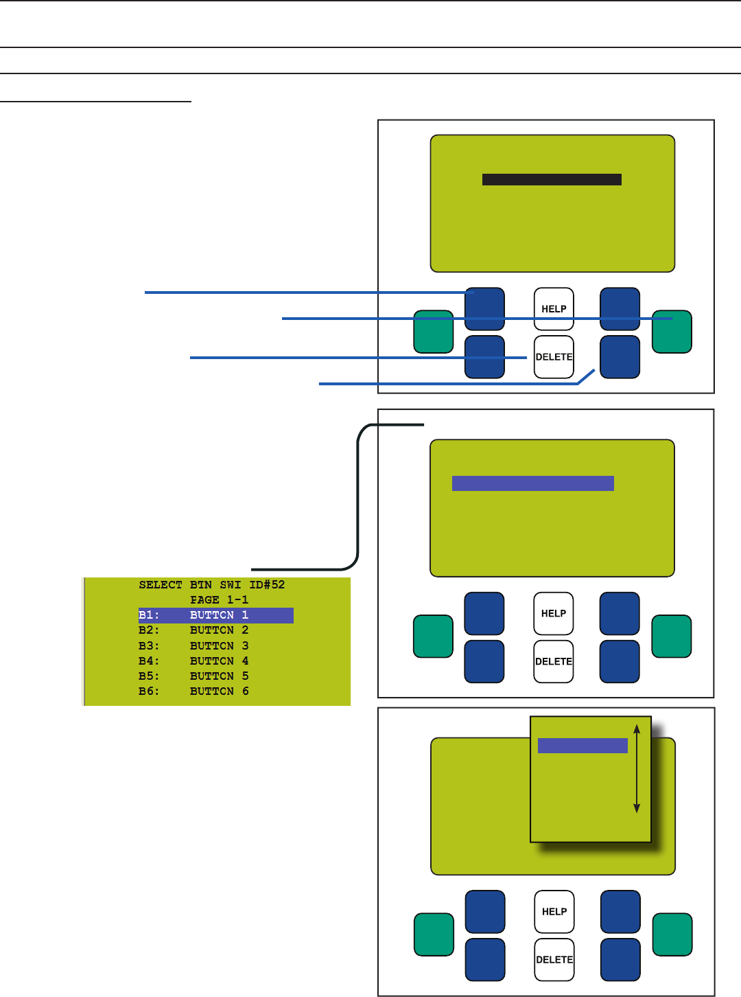
DTC Clock Navigation Basics
Tab to select a Button
Most devices in the digital lighting control system are
digital, meaning they are part of a peer-to-peer network
and can be programmed.
Programming is done from the DTC Clock/Programmer
located in the master Lighting Control Panel (LCP).
EXIT ENTER
SCROLL
UP
SCROLL
DOWN
TAB
UP
TAB
DOWN
EXIT ENTER
SCROLL
UP
SCROLL
DOWN
TAB
UP
TAB
DOWN
SWITCHES PAGE 1-2
#33: Reception
#52: Master Sw 1
#53: Master Sw 2
#59: Master Sw 3
#61: Hallway 100
#61: Hallway 200
#61: Hallway 220
Tab to select a switch. Press ENTER
EXIT ENTER
SCROLL
UP
SCROLL
DOWN
TAB
UP
TAB
DOWN
SW ID52-1 TOGGLE
EDIT: LCP-1
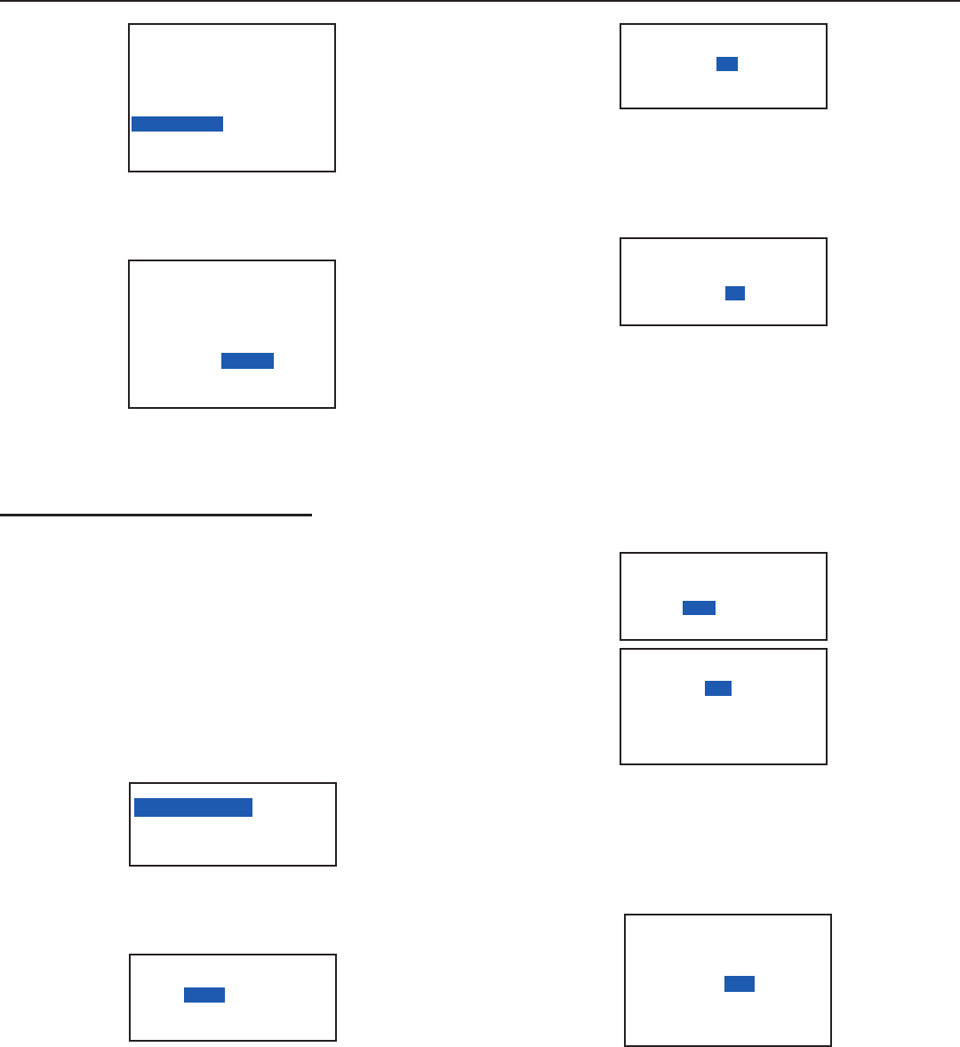
Tabbing
TAB UP or TAB DOWN to position the cursor ENTER
to select or drop into sub-menu
T
T
T
T
T
T
TO
GG
LE
MAINTAIN
TOGGLE
MIXED MODE
OFF MODE
ON MODE
GROUP 1
Scrolling
SCROLL UP or SCROLL DOWN to choose one item
from a “fi eld”*
TAB UP or TAB DOWN to exit the fi eld (by moving the
cursor to a different selection).
A “fi eld” is a display in which one of many items can *
be selected. In other words a value can be changed
by selecting a new one.
SCROLL through
choices in one fi eld
ENTER to select an
item or sub-menu
DELETE information or
programming about an
item. Use caution.
TAB to position
the cursor
USER MENU
__________________________
MANUAL OVERRIDE
REVIEW SCHEDULE
GROUP LOADS
PROGRAM SWITCH
SETUP MENU
9

Pg. 8 BLUE BOX Series Operations and Maintenance Manual
LCDBBO&M0M04Mar08
Manual control of relays
The manual override screen allows for manual control and
to visually check the (on/off) status of any relays(s) in any
panel(s).
The Auto/Hand indicator (see bottom figure) indicates if
the panel is in Auto or Hand mode. The letters “AU” indi-
cate the LCP is in Auto mode. The letters “MN” indicate
Hand mode.
To Start:
TAB once or twice to get started.1.
TAB to MANUAL OVERRIDE2.
ENTER to select.3.
USER MENU
MANUAL OVERRIDE
REVIEW SCHEDULE
GROUP LOADS
PROGRAM SWITCH
SETUP MENU
To Navigate to a LOAD (Relay):
If needed, TAB to LCP-11.
SCROLL to select the correct LCP (Lighting Control 2.
Panel)
TAB to LOAD-13.
SCROLL up or down to select the relay you wish to 4.
control.
MANUAL CONTROL AU
LCP-1 LOAD-1
1- 3■ 5■ 7■ 9- 11- 13- 15-
2- 4- 6- 8■ 10- 12- 14- 16-
Use the SCROLL
button to select the
correct LCP (systems
with multiple LCPs)
TAB to LOAD-1 and
SCROLL UP or DOWN
to select the relay
to manually control.
ENTER to change
the status of the relay
(load).
To Control a LOAD (Relay):
Press ENTER to toggle the status of the LOAD “off” or “on”.1.
MANUAL CONTROL AU
LCP-1 LOAD-1
1■ 3■ 5■ 7■ 9- 11- 13- 15-
2- 4- 6- 8■ 10- 12- 14- 16-
- indicates the Relay
(or LOAD) is off
■ indicates the Relay
(or LOAD) is on
Refer to Groups FAQ
for a complete
description of relay
status.
LOAD 9 is off. SCROLL
to “9” and ENTER to
turn it on.
LOAD 1 is on. Press
ENTER to turn it off.
MANUAL CONTROL AU
LCP-1 LOAD-1
1■ 3■ 5■ 7■ 9- 11- 13- 15-
2- 4- 6- 8■ 10- 12- 14- 16-
AU indicates this panel
is in AUTOMATIC
mode.
“MN” indicates this
panel is in HAND mode
Press EXIT several times to get back to the main 2.
screen.
Navigate to any Digital Switch or Photocell Card
Digital switches, photocell cards, and contact-closure inter-
faces are all located under the PROGRAM SWITCH sec-
tion.
To Start:
TAB to start.1.
TAB to PROGRAM SWITCH2.
ENTER to select.3.
USER MENU
MANUAL OVERRIDE
REVIEW SCHEDULE
GROUP LOADS
PROGRAM SWITCH
SETUP MENU
For Multiple Pages (more than 7 switches):
SCROLL to the correct Page1.
SWITCHES PAGE 1-2
#04: OFFICE 101
#05: OFFICE 102
#06: OFFICE 103
#07: OFFICE 104
#08: OFFICE 105
#09: OFFICE 106
#10: OFFICE 107
This indicates Page
1 of 2
If cursor starts here,
you have multiple
pages with switches on
each page. You may
need to navigate to the
correct page.
To Select Switch:
TAB to the correct Switch1.
ENTER to select2.
SWITCHES PAGE 2-2
#11: OFFICE 101
#12: OFFICE 102
#16: OFFICE 103
This is the digital
address of the switch
device.
Addresses which are
not used or which are
not for switches, will
not be displayed on
this list.
10

Pg. 9
LCDBBO&M0M04Mar08
To Select Button:
TAB to the correct Button1.
ENTER to select2.
SELECT BTN SW ID#11
PAGE 1-1
B1: BUTTON 1
B2: BUTTON 2
B3: BUTTON 3
B4: BUTTON 4
B5: BUTTON 5
B6: BUTTON 6
This indicates you have
selected Switch ID#11
“Select Button Menu”
This is Button 1 of
Switch ID 11
Adding or Deleting Loads (switches, photocell cards,
and groups)
Adding or deleting loads from a switch, a photocell card
or group is always done in the same way. Once you have
navigated to the correct button, trigger, or group (and
before you add or delete loads) it is important to determine
the Control Type (see the Control Types section of this
manual).
SCROLL to select Control Type.1.
TAB DOWN to LCP 12.
SWI ID13-1 MAINTAIN
EDIT: LCP-1 LOAD-1
Indicates Control Type
SCROLL to select
Control Type
(Refer to Control Types
Section)
For all Control Types (except Mixed Mode):
SCROLL to select LCP (1,2,3 etc)1.
TAB to LOAD 12.
SWI ID13-1 TOGGLE
EDIT: LCP-1 LOAD-1
LCP1: 1
SCROLL to choose
another LOAD (relay).
ENTER to add it to the
Load Summary
“Load Summary”
indicates what Loads
have been selected
Indicates Switch ID#13
Button 1
This indicates LCP1
Relay 1 has been
added to the Load
Summary
SCROLL to the LOAD you want to add or delete3.
ENTER to select LOAD - it will appear in the Load Sum-4.
mary
(ENTER again to delete LOAD)5.
Repeat to add or delete more LOADs6.
EXIT up to main menu.7.
For Mixed Mode:
SCROLL to Select LCP (1,2,3 etc)1.
TAB to LOAD 12.
SCROLL to the LOAD you want to add or delete3.
ENTER once to select LOAD ON.4.
Load Summary for
MIXED MODE shows
which LOADS will be
switched ON and which
will be switched OFF
SWI ID13-1 TOGGLE
EDIT: LCP-2 LOAD-3
ON LCP1: 1-3
OFF LCP2: 1-3
ENTER twice to select LOAD OFF5.
ENTER three times to delete LOAD6.
Repeat to add or delete more LOADs7.
EXIT up to main menu8.
To Delete a Load (from the Load Summary):
SCROLL to the LOAD1.
ENTER until the LOAD is deleted (no longer in the Load 2.
Summary).
SWI ID13-1 MIXED MODE
EDIT: LCP-1 LOAD-12
LCP1: 2-5,12
LCP2: 1,4
To delete “LCP1:12”
SCROLL to LCP 1
TAB to LOAD,
SCROLL to LOAD 12
ENTER until deleted
Time Schedules
Schedule Types
There are three schedule types:
EVERY DAY (7-day schedule)
The schedule will be on and off the same time every day of
the week. Holiday list may be excluded.
SCH 1 EXCEPT NONE
EVERY DAY
ON TIME: 09:00 AM
OFF TIME: 05:00 PM
9am to 5pm is default
time.
Schedule Type
(EVERY DAY is default)
11

Pg. 10 BLUE BOX Series Operations and Maintenance Manual
LCDBBO&M0M04Mar08
MON-FRI, SAT, SUN
The schedule will be on and off the same times from
Monday to Friday. Saturday and Sunday have separate
schedules. Holiday list may be excluded.
SCH 1 EXCEPT NONE
MONDAY - FRIDAY
ON TIME: 09:00 AM
OFF TIME: 05:00 PM
SAT ON TIME: 09:00 AM
OFF TIME: 05:00 PM
SUN ON TIME: 09:00 AM
OFF TIME: 05:00 PM
SCROLL to select
Mon-Fri,
Sat, Sun Schedule
BY DAY (unique for each day)
This is the most sophisticated schedule type.
Each day may have a separate on and off time which can
be edited to the nearest second.
This schedule can start and end on specific dates.
Up to two Holiday lists may be excluded or may have their
own schedules.
SCH 1
BY DAY H1 H2
MO TU WE TH FR SA SU
ON TIME: 09:00:00A
OFF TIME: 05:00:00P
FROM JAN 1 TO DEC 31
Monday Schedule
Summary
Start and stop date for
this schedule
SCROLL to select BY
DAY
Schedule
Trigger Events
ON TIME or OFF TIME are also called Time of Day (TOD)
events. To edit an ON or OFF TIME:
TAB to the Hours Minutes, and am/pm settings after ON 1.
TIME and SCROLL to adjust
ON TIME: 09:00 AM
OFF TIME: 05:00 PM
“DAWN (or DUSK) + or -” means minutes before or after
dawn or dusk.
TAB to “+ 0 mins” 1.
SCROLL up or down to select.2.
ON NONE
OFF NONE
ON DUSK -30MINS
OFF DAWN +30MINS
NONE is usually used for disabling a specific day or set of
days (i.e. Sunday).
SCROLL to select NONE.1.
SCH 1 EXCEPT NONE
MONDAY - FRIDAY
ON TIME: DUSK -30MINS
OFF TIME: 10:00 PM
SAT ON TIME: DUSK -30MINS
OFF TIME: 08:00 PM
SUN ON TIME: NONE
OFF TIME: NONE
ON DUSK -10MINS
OFF TIME: 10:00 PM
Trigger Events can
have mixed “on” and
“off” events including:
ON TIME, OFF TIME,
DUSK, DAWN, or even
NONE.
SCH 2 EXCEPT NONE
MONDAY - FRIDAY
ON TIME: 09:00 AM
OFF TIME: NONE
SAT ON TIME: NONE
OFF TIME: 05:00 PM
SUN ON TIME: NONE
OFF TIME: NONE
MIXED EVENT TRIGGERS event tirggers can be mixed
with ON TIME, OFF TIME, DUSK, DAWN, or even NONE
to create a variety of schedules.
PCEL ON/PCEL OFF are used when a photocell is con-
nected to the Photocell Input of the BLUE BOX panel. The
times shown after PCELL are the times the Photocell is
enabled (on) and disabled (off).
PCEL schedules require both ON and OFF times to be
programmed.
TAB to the Hours, Minutes, and am/pm settings after 1.
ON PCEL and SCROLL to adjust.
TAB to the Hour,s Minutes, and am/pm settings after 2.
OFF PCEL and SCROLL to adjust.
ON PCEL: 09:00AM
OFF PCEL: 05:00PM
PCEL needs both ON
and OFF times
To program the Photocell Trigger Levels, go to “Adjusting
Photocell Trigger Levels” section.
Editing Time Schedules
To Start:
TAB to start1.
TAB to REVIEW SCHEDULE and ENTER to select.2.
USER MENU
MANUAL OVERRIDE
REVIEW SCHEDULE
GROUP LOADS
PROGRAM SWITCH
SETUP MENU
12

Pg. 11
LCDBBO&M0M04Mar08
If needed SCROLL to the correct Page3.
TAB to a new or existing SCHEDULE and ENTER to select4.
SCHEDULES PAGE 1-6
NAME: SCHEDULE 1
SCH 1 UNUSED
SCH 2 UNUSED
SCH 3 UNUSED
SCH 4 ===> NO LOADS
SCH 5 UNUSED
SCH 6 UNUSED
Page 1 of 6. SCROLL
up to view more pages
This indicates schedule
1 is not programmed
This indicates schedule
4 is programmed but
with no loads added.
TAB to EVERY DAY and SCROLL to select the schedule 5.
type you want.
For EVERY DAY SCHEDULE:
TAB to ON TIME and OFF TIME and SCROLL to 1.
change the Trigger Event (see previous section) and
adjust as needed.
SCROLL to change
Schedule Type
To Add Holiday List
see Add a Holiday List
Section
SCH 1 EXCEPT NONE
EVERY DAY
ON TIME: 03:00PM
OFF PCEL: 10:00PM
MON-FRI, SAT, SUN SCHEDULE
TAB to ON TIME and OFF TIME for each day or group 1.
of days.
SCROLL to change the Trigger Event and adjust as 2.
needed.
SCH 1 EXCEPT NONE
MONDAY - FRIDAY
ON TIME: 09:00 AM
OFF TIME: 05:00 PM
SAT ON TIME: 11:00 AM
OFF TIME: 03:00 PM
SUN ON TIME: 11:00 AM
OFF TIME: 03:00 PM
TAB to each Trigger
Event and adjust per
Trigger Events Section
SAMPLE SCHEDULE #1:
SCH 1 EXCEPT NONE
MONDAY - FRIDAY
ON DUSK -30MINS
OFF TIME: 11:00 PM
SAT NONE
NONE
SUN NONE
NONE
The lights will be off
through the weekend
SAMPLE SCHEDULE #2:
SCH 1 EXCEPT NONE
MONDAY - FRIDAY
ON TIME: 09:00 AM
NONE
SAT NONE
OFF TIME: 02:00 PM
SUN NONE
NONE
This schedule will turn
on Monday morning
and will be reiterated at
9AM Tuesday to Friday,
and will stay on until
Saturday afternoon.
For BY DAY SCHEDULE:
Tab to any day and ENTER to edit that day.1.
This is the summary of
the Monday Schedule
TAB to Monday and
view the Trigger Event.
ENTER to edit.
SCH 1
BY DAY H1 H2
MO TU WE TH FR SA SU
ON TIME: 09:00:00A
OFF TIME: 05:00:00P
FROM JAN 1 TO DEC 31
TAB to ON TIME or OFF TIME and SCROLL to adjust 2.
Trigger Events.
ON TIME: 9:00:00 AM
OFF TIME: 5:00:00 PM
ADJUST THESE DAYS:
MON
EVERY DAY
Adjust per Trigger
Events Sections.
To Add These Settings to Other Days
TAB to Every Day (bottom screen)1.
SCROLL to the desired day or group of days and 2.
ENTER to select each. The days that are selected will
appear on the screen.
ON TIME: 11:30:00 AM
OFF TIME: 02:00:00 PM
ADJUST THESE DAYS:
MON, TUE, WED
THU
SCROLL and ENTER
to copy these settings
to other day(s)
This is a list of all the
days these settings are
going to be copied to.
EXIT and edit any schedules for other days.1.
To select start-date and end-date
TAB to JAN and SCROLL to adjust.1.
TAB to 1 and Scroll to adjust2.
Repeat as above to edit the end-date3.
EXIT when complete4.
Edit Schedule start
date and end date
here.
SCH 1
BY DAY H1 H2
MO TU WE TH FR SA SU
ON TIME: 09:00:00A
OFF TIME: 05:00:00P
FROM SEP 1 TO JUN 15
13

Pg. 12 BLUE BOX Series Operations and Maintenance Manual
LCDBBO&M0M04Mar08
ADVANCED PROGRAMMING
Programming Photocells Connected to a Photocell
Card
For applications that require more than one photocell, a
photocell card (such as the PCC3 CARD) can be used.
You can connect up to 3 photocells to the photocell card,
and individually enable and disable them based on time of
day, or when a user presses a switch.
Note: By default, photocells are active all the time once
programmed. In order to set up the disable/enable feature,
you will need a spare relay or an empty relay position on
any panel on the bus for each photocell you are disabling.
The programming for a photocell connected through a
photocell card is very similar to programming a switch. To
set up basic photocell programming (turn lights on below a
certain light level, turn them off above a certain light level),
use the following steps:
Basic Photocell Programming
Navigate to: USER MENU>PROGRAM SWITCH1.
Select the photocell card from the PROGRAM SWITCH 2.
menu and press ENTER to select it.
SSWITCHES PAGE 2-3
#31: SWITCH 31
#32: ANALOG/DIGI. 32
#33: LOBBY SW 1
#34: LOCCY SW 2
#35: SWITCH 35
#41: SWITCH 41
#45: CONCESSION SW 1
Press TAB DOWN to select a Trigger and press ENTER 3.
to select it.
SELECT BTN SWI ID#32
PAGE: 2-3
T1: TRIGGER 1
T2: TRIGGER 2
T3: TRIGGER 3
T4: TRIGGER 4
T5: TRIGGER 5
T6: TRIGGER 6
TAB to any unused
Trigger. Enter to select.
Press SCROLL UP or SCROLL DOWN to set the mode 4.
to MAINTAIN
SW ID#32-4 MAINTAIN
EDIT: LCP-1 LOAD-1
Add the desired loads (relays or zones).5.
SW ID#32-4 MAINTAIN
EDIT: LCP-1 LOAD-5
LCP1:1-3,5
Add the desired loads
(relays or zones).
TAB DOWN until you have highlighted the MAINTAIN 6.
setting in the top right corner. Now press ENTER to
access the trigger levels screen. SCROLL UP to select
which photocell you are going to use for this trigger.
Analog1 refers to the photocell plugged into the fi rst
input on the photocell card. Analog2 refers to the pho-
tocell plugged into the second input, etc. The number
immediately to the right of the input name is the current
light level reading for that input.
TAB to MAINTAIN and
ENTER to edit trigger
levels. To control more
than 8 relays, use a
Maintain Group.
SCROLL to select
Photosensor Card Input
ANALOG 1 (for input 1)
ANALOG 2 (for input 2)
ANALOG 3 (for input 3)
SENSOR ID#32-4
ANALOG1: 32
TIME DELAY: 01 MIN
ON WHEN LEVEL
FALLS BELOW: 20
OFF WHEN LEVEL
REISES ABOVE: 30
SW ID#32-4 MAINTAIN
EDIT: LCP-1 LOAD-5
LCP1:1-3,5
TAB DOWN to time delay and SCROLL UP and 7.
SCROLL DOWN to set the time value. We recommend
a delay of 10 minutes.
SENSOR ID#32-4
ANALOG1: 32
TIME DELAY: 10 MIN
ON WHEN LEVEL
FALLS BELOW: 20
OFF WHEN LEVEL
RAISES ABOVE: 30
The default setting for the “on” level (falls below) is 20. The
default setting for the “off” level (rises above) is 30. Try
these setting first. If they need to be adjusted do the fol-
lowing:
TAB DOWN to “on” trigger (falls below) and SCROLL •
to adjust.
SENSOR ID#32-4
ANALOG1: 32
TIME DELAY: 10 MIN
ON WHEN LEVEL
FALLS BELOW: 40
OFF WHEN LEVEL
RAISES ABOVE: 41
TAB to “off” trigger (rises above) and SCROLL to •
adjust.
SENSOR ID#32-4
ANALOG1: 32
TIME DELAY: 10 MIN
ON WHEN LEVEL
FALLS BELOW: 40
OFF WHEN LEVEL
RAISES ABOVE: 55
14

Pg. 13
LCDBBO&M0M04Mar08
!
A good way to determine the best light level settings is to
do the above steps at a time when the brightness about
matches when you want the lights to go on or off. For
example, set the Off (raises above) trigger in the morn-
ing when the sun is just coming up. Check the light level
reading on the clock when the area is bright enough for
the lights to shut off and use this reading as the “Off”
value. Similarly, set the On (falls below) trigger in the
evening when it is just getting dark enough so that the
lights should come on. Check the light level reading at
that time and use it as your “On” value.
The programming for this trigger on the photocell card is8.
now set. Press EXIT several times to return to the main
menu.
Enabling/Disabling Photocells:
There are applications where you may need to have a
photocell on the photocell card operate only during certain
times of the day, or you may want to be able to override
and ignore the photocell by pressing a switch.
To enable or disable a photocell, you set a special trigger
that “watches” a relay. When the relay is ON, the photo-
cell will be enabled, when it is OFF, the photocell will be
disabled. You can then assign that relay to a schedule
or a switch to control when the photocell is disabled and
enabled.
You will need one relay for each photocell that you want
to enable and disable separately (all 3 photocells enabled/
disabled at the same time could use one relay). You would
select an empty relay position or a spare relay since you
don’t want unrelated lights to turn on and off just because
you are making a photocell active or inactive.
Follow these steps to set up the enable/disable feature on
a photocell:
Setting Photocell Enable/Disable
Navigate to: USER MENU>PROGRAM SWITCH1.
Select the photocell card from the PROGRAM SWITCH2.
menu and press ENTER. The photocell card will display
as ANALOG/DIGI unless renamed.
SSWITCHES PAGE 2-3
#31: SWITCH 31
#32: ANALOG/DIGI. 32
#33: LOBBY SW 1
#34: LOCCY SW 2
#35: SWITCH 35
#41: SWITCH 41
#45: CONCESSION SW 1
The Pcc-3 will
dispay as “Analog/
Digi” followed by the
digital address unless
renamed (see the
Naming Menu)
SCROLL to page 2 and TAB DOWN to select Trigger3.
11, 12, or 13. These triggers are specially reserved
and can only be used for enabling/disabling photocells.
They are assigned as follows:
Trigger 11 --------- Enables / Disables Photocell Input 1
Trigger 12 --------- Enables / Disables Photocell Input 2
Trigger 13 --------- Enables / Disables Photocell Input 3
!
Do not use triggers 11-13 for normal photocell program-
ming! They will only function as enable/disable triggers.
For this example, we will set up enabling and disabling on
photocell input 1 -- so select Trigger 11 and press ENTER
to select it.
SELECT BTN SWI ID#32
PAGE: 2-3
T7: TRIGGER 7
T8: TRIGGER 8
T9: TRIGGER 9
T10: TRIGGER 10
T11: TRIGGER 11
T12: TRIGGER 12
Trigger 11 will enable
and disable Input 1 on
the Pcc-3
Press SCROLL UP or SCROLL DOWN to set the mode4.
to OFF MODE.
SW ID#32-11 OFF MODE
EDIT: LCP-1 LOAD-1
SCROLL to select
OFF MODE
Add any spare or empty relay position as the load (for5.
example LCP1: 16). Refer to Adding or Deleting Loads
section earlier in this manual for specifi c instructions on
how to add a relay to a switch or photocell.
SW ID#32-11 OFF MODE
EDIT: LCP-1 LOAD-16
LC1:16
Select an unused relay
TAB UP to OFF MODE and press ENTER to go to the6.
trigger levels screen. Use SCROLL UP to change the
input to DIGITAL 1.
SENSOR ID#32-11
DIGITAL 1
SW ID#32-11 OFF MODE
EDIT: LCP-1 LOAD-1
TAB To OFF MODE
and ENTER to to go to
the trigger screen.
SCROLL to select
DIGITAL 1
You have fi nished setting up the enable/disable feature.7.
Press EXIT several times to return to the main menu.
When the selected relay or relay position is on, the pho-
tocell connected to photocell input 1 will be enabled and
when off will be disabled.
15

Pg. 14 BLUE BOX Series Operations and Maintenance Manual
LCDBBO&M0M04Mar08
Now any digital device and/or time schedule can be pro-
grammed to enable and disable this photocell input, simply
by turning on or off the relay assigned to the enable trigger.
If you have additional photocells connected to inputs 2
and 3, you can set them up to be enabled/disabled using
the same steps above, but with Trigger 12 for input 2 and
Trigger 13 for input 3.
Special Note on Enabling Photocells During the Day:
When a photocell is disabled, its light level reading rap-
idly rises to maximum level (1020) and stays there until it
is enabled again. When enabled, the light level reading
descends from 1020 to the current light level.
This means that any trigger which is set to “Turn off when
light level rises above ______” will not be activated since
the light level is coming DOWN through the setpoints and
is not rising ABOVE any specific light level.
Consider the following scenario:
A photocell is set to turn off lights when the light level •
rises above “100.” The current light level is actually
200.
The photocell is disabled, causing it to read “1020.”•
When the photocell is re-enabled, you might expect it to
turn the lights off since it is supposed to turn lights off
when the light level rises above 100 and the current light
level is 200. However, because re-enabling the photocell
causes the light reading to come DOWN from 1020 to 200,
the photocell never “RISES ABOVE” 100 and thus will not
turn off the lights.
The solution is to set an additional trigger that will specifi-
cally turn off the lights if the photocell is enabled when it is
already bright outside.
This “Startup Trigger” controls the same loads as you
already assigned to the photocell earlier. Your earlier
programming will affect how the photocell operates when
it is active; this “Startup Trigger” is only used to specifically
turn lights off when the photocell is just enabled and it is
already bright outside.
YOU ONLY NEED TO DO THIS PROGRAMMING STEP
IF YOU HAVE A DISABLED PHOTOCELL THAT YOU
ENABLE AT SOME POINT DURING THE DAY WHEN
IT IS LIGHT OUTSIDE, AND IT IS NOT PROPERLY
SHUTTING LIGHTS OFF.
Setting the “Startup Trigger”
Navigate to: USER MENU>PROGRAM SWITCH1.
Select the photocell card from the PROGRAM SWITCH 2.
menu and press ENTER to select it.
SSWITCHES PAGE 2-3
#31: SWITCH 31
#32: ANALOG/DIGI. 32
#33: LOBBY SW 1
#34: LOCCY SW 2
#35: SWITCH 35
#41: SWITCH 41
#45: CONCESSION SW 1
The photocell card will
dispay as “Analog/
Digi” followed by the
digital address unless
renamed (see the
Naming Menu)
TAB DOWN to any unused trigger and press ENTER to 3.
select
SELECT BTN SWI ID#32
PAGE: 2-3
T1: TRIGGER 1
T2: TRIGGER 2
T3: TRIGGER 3
T4: TRIGGER 4
T5: TRIGGER 5
T6: TRIGGER 6
TAB to any unused
Trigger and ENTER to
select
SCROLL UP or SCROLL DOWN to set the mode to 4.
OFF MODE
SW ID#32-5 OFF MODE
EDIT: LCP-1 LOAD-1
SCROLL to
OFF MODE
Add the same loads that you previously set in the earlier 5.
trigger for this photocell. Then TAB DOWN to OFF
MODE and press ENTER to access the trigger levels
screen.
SW ID#32-5 OFF MODE
EDIT: LCP-1 LOAD-5
LCP1:1-3,5
Add the same loads as
the basic trigger.
TAB DOWN to time delay and SCROLL UP or SCROLL 6.
DOWN to set the time delay to 1 minute.
SENSOR ID#32-5
ANALOG01: 32
TIME DELAY:01 MIN
ON WHEN LIGHT LEVEL
FALLS BELOW: 20
Set the Time Delay to
1 Minute
TAB DOWN to RISES ABOVE and SCROLL DOWN to 7.
change it to FALLS BELOW.
16
Pg. 15
LCDBBO&M0M04Mar08
SCH 1 EXCEPT NONE
EVERY DAY
ON PCEL: 03:00PM
OFF PCEL: 05:00PM
TAB to hours and
minutes and SCROLL
to select “on” time
TAB to the time settings after OFF PCEL and SCROLL6.
to select an “off” time. This is the time that the photocell
will be “disabled” (not allowed to operate). When the
photocell is disabled, the group is also switched off.
SCH 1 EXCEPT NONE
EVERY DAY
ON PCEL: 03:00PM
OFF PCEL: 10:00PM
TAB to hours and
minutes and SCROLL
to select “off” time
For outdoor lighting, we recommend an “on” time of
about 3:00 PM and an “off” time that coincides with the
scheduled “off” time. For indoor (daylight harvesting)
we recommend a start time and end time which coin-
cides with the hours the space is occupied.
With the cursor on PCEL, ENTER to go to the trigger7.
settings. SCROLL to select “off” Time Delay (10 minutes
is usually recommended).
ON BOARD PHOTO CELL
ANALOG1: 32
TIME DELAY: 10 MIN
ON WHEN LEVEL
FALLS BELOW: 20
OFF WHEN LEVEL
REISES ABOVE: 30
SCH 1 EXCEPT NONE
EVERY DAY
ON PCEL: 03:00PM
OFF PCEL: 10:00PM
TAB to either PCEL and
ENTER to go to trigger
settings
In trigger settings you
can edit the “on” delay
and the “off” delay and
the on and off triggers
The default setting for the “on” level (falls below) is 20.8.
The default setting for the “off” level (rises above) is 30.
Try these setting fi rst. If they need to be adjusted do the
following:TAB DOWN to “off” trigger (raises above) and
SCROLL to adjust.
ON BOARD PHOTO CELL
READING: 32
DELAY TO OFF: 5MINS
OFF WHEN LEVEL
RAISES ABOVE: 40
DELAY TO ON: 5MINS
ON WHEN LEVEL
FALLS BELOW: 41
TAB DOWN to “off”
trigger (raises above)
and SCROLL to adjust.
TAB to ”on” trigger (falls below) and SCROLL to adjust.
SENSOR ID#32-5
ANALOG01: 32
TIME DELAY:01 MIN
ON WHEN LIGHT LEVEL
FALLS BELOW: 20
SCROLL to select
“Falls Below”
TAB DOWN to the trigger level and SCROLL UP to8.
1000.
SENSOR ID#32-5
READING: 32
TIME DELAY:01 MIN
ON WHEN LIGHT LEVEL
FALLS BELOW: 1000
SCROLL to select 1000
You’re done setting the “Startup Trigger.” Press EXIT9.
several times to return to the main menu.
Programming a BLUE BOX Photocell
When an outdoor photocell is plugged directly into the
BLUE BOX master panel, the photocell is programmed as
part of a time schedule (available for schedules 1-8 only).
Navigate to: USER MENU>REVIEW SCHEDULE1.
Use the SCROLL and TAB keys to navigate to the de-2.
sired schedule. ENTER to select.
SCROLL to select schedule type (EVERYDAY, BY DAY,3.
M-F S S).
SCH 1 EXCEPT NONE
EVERY DAY
ON TIME:09:00AM
OFF TIME:05:00PM
SCROLL to select
schedule type
TAB to “on time” for each day or group of days and4.
SCROLL to select PCEL.
SCH 1 EXCEPT NONE
EVERY DAY
ON PCEL:09:00AM
OFF PCEL:05:00PM
SCROLL to select
PCEL
TAB to the time settings after ON PCEL and SCROLL5.
to select an “on” time. This is the time that the photocell
will be “enabled.” When enabled, the group is switched
on only if the light levels are below the ON trigger,
otherwise they will remain OFF until the light levels drop
below the ON trigger.
17

Pg. 16 BLUE BOX Series Operations and Maintenance Manual
LCDBBO&M0M04Mar08
ON BOARD PHOTO CELL
READING: 32
DELAY TO OFF: 5MINS
OFF WHEN LEVEL
RAISES ABOVE: 40
DELAY TO ON: 5MINS
ON WHEN LEVEL
FALLS BELOW: 41
!
A good way to determine the best light level settings is to
do the above steps at a time when the brightness about
matches when you want the lights to go on or off. For
example, set the Off (raises above) trigger in the morn-
ing when the sun is just coming up. Check the light level
reading on the clock when the area is bright enough for
the lights to shut off and use this reading as the “Off”
value. Similarly, set the On (falls below) trigger in the
evening when it is just getting dark enough so that the
lights should come on. Check the light level reading at
that time and use it as your “On” value.
EXIT and SAVE.9.
To add loads(relays) to this schedule:10.
If this is a new schedule, TAB DOWN once to NO•
LOADS and ENTER to add Loads (relays). You will be
creating a GROUP, so refer to the section on Adding
Groups.If this is an existing schedule, TAB DOWN
once to the existing GROUP and ENTER to add or
delete Loads (relays) to this Group. Refer to the sec-
tion on Adding Groups.
!
The group controlled by the photocell is, in almost all
cases, going to be set as MAINTAIN. MAINTAIN in this
case will allow the photocell to turn the lights on and off,
and with the built in on and off times is also time sensi-
tive.
GROUP 1 MAINTAIN
EDIT: LCP-1 LOAD-5
LCP1:1,2,5
Use a MAINTAIN group
for most photosensor
settings.
Control Types
“Control Types” describes how loads are controlled. When
controlling more than 8 relays or for any time schedule,
“Groups” must be used and the Toggle feature is not avail-
able.
TOGGLE A momentary contact will toggle up
to 8 loads on or off.
ON MODE A momentary contact will issue an
“on” command to as many as 8
loads.
OFF MODE A momentary contact will issue an
“off” command to as many as 8
loads.
MIXED MODE
Also known as an “interlock.” A
momentary contact will switch one
set of loads “on” and another set of
loads “off.”
MAINTAIN
Loads are ON for the duration of a
closure and OFF when the closure
is opened. Similar to the way a
wall switch makes and then breaks
a circuit to turn lights on or off.
Photosensor Card Triggers are usu-
ally programmed as maintain, as
is any maintained contact closure
device such as a wall switch or a
relay closure from (for instance) a
security system.
GROUPs
(1-32)
To control more than 8 loads, or
when programming a time sched-
ule, always use GROUPs.
Last Input Override
Your digital lighting controls use a logic structure called
“last input override” and as such other inputs can affect the
loads too. For example: If a load is toggled on, from one
location, and then switched off by a time schedule; If acti-
vated, the toggle switch will turn the loads back on - last
input override.
Group Types
A group describes two things: which relays are controlled
together, and how they are controlled. Groups MUST BE
USED when controlling more than 8 relays and with all
time schedules.
Up to 32 groups are available and each group can range in
size from a single relay to all relay(s) in all panel(s).
There are two types of Groups:
Maintain Style Groups
18

Pg. 17
LCDBBO&M0M04Mar08
Just like the maintain control, starting a maintain contact
(or a time schedule) will turn a maintain style group on,
and when the contact is open or the schedule is off, the
group is turned off.
When a Maintain style group is first switched on, the relays
within that group are switched on too, with one exception.
(See NO AUTOMATIC ON option under Programming
Groups)
While the Group is “on” the relays within that group will
respond normally when switched on and off by a digital
wall switch.
When the group is switched off, so are the relays, with one
exception (see MAINTAIN + BLINK below).
When “Maintain+Timer” or “Maintain+Off Sweep” Groups
are off the relays are in “timer mode”: which means if the
relays are turned on when the Group is off, they will remain
on for a (programmable) timed period.
Maintained Groups are used in the following circumstanc-
es:
Time schedules usually use a Maintain style group.1.
When a photocell is connected to a photocell card (not 2.
directly to the BLUE BOX panel) and turns more than 8
relays both on and off,
When relays need to be in “timer mode” after hours.3.
(BASIC)
MAINTAIN
GROUP
Used by time schedules or for any
maintained device (eg. photosensor
card triggers) controlling more than
8 loads. When the GROUP is ON
the loads are ON, and when the
GROUP is OFF, the loads are OFF.
MAINTAIN +
TIMER
GROUP
Usually used only with Time
Schedules. When the GROUP is
ON, the loads are ON. When the
GROUP is OFF and relays in that
GROUP are in Timer Mode, timer
duration is programmable.
MAINTAIN +
BLINK
GROUP
All the features of the MAINTAIN +
TIMER and adds a “blink” or “flick”
warning prior to shutting loads off.
Momentary Style Groups
Any momentary pulse or rising edge will trigger a momen-
tary group. Momentary groups are not turned on or off.
Momentary style Groups are used in the following circum-
stances to turn relays on or off:
When a digital switch, a contact closure or a photocell 1.
trigger switches more than 8 relays either “on” or “off”
When a time schedule only switches relays either “on” 2.
or “off,” but not both
MOMENTARY
ON
“On Mode” more than 8 loads
MOMENTARY
OFF
“Off Mode” more than 8 loads
MOMENTARY
MIXED
“Mixed Mode” more than 8 loads
For more information on groups, please refer to the Groups
FAQ.
Programming Groups
To Access a Group
Within the DTC, there are two paths you can use to access
a group for programming purposes:
From USER MENU:
Navigate to: USER MENU>GROUP LOADS and EN-1.
TER to select
USER MENU
MANUAL OVERRIDE
REVIEW SCHEDULE
GROUP LOADS
PROGRAM SWITCH
SETUP MENU
SCROLL to the correct page. (1 through 6) and TAB 2.
to the desired GROUP. ENTER to edit or create the
GROUP.
GROUPS PAGE 1-6
GROUP 1 UNUSED OFF
GROUP 2 UNUSED OFF
GROUP 3 USED MOM
GROUP 4 USED ON
GROUP 5 USED ON
GROUP 6 UNUSED OFF
This group does not
have any loads
Mometary Group
This Group has loads
and is on
TAB to a group and
SCROLL up or down to
change the status.
Enter to edit the group
From the SCHEDULE MENU:
EXIT schedule when complete with programming and 1.
TAB DOWN once to NO LOADS, or GROUP (X). EN-
TER to edit or create the GROUP
SCHEDULES PAGE 1-6
NAME: SCHEDULE 1
SCH 1 ==> NO LOADS
SCH 2 UNUSED
SCH 3 UNUSED
SCH 4 ==> GROUP 4
SCH 5 UNUSED
SCH 6 ==> DISABLED
Schedule 4 is
programmed and
controls GROUP 4
Schedule 6 is
programmed, but is
disabled
Schedule 1 is
programmed and
has no loads
Schedule 3 is not
programmed
To Edit a Group
19

Pg. 18 BLUE BOX Series Operations and Maintenance Manual
LCDBBO&M0M04Mar08
SCROLL to select the desired Group Type1.
GROUP 1 MAINTAIN
EDIT: LCP-1 LOAD-1
Refer to Page 12 for
information on Group
Types
Add or delete loads2.
EXIT when complete.3.
Additional Programming for Maintain + Timer Groups
With the Cursor positioned on MNTN + TIMER, ENTER1.
to edit the duration of the timer mode for the relays in
that GROUP.
This will determine how long relays are allowed to be
“on” when the GROUP is OFF.
GROUP 1 MNTN + TIMER
EDIT: LCP-1 LOAD-1
SCROLL to select AUTOMATIC ON or NO AUTOMATIC2.
ON.
AUTOMATIC ON is the default.
GROUP X PARAMETERS
AUTOMATIC ON
TIMER OUT: 2:00:00 HR
See Relay Timer
section for more
information on
individual relay timers
SCROLL to select:
AUTOMATIC ON
or
NO AUTOMATIC ON
AUTOMATIC ON means that the schedule will turn the
lights on, and the relays are taken out of Timer Mode.
AUTOMATIC ON is preferred for large area controls
such as a retail sales floor, or egress areas.
NO AUTOMATIC ON means that the schedule
will NOT turn the relays on (instead the relays are
switched on with a digital wall switch usually by the
first person to enter the space) and the relays are
taken out of Timer Mode. NO AUTOMATIC ON is pre-
ferred when lights can be switched on and off locally
with a digital wall switch.
TAB to TIMER OUT and SCROLL to adjust hours,3.
minutes and seconds. Four hours is the maximum timer
allowed.
This is the timer value
for each relay when the
group is off.
GROUP X PARAMETERS
AUTOMATIC ON
TIMER OUT: 2:00:00 HR
Additional Programming for Maintain + Blink Groups
With the Cursor positioned on MNTN + BLINK, ENTER1.
to adjust the timer mode, the time delay between the
fl ick warning and the lights being shut off, and to set
AUTOMATIC ON.
GROUP 1 MNTN+OFFSWEEP
EDIT: LCP-1 LOAD-1
SCROLL to select AUTOMATIC ON or NO AUTOMATIC2.
ON. (see above for more information)
TAB to TIMER OUT. and SCROLL to adjust hours, min-3.
utes and seconds.
TAB to OFF SWEEP and SCROLL to adjust the time4.
delay.
This is the time delay
between the fl ick
warning and the lighting
shut-off
GROUP X PARAMETERS
AUTOMATIC ON
TIMER OUT: 2:00:00 HR
OFF SWEEP: 05:00 MINS
For more information on Groups, please refer to the
Groups FAQ.
Programming BLUE BOX Inputs
A contact closure device when plugged into the inputs of
the BLUE BOX can be programmed to control any relay(s)
in any panel(s). 14 contact closure inputs are available on
each BLUE BOX panel . This section details how to pro-
gram these inputs. For hook-up details, refer to the BLUE
BOX panel Installation Guide.
Navigate to: USER MENU>PROGRAM SWITCH1.
Use the SCROLL and TAB keys to navigate to the BLUE2.
BOX panel Inputs. ENTER to select.
SWITCHES PAGE 1-2
#3: 14 BTN SW 3
#4: SWITCH 05
#5: SWITCH 06
#7: SWITCH 07
#8: SWITCH 08
#11: SWITCH 11
#12: SWITCH 12
The BLUE BOX Inputs
will display as a 14
Button Switch. Make
sure you have the
correct device!
SCROLL and TAB to the input (BUTTON) you wish to3.
edit and ENTER to select
SCROLL to select Control Type.4.
20

Pg. 19
LCDBBO&M0M04Mar08
SWI ID63-1 MAINTAIN
EDIT: LCP-1 LOAD-1
TAB DOWN to LCP 15.
For all Control Types (except Mixed Mode):
SCROLL to Select LCP (1,2,3 etc)1.
TAB to LOAD 12.
SCROLL to the LOAD you want to Add or Delete, and 3.
hit ENTER to select
SWI ID63-1 TOGGLE
EDIT: LCP-1 LOAD-1
LCP1: 1
ENTER to select
Load Summary
(ENTER again to delete LOAD). 4.
Repeat to add or delete more LOADs5.
ENTER to select
Load Summary
SWI ID63-1 TOGGLE
EDIT: LCP-1 LOAD-12
LCP1: 2-5,12
LCP2: 1,4
EXIT up to Main Menu.6.
For Mixed Mode:
SCROLL to Select LCP 1.
TAB to LOAD 1 and SCROLL to the LOAD you want to 2.
Add or Delete
ENTER once to select LOAD ON.3.
ENTER twice to select LOAD OFF4.
ENTER three times to delete LOAD from the Load Sum-5.
mary
ENTER once for ON
ENTER twice for OFF
Load Summary shows
ON and OFF loads
SWI ID63-1 TOGGLE
EDIT: LCP-2 LOAD-3
ON LCP1: 1-3
OFF LCP2: 1-3
Repeat to add or delete more LOADs6.
EXIT up to Main Menu7.
To Delete a Load
(from the Load Summary):
SCROLL to the LOAD. Make sure you have selected 1.
the correct LCP!
ENTER until the LOAD is deleted (no longer in the Load 2.
Summary). Add loads per the Adding/Deleting Loads
Section.
ENTER once to add
ENTER twice to delete
Load Summary
SWI ID63-1 TOGGLE
EDIT: LCP-1 LOAD-12
LCP1: 2-5,12
SWI ID63-1 MIXED MODE
EDIT: LCP-2 LOAD-3
ON LCP1: 1-3
OFF LCP2: 1-3
ENTER once for ON
ENTER twice for OFF
ENTER thrice to delete
Load Summary shows
ON and OFF loads
(MIXED MODE ONLY)
EXIT and SAVE.3.
To Add a Holiday List to a Schedule
The system offers up to 2 separate editable Holiday Lists.
This portion of the menu allows you to select from pre-
existing Holiday Lists. See Edit Create Holiday List for
instructions on how create or edit a new Holiday List.
EVERY DAY & MON-FRI, SAT, SUN SCHEDULE
These two schedules only allow the Holiday Lists to be
exempted from the schedule.
Follow this path: USER MENU › REVIEW SCHEDULE1.
SCROLL to the correct page and then TAB to the 2.
SCHEDULE you wish to add a Holiday List to
TAB to EXCEPT NONE3.
SCROLL to
select which
Holiday List is
exempt.
SCH 1 EXCEPT NONE
EVERY DAY
ON TIME: 09:00 AM
OFF TIME: 05:00 PM
SCROLL to the desired Holiday Exception setting4.
TAB to the EVERY DAY to continue editing5.
BY DAY SCHEDULE
This schedule allows one or both of the Holiday Lists to
be exempted, or even a new schedule created just for the
days included in the Holiday List.
21

Pg. 20 BLUE BOX Series Operations and Maintenance Manual
LCDBBO&M0M04Mar08
Follow this path: USER MENU › REVIEW SCHEDULE1.
SCROLL to the correct page and then TAB to the 2.
SCHEDULE you wish to add a Holiday List
TAB to either H1 or H2. - the two Holiday Lists. Both 3.
can be selected, but only individually.
Press ENTER to go to the Holiday options menu. 4.
ENTER to go
to the Holiday
Options Menu
SCH 1
BY DAY H1 H2
MO TU WE TH FR SA SU
ON TIME: 09:00:00A
OFF TIME: 05:00:00P
FROM JAN 1 TO DEC 31
SCROLL to select the desired Holiday option. There are 5.
three choices:
Do Not Omit (default) - the days on this holiday list will •
be included in this schedule.
•
Omit - the days on this holiday list will not be included
in this schedule.
ON-OFF schedule - the days on this holiday list will •
have unique schedules.
To create a special sub-schedule for this Holiday List, do 6.
the following:
TAB to ON TIME •
Scroll to select Schedule Type (see Schedule Types •
Section).
Select and edit Event Triggers (see Editing Event Trig-7.
gers Section).
ON-OFF SCHEDULE
ON TIME: 9:00:00 AM
OFF TIME: 5:00:00 PM
EXIT to move back to main schedule page.8.
To Edit a Holiday List
The Holiday lists contain no Holidays until they are edited.
Two separate holiday lists may be created and edited.
Follow this path: USER MENU › SETUP MENU › SYS-1.
TEM SETUP MENU › EDIT HOLIDAYS
SYSTEM SETUP MENU
SET TIME AND DATE
EDIT HOLIDAYS
SYSTEM OPTIONS
WHAT AND WHEN?
ADDRESSING-BUS SCAN
SCROLL to select page2.
TAB to the Holiday3.
HOLIDAY LIST 1 - PAGE 2
DATE: DEC 25
LABOUR: NO
COLUMBUS: NO
VETERANS: NO
THANKS GIV.: NO
CHRISTMAS: YES
BOXING: NO
SCROLL to YES to select4.
To add new Holidays to a Holiday List, SCROLL to page 5.
3 and TAB to the fi rst unused date.
HOLIDAY LIST 1 - PAGE 3
DATE: MAR 13
MAY 5 2007: YES
JAN 1 2007: NO
JAN 1 2007: NO
JAN 1 2007: NO
JAN 1 2007: NO
JAN 1 2007: NO
TAB to month, day and year and SCROLL to adjust. 6.
EXIT when complete.7.
Group FAQs
Q: What is the difference between “momentary” type
groups and “maintain” type groups?
A: - A maintain group can be turned ON and OFF. Once it
is turned ON, it stays on until turned OFF by a sched-
ule or other switch. When it is turned OFF, it stays
OFF until turned ON by a schedule or switch.
- A momentary group does not turn on and off. It only
sends a single signal to the relays in the group at the
moment it is activated. A MOMENTARY ON group can
only turn its relays ON, never OFF. A MOMENTARY
OFF group will always turns its relays OFF.
Q: Which type of group is most commonly used for sched-
ules and why?
A: Usually schedules operate “maintain” type groups. This
is because schedules are used to turn lights on and
have them stay on for a period of time, and then turn
them off. Only maintain groups can be turned on and
off.
22

Pg. 21
LCDBBO&M0M04Mar08
Q: When would you use a “momentary” type group with a
schedule?
A: In those rare instances when a schedule needs to
just turn lights on (without a corresponding off com-
mand) or off (without a corresponding on command).
For example, if you wanted the lights turned off by a
schedule at 8pm every day, but didn’t want any on
time, you would create a schedule that activates a
Momentary OFF group.
Q: What does a momentary mix group do?
A: It turns some relays ON and some relays OFF.
Q: What does a maintain group do?
A: When the maintain group is turned ON, it turns its relays
ON. When it is turned OFF, it turns its relays OFF.
Q: What does a MAINTAIN + TIMER group do?
A: When it is turned ON, it turns its relays ON. When it is
turned OFF, it turns off its relays AND enables a timer
on each relay. If any of the relays in timer mode are
flipped on with a switch, etc., they will automatically
turn back off again after a certain amount of time.
Q: How do you tell if a relay has a timer and what timer
value is?
A: If you check the relay properties screen for that relay,
it will say TIMER: followed by a number, e.g. TIMER
00:20:00 h/m/s
Q: How do you tell if a relay timer is active?
A: If the relay is on, the manual override screen will show
the normal ON square symbol with an additional little
“leg” on the bottom left corner, like this:
Relay on with no timer:
Relay on in timer mode:
Q: What does a MAINTAIN + BLINK group do?
A: It is identical to a MAINTAIN + TIMER group, with the
only addition being that when you turn a MAINTAIN +
BLINK group OFF, the lights will blink or flick, and then
wait for a specified amount of time before the relay
turns off. This time period is called the “Blink time out.”
This time period is set in the MAINTAIN + BLINK group
under “blink warning”.
Q: How do you take a relay out of timer mode?
A: Find out what MAINTAIN + TIMER or MAINTAIN +
BLINK group that relay is in, and turn that group ON.
Q: How can you tell if a relay has a “Blink Timer”?
A: If you check the relay properties screen for that relay, it
will say BLINK WARNING: followed by a number, e.g.
BLINK WARNING 20:00 m/s
Q: How can you tell if a relay is on a blink warning time-
out?
A: The manual override screen will show the relay as
being on with TWO little legs on the bottom corners, as
shown here:
Relay on with no offsweep or timer:
Relay in final Blink Warning Timer:
Q: What is the purpose of the “Blink time OUT.”
A: It gives the occupants of the area a warning that the
lights are about to turn off. They can extend the time
that they have light by pushing any button with a rap-
idly blinking LED. This is the indication that the lights
are in Blink Time OUT
Q: Where are relay timer properties physically stored?
A: Within the relays properties.
Q: Where are the two locations on the DTC that a relay
timer can be viewed or programmed?
A: USER MENU>GROUP LOADS>TAB to
GROUP>ENTER to select>TAB to MAINTAIN+TIMER
or MAINTAIN+BLINK>ENTER to select>
A: USER MENU>SETUP>SYSTEM
SETUP>RESTRICTED>RELAY PROPERTIES>select
BOARD>
Q: You create a new MAINTAIN group or add new relays
to an existing MAINTAIN Group and EXIT. Upon re-
entering the group, you notice it has changed itself into
MAINTAIN+TIMER. Why?
A: One or more of the relays in the group are also in
another MAINTAIN+TIMER or MAINTAIN+BLINK group
which has assigned it or them a timer value. Since the
timer value is written into the relay properties, it is car-
ried over into the new MAINTAIN group.
Q: What does MAINTAIN mean in reference to a wall
switch?
A: It means that the switch concerned is a contact closure
switch like an ordinary wall switch. When one flips the
switch UP the contacts close and stay closed and the
lights come ON. (They are MAINTAINED that way.)
When one flips the switch down the contacts open
and the lights go off. Note that both making the circuit
and breaking the circuit (from the switch to the contact
input) causes the relay(s) to react .
Q: What does MOMENTARY mean in reference to a
switch?
A: It means that a momentary pulse or a maintained clo-
sure from any switch will cause the relays to react but
unlike a MAINTAINED input opening the contact will
not cause the relay(s) to react.
23

Pg. 22 BLUE BOX Series Operations and Maintenance Manual
LCDBBO&M0M04Mar08
Q. How do you find out which group(s) a relay is in?
A. Go to the following screen in the clock: SETUP >
SYSTEM SETUP > WHAT AND WHEN? > WHAT
CONTROLS RELAYS. Select the relay and press
ENTER. Any groups that the relay is in will be dis-
played.
Q. How do you find out what is turning a group off or on?
A. Go to the following screen in the clock: SETUP >
SYSTEM SETUP > WHAT AND WHEN? > WHAT
CONTROLS GROUPS. Select the group and press
ENTER. Any schedules, photocells or switches that
control that group will be displayed.
Q: How do you manually turn on a group using the clock
interface?
A: Go to the “group loads” screen, highlight the group:
For a MOMENTARY ON group SCROLL UP to turn the 1.
relays in that group on,
For a MOMENTARY OFF group SCROLL UP to turn the 2.
relays in that group off,
For a MOMENTARY MIXED group SCROLL UP to 3.
control the relays per the ON and OFF schedule within
that group,
For any MAINTAIN group, SCROLL UP to turn the 4.
group on and SCROLL DOWN to turn the group off.
Q: What do you do to synch up the relays in a group, when
some of them are on and some are off?
A: Go to the “group loads” screen and turn on the group
again using the SCROLL UP button.
Q: How do you get rid of a group you don’t want to use
anymore?
A: Go to the “GROUP LOADS” screen, highlight the group
and press the DELETE button.
Q: What should you suspect is happening when you delete
a group but the relays still have a timer?
A: Those relays are in another MAINTAIN+TIMER or
MAINTAIN+BLINK group which is forcing a timer onto
them.
Q: What should you be careful never to do with MAINTAIN
+ TIMER or MAINTAIN + BLINK groups?
A: Never have the same relay in more than one
MAINTAIN + TIMER or MAINTAIN + BLINK group.
Q: What does the “NO AUTOMATIC ON” setting in a
MAINTAIN+TIMER or MAINTAIN+BLINK do?
A: It makes it so that when you turn ON the group, the
relays don’t come on – only the group status changes
to ON and the relay timers are disabled.
Q: Why would someone want to use “NO AUTOMATIC
ON”?
A: So they can take disable relay-timers without actually
turning the relays on. For example, if the customer
wants to turn lights on with a switch early in the
morning, and not have them automatically shut off
after an hour (timer mode), they would need to turn
the MAINTAIN + TIMER group on with a schedule.
However, if they don’t want the actual lights to turn on
until they use a switch, they would set the group to
“No Auto On”. This would take the relays out of Timer
mode, but not flip them on with the schedule until they
actually hit the switch.
Q: When must a switch button be programmed to operate
a group instead of just operating the relays directly?
A: When you want the switch to operate more than 8
relays, the system will require you to make them into a
group.
Q: How do you toggle a group on and off using a single
switch button?
A: You can’t. Groups cannot be toggled. If you want
to turn more than 8 relays on and off with a switch,
you need to use two buttons and two groups: one
MOMENTARY On and one MOMENTARY OFF.
Q: What kind of group would you normally NOT assign to
a momentary switch?
A: You normally do NOT assign any of the main-
tain-type groups (MAINTAIN, MAINTAIN+TIMER,
MAINTAIN+BLINK) to a switch. The reason for this
is that switch buttons turn maintain groups ON when
the button is held down and OFF when the button is
released. Having to hold the button down to keep
lights on is not generally useful for a customer!
Q: If you are having a photocell control more than 8
relays, what type of group would you assign to the
photocell?
A: You would normally use a maintain-type group.
Remember that only maintain-type groups can be
turned on AND off. If you want the photocell to turn
lights ON when it is dark and OFF when it is bright, the
easiest way is to use a maintain group.
Q: When would you use a momentary-type group with a
photocell?
A: When you only want the photocell to turn the relays
OFF, or only want it to turn relays ON. For example, if
you have a customer who wants a lot of relays to turn
on when it’s dark, but only to get shut off by a sched-
ule or a switch (not by the photocell), you could assign
a MOMENTARY ON group to the photocell.
24

Pg. 23
LCDBBO&M0M04Mar08
TIME SCHEDULE AND GROUP PRO-
GRAMMING EXAMPLES
Exercise #1- Contact Closure Device Controlling 4
Relays
The client wants to have a Security System turn on
LCP1: 1-4 for the duration of an “Alarm Mode” event. The
Security System will issue a maintained closure for the
duration of the event through Input 1 of a contact-closure
interface. What do you do?
Solution:
Program Input 1 of the contact-closure interface to control
LCP 1: 1-4 with a MAINTAIN type of control group.
Address 5 is a 14 Btn
Input. Its either the
Blue Box contact inputs
or a DigiLink
Select Maintain (refer
to Control Types)
Add LCP 1: 1-4
SWITCHES PAGE 1-2
#5: 14 BTN SW 5
#6: SWITCH 06
#7: SWITCH 07
#8: SWITCH 08
SWI ID05-1 MAINTAIN
EDIT: LCP-1 LOAD- 4
LCP1:1-4
Exercise #2 - Contact Closure Device Controlling 10
Relays
The same requirements as Exercise #1 but the customer
wants the security system to control 10 relays (LCP1 1-10)
instead of four.
Create a MAINTAIN group to control LCP1: 1-101.
Select Maintain (refer
to Group Types)
Add LCP 1: 1-4
GROUPS PAGE 1-6
NAME: GROUP 1
GROUP 1 UNUSED OFF
GROUP 2 UNUSED OFF
GROUP 3 USED MOM
GROUP 4 USED ON
GROUP 5 USED OFF
GROUP 6 UNUSED OFF
GROUP 2 MAINTAIN
EDIT: LCP-1 LOAD-10
LCP1:1-10
Program an Input of the contact-closure interface to2.
control the group you just created.
Address 5 is a 14 Btn
Input. Its either the Blue
Box inputs or a DigiLink
SWITCHES PAGE 1-2
#5: 14 BTN SW 5
#6: SWITCH 06
#7: SWITCH 07
#8: SWITCH 08
SWI ID05-1 GROUP 2
EDIT: LCP-1 LOAD-1
Exercise #3 - Time schedules with override switches
The client wants a time schedule for indoor lights start-
ing at 7:00 am and off at 5:30 pm. After hours the digital
switches can turn the lights on but only for two hours. Also,
the clients want to warn occupants five minutes prior shut-
off. What do you do?
Solution:
Set up a schedule: ON: 7:00 AM & OFF: 5:30 PM.1.
SCH 4 EXCEPT NONE
EVERY DAY
ON TIME: 07:00 AM
OFF TIME: 05:30 PM
The schedule will control a MAINTAIN+GROUP group2.
with a 2 hour timer, and 5 minute fl ick warning. Select
the relays for this group as needed.
To prevent the lights from all coming on at 7:00 am,
select NO AUTOMATIC ON, and then the local digital
switches will turn the lights on and the schedule will
turn the lights off. This is optimal for energy savings
when local digital switches are used.
TAB to NO LOADS and Enter
to edit. This will create a
new Group (refer to Groups
Section)
SCHEDULES PAGE 1-6
NAME: SCHEDULE 1
SCH 1 ==> GROUP 1
SCH 2 UNUSED
SCH 3 UNUSED
SCH 4 ==> NO LOADS
SCH 5 UNUSED
SCH 6 ==> DISABLED
GROUP 4 MNTN+BLINK
EDIT: LCP-1 LOAD-1
LCP1:1-12
GROUP 4 PARAMETERS
AUTOMATIC ON
TIMER OUT: 1:00:00 HR
OFF SWEEP: 05:00 MINS
Select
AUTOMATIC ON
One Hr. Timer
Five Min. Flick Wanring
Program each switch button with a Toggle or On Mode3.
control type (refer to Control Types) and set it to control
the relays as needed.
25

Pg. 24 BLUE BOX Series Operations and Maintenance Manual
LCDBBO&M0M04Mar08
Address 6 has been
named the OPEN
OFFICE SW1. (Refer
to Naming Switches).
SWITCHES PAGE 1-2
#5: 14 BTN SW 5
#6: OPEN OFFICE SW1
#7: OPEN OFFCE SW2
#8: RECEPTION
SELECT BTN SW ID#06
PAGE 1-1
B1: BUTTON 1
B2: BUTTON 2
B3: BUTTON 3
B4: BUTTON 4
B5: BUTTON 5
B6: BUTTON 6
Select TOGGLE or ON
MODE (refer to Control
Types)
Add any relays in the
group
SWI ID06-2 ON MODE
EDIT: LCP-1 LOAD-3
LCP1:1,3
Exercise #4
A retail store has employees entering an outlet as early
as 5:00 AM. The employees can manually turn on LCP1:
1-8. The requirement is to allow the employees to turn
on LCP1:1-8 indefinitely after 5:00 AM, and to schedule
LCP1:1-24 on at 8:45 AM and off at 10:20 PM with a 5
minute Flick Warning and a 1:00:00 timer after hours. What
do you do?
Solution:
Set up a Schedule: ON: 5:00 AM & OFF: 10:20 PM.1.
SCH 4 EXCEPT NONE
EVERY DAY
ON TIME: 05:00 AM
OFF TIME: 10:20 PM
The Schedule will control a MAINTAIN+BLINK group2.
with NO AUTO ON, 1 hour timer, and 5 minute fl ick
warning. This group controls LCP1:1-12.
This allows the employees to come in any time after
5:00 AM and turn the lights on manually. The relays
will not be in timer mode because the Group was
switched on at 5:00 AM with NO AUTO ON.
TAB to NO LOADS and Enter
to edit. This will create a
new Group (refer to Groups
Section)
SCHEDULES PAGE 1-6
NAME: SCHEDULE 1
SCH 1 ==> GROUP 1
SCH 2 UNUSED
SCH 3 UNUSED
SCH 4 ==> NO LOADS
SCH 5 UNUSED
SCH 6 ==> DISABLED
GROUP 4 MNTN+BLINK
EDIT: LCP-1 LOAD-1
LCP1:1-12
GROUP 4 PARAMETERS
NO AUTOMATIC ON
TIMER OUT: 1:00:00 HR
OFF SWEEP: 05:00 MINS
Select:
NO AUTOMATIC ON
One Hr. Timer
Five Min. Flick Warning
If cursor starts here,
you have multiple
pages with switches on
each page. You may
need to navigate to the
correct page.
Set up another schedule: ON: 8:45 AM & OFF: (any3.
time). The new schedule will control a MOMENTARY
ON group. This group also controls LCP1:1-24
This schedule will sweep all lights on at 8:45 am.
SCH 4 EXCEPT NONE
EVERY DAY
ON TIME: 08:45 AM
OFF TIME: 08:46 AM
SCHEDULES PAGE 1-6
NAME: SCHEDULE 1
SCH 1 ==> GROUP 1
SCH 2 USED
SCH 3 UNUSED
SCH 4 ==> GROUP 4
SCH 5 ==> NO LOADS
SCH 6 ==> DISABLED
TAB to NO LOADS
and Enter to edit.
This will create a new
Group (refer to Groups
Section)
GROUP 2 MOMENTARY ON
EDIT: LCP-1 LOAD-24
LCP1:1-24
Select Momentary On
(refer to Group Types)
Add LCP 1: 1-24
For the employees to turn on the “entry” lights, program4.
a switch button with a Toggle or On Mode control type
(refer to Control Types) and set it to control LCP 1:1-8
Address 6 has been
named the Entry
Switch. (Refer to
Naming Switches).
SWITCHES PAGE 1-2
#5: 14 BTN SW 5
#6: ENTRY SWITCH
#7: SWITCH 07
#8: SWITCH 08
Select ON MODE (refer
to Control Types)
Add LCP 1: 1-8
SWI ID06-2 ON MODE
EDIT: LCP-1 LOAD-8
LCP1:1-8
26

Pg. 25
LCDBBO&M0M04Mar08
27
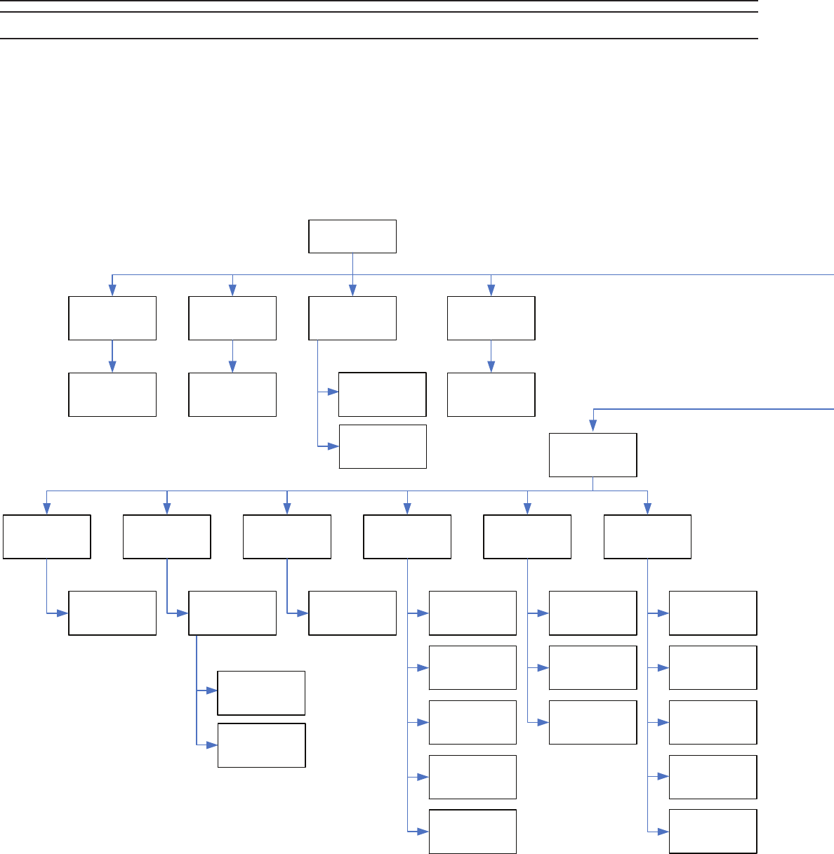
Pg. 26 BLUE BOX Series Operations and Maintenance Manual
LCDBBO&M0M04Mar08
DTC REFERENCE GUIDE
User Menu
Manual Override
Page 28
Review Schedule
Page 28
Group Loads
Page 28
Program Switch
Page 29
Remote System
Menu
Owner Settings
Page 31
Relay Properties
Page 29
Panel/Switch Types
Page 29
Addressing-
Bus Scan
Erase options
Restricted
(Password 90001)
Manual Control Schedules Maintain + Timer Program
Buttons Triggers
Auto Addressing
Page 31
Read Address
Page 32
Dial up Host
Page 33
Remote Password
Page 33
Local Network Dial
Page 33
Erase by Address
Button
Page 33
Default Names
Page 34
Erase Relay
Boards
Page 34
Addressing Relay Parameters
Page 30
Owner Name
Settings
Bus Scan Display
Page 32
Erase Clock
Memory
Page 34
Erase By
Address
Error Statistics
Page 32
More Diagnostics
Page 33
Board Settings
Page 31
Extra Address
Set Up
Maintain + Blink
Your digital lighting control system offers many sophisti-
cated features, including editable sequencing, and timer
values for each relay. Use this Flow Chart to navigate to
any of the screens shown below.
Some clock screens are used for navigation and some for
editing schedules, switches, photocells, relays and more.
For more information about any of the screens, go to the
page on the box.
28
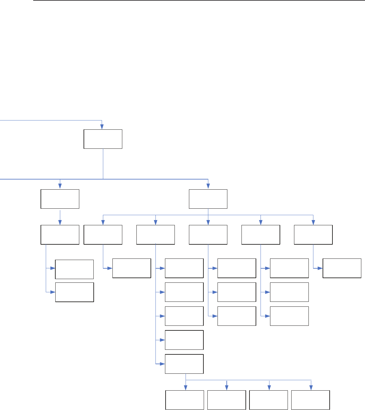
Pg. 27
LCDBBO&M0M04Mar08
Setup Menu
System options Addressing-
Bus-Scan
Edit Holidays
Page 34
Set Time and Date
Page 34
Select Location
Page 35
Daylight Setup
Page 36
Naming Menu
Page
Display options
Page 35
Keyboard Lock
Code
Page 35
Group Names
Page 36
Schedule Names
Page 36
Switch-Button
Names
Page 37
Panel-Load Names
Page 37
Relay Parameters
Page 30
Time and DateHoliday List 1
Holiday List 2
Auto-Addressing
Page 31
Read Address
Page 32
Bus Scan Display
Page 32
WHAT and WHEN?
Scheduled Events
Page 37
What Controls
Groups
Page 37
What Controls
Relays
Page 38
System
Menu Setup
Relay Properties
Page 29
Board Settings
Page 31
Extra Address
Set Up
29

Pg. 28 BLUE BOX Series Operations and Maintenance Manual
LCDBBO&M0M04Mar08
Manual Override Screen
The manual override screen allows for manual control and
visual indication of the status (on/off) of any relays in any
panel.
Auto/Hand Indicator
Load Selection
Status Indicator
LCP Selection
Relay ID
MANUAL CONTROL AU
LCP - 1 LOAD - 1
1■ 3■ 5■ 7■ 9- 11- 13- 15-
2- 4- 6- 8■ 10- 12- 14- 16-
To view different panels on the system:
TAB to LCP Selection. SCROLL to cycle through all the
relay panels that are connected to the system and view the
status of their relays or zones.
To turn a specifi c relay or zone off and on:
Once you have selected the relay panel, TAB to high-
light the Load Selection. SCROLL up or down to select
the relay you wish to control. Press ENTER to toggle the
LOAD (relay or zone) “off” or “on.” When the relay is “off,”
a hyphen will be displayed next to the Relay ID. When the
relay is “on,” a solid rectangle will be displayed.
Checking to see if a panel is in Hand mode:
The Auto/Hand indicator (see diagram above) indicates if
the panel is in Auto or Hand mode. “AU” indicates the LCP
is in Auto mode. “MN” indicates Hand mode.
Review Schedule Screen
Set and edit the time schedules.
SCHEDULES PAGE 1-6
NAME: SCHEDULE 1
SCH 1 ==> NO LOADS
SCH 2 UNUSED
SCH 3 UNUSED
SCH 4 ==> GROUP 4
SCH 5 UNUSED
SCH 6 ==> DISABLED
Schedule 1 is
programmed and
has no loads
Schedule 3 is not
programmed
Schedule 4 is
programmed and
controls GROUP 4
Schedule 6 is
programmed, but is
disabled
NOTE: There are 6 pages of schedules – 32 sched-
ules total. To switch between pages, TAB UP or TAB
DOWN to the Page Selection Field and SCROLL UP
or SCROLL DOWN to switch between pages.
To create or review a schedule:
TAB DOWN until the correct Schedule Name is selected
and press Enter. See section on Time Schedules for com-
plete instructions on how to choose the correct kind of
schedule and set it up.
To disable a schedule:
TAB UP or TAB DOWN until the correct Schedule Name
is highlighted, and then press SCROLL DOWN to dis-
able the schedule (the Group Selection will change to say
DISABLED). Press SCROLL UP to re-enable it.
To assign or change the group schedule controls:
TAB UP or TAB DOWN to the Group Selection for the
desired schedule. Press SCROLL UP or SCROLL DOWN
to change which group is selected.
Group Loads Screen
The Group Loads screen is used to designate groups of
relays, change how they are controlled and directly turn
groups on and off.
NOTE: There are 6 pages of groups – 32 groups total. To
switch between pages, TAB UP or TAB DOWN to the Page
Selection Field and press SCROLL UP or SCROLL DOWN
to switch between pages.
GROUPS PAGE 1-6
GROUP 1 UNUSED OFF
GROUP 2 UNUSED OFF
GROUP 3 USED MOM
GROUP 4 USED ON
GROUP 5 USED ON
GROUP 6 UNUSED OFF
This group does not
have any loads
Momentary Group
This Group has loads
and is on
TAB to a group and
SCROLL up or down to
change the status
Enter to edit the group
To create or edit a group:
TAB DOWN to the Group Name you want to create or
edit and press ENTER. Note that the Group Usage field
directly to the right of the name indicates if the Group has
already been defined (USED) or has not yet been defined
(UNUSED). For more detailed information, see the section
on programming groups.
To change how the relays in a group are controlled:
TAB UP or TAB DOWN to the Group Name and press
ENTER. Use SCROLL UP and SCROLL DOWN to change
the type of group. See the section on programming groups
for more information. Press EXIT to save your change and
return to the Group Loads screen. Notice that the Group
Status will now reflect the change that you made.
To turn a group on or off directly:
TAB DOWN to the Group Name you want to control. If it
is a MAINTAIN-type group, the Group Status will indicate
that the group is either ON or OFF. With the Group Name
selected, press SCROLL UP to turn the group ON, and
press SCROLL DOWN to turn the group OFF.
If the selected group is a MOMENTARY-type group
(MOMENTARY ON, MOMENTARY OFF, MOMENTARY
MIX,) the Group Status will display as MOM. With the
30

Pg. 29
LCDBBO&M0M04Mar08
Group Name selected, press SCROLL UP to activate the
group. If it is a MOMENTARY ON group, the relays will
turn ON. If it is a MOMENTARY OFF group, the relays will
turn OFF when you press SCROLL UP. In a MOMENTARY
MIX group, the relays will turn ON or OFF depending on the
group settings when you press SCROLL UP.
Program Switch Screen
The Program Switch screen allows you to set and review
programming for switches, dry contact inputs and photo-
cells.
NOTE: There can be several pages of switches avail-
able for programming. To switch between pages,
TAB UP or TAB DOWN to the Page Selection Field
and press SCROLL UP or SCROLL DOWN to switch
between pages.
SWITCHES PAGE 1-2
#3: 14 BTN SW 3
#4: SWITCH 05
#5: SWITCH 06
#7: SWITCH 07
#8: SWITCH 08
#11: SWITCH 11
#12: SWITCH 12
Blue Box Contact
Switch Inputs will
display as a 14 Button
Switch.
Switches and Switch
Inputs can be named
(see naming section)
Only IDs that are
assigned to Switches
will display on this
screen.
Setting or reviewing programming for a switch:
TAB DOWN to the switch, photocell or dry contact input
you want to program. They are listed by address. Press
ENTER to access the programming screen for the device.
See the Basic Programming section of this manual for
complete instructions on programming different devices.
Panel Switch Types Screen
The PANEL/SWITCH TYPES screen is used to define
what type of device is at each address. Devices are either
Panels, Switches, or Analog/Digital inputs.
It is very important that the correct device type is specified
for each address on this screen. Otherwise, the system
will not know the location of programmable switches, con-
trollable relay panels, etc.
Selecting a Device Type
TAB to the Device ID as displayed on the left side of the
screen. Once selected, use the SCROLL UP and SCROLL
DOWN buttons to change the Device Type selection.
NOTE: There are 19 pages of addresses you can specify
devices for – 127 addresses total. To switch between
pages, TAB to the Page Selection Field and SCROLL to
switch between pages.
More Information
The PANEL/SWITCH TYPES screen is used in conjunc-
tion with the BUS SCAN DISPLAY screen. For each
address that is shown as being occupied on the BUS
SCAN DISPLAY, a corresponding device specification must
be set on the PANEL/SWITCH TYPES screen.
ADDRESSING PAGE 1-19
ID1 : 2408 AS LCP1
ID2 : 2408 AS LCP1
ID3 : 14 BTN SW
ID4 : 2 BTN SWITCH
ID5 : 2 BTN SWITCH
ID6 : ANALOG/DIGI 6
ID7 : 4 BTN SWITCH
The BUS SCAN and the PANEL SWITCH TYPES screens
must match each other. If a device is on the Bus Scan it
must also be defined in PANEL/SWITCH TYPES screen.
Conversely if a device is no longer on the BUS SCAN
(displayed as “0”) it must also be deleted out of the PANEL
SWITCH TYPES SCREEN. To delete a device from the
PANEL/SWITCH TYPES, SCROLL to NOT USED.
If devices are assigned to certain addresses on the
PANEL/SWITCH TYPES screen, and the system does not
detect anything actually connected at those addresses (as
shown on the BUS SCAN DISPLAY screen), errors will be
generated by the system.
For complete instructions on setting up a bus using the
PANEL/SWITCH TYPES screen and the BUS SCAN
DISPLAY, see the System Startup Guide that came with
your relay panel.
Relay Properties Screen
The RELAY PROPERTIES SCREEN and its sub-screens
allow you to make changes to settings that affect individual
relays.
RLY PARAMS PAGE 1-1
BOARD 1 DLY: 1
BOARD 2 DLY: NA
BOARD 5 DLY: 60
BOARD 6 DLY: NA
Each relay panel uses
two addresses. Boards
1 & 2 are one LCP
occupying address IDs
1 & 2. Boards 5 & 6 are
also one LCP.
1/60 second delay
between relays during
a sweep
Does not apply
1 second delay
between relays during
a sweep
The RELAY PROPERTIES screen itself displays one or
more pages of Board Addresses. These are the addresses
of the various relay control cards. Each control card will
occupy 2 board addresses, one for every 8 relays.
Say, for example, you have a relay panel, LCP 2, installed
at address #5. The control card will occupy addresses #5
and #6 on the BUS SCAN DISPLAY and PANEL/SWITCH
types. On the RELAY PROPERTIES screen we are dis-
cussing here, you will see it appear as BOARD 5 and
BOARD 6. The first eight relays on the panel would be
controlled by BOARD 5, and relays 9-16 would be con-
trolled by BOARD 6.
The RELAY PROPERTIES screen also shows the Delay
Setting for each Board Address. The delay refers to how
long a time interval will be inserted between one relay turn-
31

Pg. 30 BLUE BOX Series Operations and Maintenance Manual
LCDBBO&M0M04Mar08
ing on and the next. This is used when turning on a group
of relays at the same time – using a delay will “stagger” the
relays turning on so that the first relay in the group turns
on, then there is a delay, then the next relay in the group
turns on, then there is a delay, then the next relay in the
group turns on, etc. This is usually used for certain equip-
ment that must be turned on in a specific order, such as an
audio pre-amplifier being turned on before an amplifier.
This delay is measured in 60Hz cycles. The formula for
calculating the delay in seconds is:
Delay Setting divided by 60 = Number of seconds of •
delay between relays
So if your Delay Setting is DLY: 90, there will be 1½ •
seconds delay between relays turning on in that panel
(90 divided by 60 = 1½).
Changing the Delay Time
To change the Delay Setting for a specific control card,
TAB DOWN to the first Board Address of the panel you
want to change the setting for. With the Board Address
highlighted, press SCROLL UP and SCROLL DOWN to
change the Delay Setting for that control card. The second
address will always show “NA.”
Accessing Relay Settings
To access additional relay setting in the RELAY SETTINGS
sub-screen, TAB DOWN to the Board Address that con-
tains the relays you want to modify and press ENTER.
Relay Parameters Screen
The RELAY SETTINGS screen allows you to change
the normally closed / normally open setting for individual
relays. It also lets you manually set whether a relay will
give a “blink warning” (flash the lights off and on briefly a
short time before going off at the end of the day, etc.) or
not. Lastly, it lets you access individual relays to change
further settings such as timers.
RLY PARAMS PAGE 1-1
BOARD 1 DLY: 1
BOARD 2 DLY: NA
BOARD 5 DLY: 60
BOARD 6 DLY: NA
Each relay panel uses
two addresses. Boards
1 & 2 are one LCP
occupying address IDs
1 & 2. Boards 5 & 6 are
also one LCP.
1/60 second delay
between relays during
a sweep
Does not apply
1 second delay
between relays during
a sweep
Reading the Screen
Along the top of the screen are the numbers 1-8. Each of
these represents the Relay Number. If you are working
with a 16 relay panel at address #5, then BOARD 5 will
control relays 1-8 and BOARD 6 will control relays 9-16.
When you view the RELAY SETTINGS screen for BOARD
5, Relay Numbers 1-8 would correspond to relays 1-8 on
the panel. When you view the RELAY SETTINGS screen
for BOARD 6 however, Relay Numbers 1-8 will correspond
to relays 9-16, since those are the relays the board con-
trols. In this case, Relay Number 1 would control settings
for relay 9 on the panel, Relay Number 4 would control
settings for relay 12 on the panel, etc.
Further down on the screen is the Normally Closed Setting
for each relay. There are 8 spaces in this row, each lining
up with and corresponding to the Relay Number above it.
A dash ( – ) signifies that the relay is set to normally open.
A “Y” signifies that the relay is set to normally closed. The
default setting is “Y” – a normally closed relay.
The next row down is the No Blink Setting for each relay.
Again, there are 8 spaces in this row, each lining up with
and corresponding to the Relay Number above it. A dash
( – ) signifies that the relay will have a blink warning. A “Y”
signifies that the relay will not have a blink warning if it is a
MAINTAIN+BLINK group.
The next row down is the Sentry Switch Setting row. This
feature is not used.
Changing Settings
To change the Normally Closed Setting or No Blink Setting
for a specific relay, locate the Relay Number that cor-
responds with the relay you want to modify. Then TAB
DOWN to the Normally Closed Setting or No Blink Setting
that is lined up directly below the Relay Number. When
the setting is highlighted, press SCROLL UP or SCROLL
DOWN to change the setting between “–“ and “Y”.
Additional Relay Settings
You can access additional relay settings for any relay
by highlighting the Normally Closed Setting or No Blink
Setting for that relay and pressing ENTER. This will bring
up the MORE RELAY SETTINGS screen.
More Relay Parameters Screen
BOARD ID - 1 LOAD-8
INPUT TYPE: MOMENTARY
TIMER IS DISABLED
The MORE RELAY SETTINGS screen is where you can
set the timer for a relay and the blink warning time. A
“blink warning” is when the relays flash the lights off and
on briefly a short time before going off at the end of the
day, etc.
The first field on this screen is the Relay Input Type. This
feature is not currently used and should not be changed.
The next field is the Timer Setting field. This will either dis-
play “TIMER DISABLED” or the word “TIMER” followed by
a time setting, e.g. “TIMER 00:30:00”.
32

Pg. 31
LCDBBO&M0M04Mar08
If the Timer Setting field is enabled, then an additional field
will appear. This is the Blink Warning Setting. If the relay
is in a MAINTAIN+BLINK group, turning off that group will
cause the relay to flash the lights once, and then wait for
the amount of time specified in the Blink Warning Setting
before finally turning OFF.
To add a Timer to a relay:
The correct way to add a timer to a relay is to add the
relay to a MAINTAIN+TIMER group or MAINTAIN+BLINK
group and then adjust the timer in the group settings
screen.
To change the Timer setting on a relay:
In the RELAY SETTINGS screen, press TAB DOWN until
you have highlighted the numbers to the right of the word
“TIMER.” These show hours, minutes and seconds. Use
SCROLL UP and SCROLL DOWN for each number to
change the Timer amount to the value you want.
To remove a Timer from a relay:
Go to the RELAY SETTINGS screen and press TAB
DOWN until you have highlighted the word “TIMER.” Press
SCROLL UP or SCROLL DOWN to change this to “TIMER
DISABLED.”
To Change the Blink Warning Setting:
TAB DOWN to the number to the right of the text that says
“Blink Warning.” Use SCROLL UP and SCROLL DOWN to
change the value to the time you want.
Note on short timers: When using very short tim-
ers (less than 5 minutes), the “blink” warning timer
must be set to be less than the timer, even in
MAINTAIN+TIMER mode.
Board Settings Screen
RLY PARAMS PAGE 1-1
BOARD 1 DLY: 1
BOARD 2 DLY: NA
BOARD 5 DLY: 60
BOARD 6 DLY: NA
Each relay panel uses
two addresses. Boards
1 & 2 are one LCP
occupying address IDs
1 & 2. Boards 5 & 6 are
also one LCP.
1/60 second delay
between relays during
a sweep
Does not apply
1 second delay
between relays during
a sweep
These settings align
with relay 1
Highlight SETTINGs
and ENTER for more
properties
Highlight any of these
and ENTER for more
properties for Relay 8
BOARD 1 SETTINGS
1 2 3 4 5 6 7 8
NORMALLY CLOSED
Y Y Y Y Y Y Y Y
NO BLINK
Y - - - - - - -
SENTRY SWITCH
- - - - - - - -
Pressing ENTER on the word “SETTINGS” brings up a
screen that sets up a virtual relay panel, which can then be
used to disable individual relay timers in the board you are
editing.
This programming is only done by the factory and should
not be changed by the installer or user.
Owner Settings Screen
OWNER NAME SETTINGS
PLEASE ENTER THE NAME
TO BE DISPLAYED ON
THE OPENING PAGE.
LIGHTING CONTROL & DESIGN
This is where you can change the name that appears on
the first screen of the clock. TAB DOWN to the first space
and use SCROLL UP and SCROLL DOWN to change the
letter, number or symbol. Then TAB DOWN to the next
space and repeat until the desired name is filled in.
Auto Addressing Screen
No two devices can
share the same
address. Ensure you
select an unused
address!
Remember to SCROLL
to the address you
want to start with. The
screen will always open
with Address 1 even if
already taken.
START ADDRESS: 1
PRESS ADDRESS/ERASE
BUTTON OF ANY BOARD
TO ASSIGN THE ADDRESS
ABOVE TO IT.
THE ADDRESS WILL
THEN AUTO INCREASE.
The AUTO ADDRESSING screen is where you set the
address for any device on the bus. It consists of only one
field, the Address Selection.
Use the SCROLL UP or SCROLL DOWN keys to set the
Address Selection to the address you wish to assign to a
device. Then press the address button on the device itself.
This will do the following:
Erase the current address of that device and replace it 1.
with the number you set as the Address Selection.
Advance the Address Selection value up one or more 2.
addresses (depending on how many address spaces
were just assigned to the device).
A 16 relay panel takes two addresses for the relays and
one address for the contact inputs), so if you change the
Address Selection to 40 and then press the Address button
on the panel:
The panel is now assigned the addresses of 40 and 41, 1.
and
The Address Selection will advance TWO numbers up 2.
to 42, at which point you can continue addressing other
devices on the bus.
33

Pg. 32 BLUE BOX Series Operations and Maintenance Manual
LCDBBO&M0M04Mar08
Cautions:
If multiple devices share an address, they won’t work prop-
erly. For example, if a panel is assigned to addresses 10
and 11, and a switch on the same system is assigned to
address 11, there will be malfunctions with the switch, the
panel, or both.
Always check the BUS SCAN DISPLAY and make sure
an address is empty (represented by a “0” on the display)
before you assign that address to a device. Remember
that a panel with 16 relays will require TWO consecutive
addresses, so you would need to ensure that there are two
empty addresses next to each other on the BUS SCAN
DISPLAY before you assign them. The switch inputs on
the panel may be assigned consecutively, or at another
available location.
Read Address Screen
PRESS ADDRESS/ERASE
BUTTON OF ANY BOARD
TO READ IT’S ADDRESS
ADDRESS: 1
SERIAL #: D568
Press the Address
Button to see address
displays
The READ ADDRESS SCREEN allows you to check the
address of any device on the bus. There are no selectable
fields on this screen. To read an address, simply press
the Address Button located physically on any device. The
screen will then display the address and serial number of
that device.
Bus Scan Display
3300000000 0000000000
0000000000 0000000000
0000000000 0000000000
0000000000 0000000000
0000000000 0000000000
0000000000 0000000000
0000000 ERROR 0-04
The BUS SCAN DISPLAY shows what addresses on the
bus are being used by devices. It also indicates the gen-
eral type of device at each address (such as a switch or a
relay panel).
There are 127 Address Slots shown, each of which can be
occupied by the number 0, 1, 2, or 3. These slots are read
left to right, top to bottom like a book. So the first row cov-
ers addresses 1-20, the second row covers addresses 21-
40, etc. To make it easier to count, each row is separated
into two groups of ten Address Slots.
What do the numbers mean?
The number 0 in an Address Slot indicates that there is
no device using that address. The number 1 indicates a
switch or a photocell. The number 2 indicates an interface
card to a computer network. The number 3 indicates a
relay panel at that address.
How to use:
Use the BUS SCAN DISPLAY to
Verify that specifi c devices can be seen on the bus. For 1.
example, if you add a switch with an address of 15, you
should see a number “1” appear in Address Slot 15. If
you don’t there is either a cabling problem, the switch
isn’t actually set to address 15, or there is a problem
with the switch itself.
Locate empty addresses to use for adding new devices. 2.
If your new device is a relay panel, you will need to fi nd
TWO empty Address Slots (empty = displaying the num-
ber “0”) next to each other. For a switch or other device,
you only need to fi nd a single “0” Address Slot. Count
through the slots to fi nd the address of the empty one.
Use this address number on the AUTO ADDRESSING
screen to assign it to a new device.
For more information and procedure on addressing devic-
es using the BUS SCAN DISPLAY, see the System Startup
Guide that came with your panel.
What is the Error display on the bottom-right of the BUS
SCAN DISPLAY?
The Error Display is used by technicians to gather informa-
tion for correcting a malfunctioning system. You will not
need to use this field.
Error Statistics Screen
ERROR STATS. CLEAR
OVERALL: 10498
ADDR1: 0
CMD0: 0
EEPROM FLAG ERR: 0
EEPROM WRITE ERR: 0
DROP-OFF: 6
FATAL-ERR: 0
The ERROR STATISTICS SCREEN is used by technicians
for advanced troubleshooting of a system. The primary
cause of errors is flaws in the Cat. 5 cabling connecting
devices together, which creates problems for the different
equipment in sending and receiving signals.
The Clear Button is a field in the top right of the screen
that says “CLEAR.” To clear the errors that have been
recorded, TAB UP or TAB DOWN to this field and then
press the ENTER key.
Once errors have been cleared, there should not be more
than a few errors accumulating per hour. For more infor-
mation, see the System Startup Guide.
34

Pg. 33
LCDBBO&M0M04Mar08
More Diagnostics Screen
This screen is used by technicians for advanced trouble-
shooting of the system. You may need to use the last item
“Scan by Factory ID” to verify there are no dual addresses
on the bus.
Scan by Factory ID
This screen is to verify that there are no items on the
bus at the same address. Items at the same address will
sometimes work and sometimes not. They cause a bus to
be slow and unresponsive, and may make the clock reset
because it waits too long for a valid answer due to the con-
flicts caused by two items answering at the same time.
FACTORY ID-SCANNING
Hit ENTER to scan
for all times on
the bus, or EXIT to
quit.
Follow the instructions on the screen to verify and correct
any conflicts.
Dial-Up Host Screen
DIALING UP HOST
ENTER THE COMPLETE
PHONE NUMBER OF THE
HOST AND HIT ENTER.
13232261000
The DIAL-UP HOST SCREEN is used to connect the sys-
tem to a remote computer using the optional modem.
This option is rarely used, but can also provide a means
to test modem connectivity as detailed in the SYSTEM
HOOKUP GUIDE.
Remote Password
DIAL IN PASSWORD
IN HOST MODE THIS
IS THE REQUIRED
PASSWORD: 001900
Optional software exists which can be used to dial up
and access this lighting control system. The REMOTE
PASSWORD SCREEN is where you set the password that
must be used by a computer dialing in to access the sys-
tem.
The default is 001900. It is strongly recommended that you
do not change the default setting.
Local Network Dial
LOCAL NETWORK DIAL
REMOTE ADDRESSS: 01
There is an optional accessory (LAN-LINK card) that allows
multiple lighting control systems (for example, systems in
two separate buildings) to be connected together so they
can both be controlled by the DTC on either system.
If this accessory is installed, the LOCAL NETWORK DIAL
SCREEN is where you can choose to link into another con-
nected system and control that from your location.
You will most likely never use this screen.
Erase By Address Button Screen
WARNING !!!
WHILE ON THIS SCREEN.
PRESSING THE
ADDRESS/ERASE BUTTON
OF ANY BOARD WILL
ERASE BOARD MEMORY.
The ERASE BY ADDRESS BUTTON SCREEN allows
you to completely clear out the existing programming from
a switch, photocell, or relay control card. There are no
selectable fields on this screen.
To erase a device on the bus:
Navigate to the ERASE BY ADDRESS BUTTON SCREEN.
Physically go to the device you wish to erase all existing
programming for and firmly press the address button on
that device.
This will erase all button programming for switches, trigger
programming for photocells, and groups/relay properties
programming for a relay control card. The device will still
retain its address.
The address of the device you just erased will appear on
the screen to indicate that the operation completed suc-
cessfully.
Hard erasing devices:
You can also “hard erase” any device on the bus by hold-
ing its address button down for 20 seconds, regardless
of what screen is displayed on the DTC. However, be
cautioned that unlike using the ERASE BY ADDRESS
BUTTON SCREEN, the hard erase will also erase the
address of the device. In order to use that device again in
the future, it will need to be readdressed. See the section
in the System Startup Guide on addressing devices.
35

Pg. 34 BLUE BOX Series Operations and Maintenance Manual
LCDBBO&M0M04Mar08
Default Names Screen
WARNING ! BEFORE YOU
SELECT ‘YES’ PUT ALL
PANELS TO OVERRIDE
TO PREVENT LIGHTS
FROM TURNING OFF!
NO / YES
This screen has a single option. Select YES and press
ENTER to set all button, switch and group names back to
their defaults (e.g. “Switch#23”, “Group 1”, etc.).
If you do not wish to do this, select NO and press ENTER,
or simply press EXIT. This operation cannot be undone.
Erase Relay Boards Screen
ERASE ALL RELAY
BOARD MEMORY.
NO / YES
This screen has a single option. Select YES and press
ENTER to erase all memory from all the relay control cards
on the system. This will remove all group programming
and any changes to relay properties that have been made.
If you do not wish to do this, select NO and press ENTER,
or simply press EXIT. This operation cannot be undone.
Erase Clock Memory
ERASE ALL RELAY
BOARD MEMORY.
NO / YES
This screen has a single option. Select YES and press
ENTER to erase everything in the clock memory. This will
delete all schedules and all the settings in the PANEL/
SWITCH TYPES screen.
If you do not wish to do this, select NO and press ENTER,
or simply press EXIT. This operation cannot be undone.
Set Time and Date Screen
SET NEW TIME/DATE
12:00:00 PM
1 JUN 2010 MON
TIME STARTS WHEN
YOU... HIT ENTER
ASSEMBLED: 1 JAN 2005
This screen allows you to set the current time and date.
Use the TAB UP and TAB DOWN keys to highlight the
Hours, Minutes and Seconds as well as the Day, Month,
and Year. Use the SCROLL UP and SCROLL DOWN keys
to adjust the values as needed.
When you are done making adjustments, TAB DOWN to
the Confirmation Field (which is labeled “HIT ENTER”) so
it is highlighted, and then press the ENTER key. To cancel
without saving your changes, press the EXIT key at any
time.
Edit Holidays Screen
This screen is used to set certain days as holidays. These
holidays can then have special schedules applied to them
or can be omitted completely from normally scheduled ON
and OFF times.
There are two holiday lists. Any single schedule in the sys-
tem can have one alternate ON / OFF time for the days in
HOLIDAY LIST 1, and one for the days in HOLIDAY LIST
2. For more instructions on setting up holiday schedules,
please refer to the programming section of this manual.
SELECT HOLIDAY LIST
TO EDIT
HOLIDAY LIST 1
HOLIDAY LIST 2
The first screen prompts you to select HOLIDAY LIST 1 or
HOLIDAY LIST 2. Select the holiday list you want to edit
and press ENTER.
HOLIDAY LIST 1 - PAGE 1
NEW YEARS: NO
M.L. KING: NO
PRESIDENTS: NO
EASTER: NO
MEMORIAL: NO
INDEPENDENCE: NO
You will now see a list of holidays. TAB DOWN to each
one and use SCROLL UP or SCROLL DOWN to change
their setting to YES or NO. Holidays marked YES will be
included in the holiday list. Any special exception schedule
assigned to that holiday list will be applied to only the holi-
days within that list which are marked “YES.”
There are four total pages of holidays. Pages 1 and 2 con-
sist of preset holidays such as Thanksgiving and Easter.
Pages 3 and 4 have custom holidays that you can set for
any date. Use TAB UP and TAB DOWN to select the Day,
Month and Year, and use the SCROLL buttons to set their
values.
36

Pg. 35
LCDBBO&M0M04Mar08
Keyboard Lock Code Screen
KEYBOARD LOCK CODE
IS: 0000
SET CODE ‘0000’ TO
DISABLE OR ANY OTHER
CODE TO ENABLE KEY LOCK
PERMANENTLY
HIT EXIT IF NOT SURE
AND SEE USERS MANUAL.
This screen allows you to assign a password to the
DTC. Any user will need to enter this password in order
to access the menus and settings in the DTC and make
changes.
Setting the Code:
When you navigate to the KEYBOARD LOCK CODE
SCREEN, you will be prompted to create a 4-digit key-
board lockout code. Use SCROLL UP and SCROLL
DOWN to change values and TAB UP and TAB DOWN to
move between digits. When you have created the num-
ber you want, press the EXIT button to save the code and
return to the previous menu screen.
Any user attempting to access the programming interface
will now be required to enter the code you set in order
to view or change settings. Note: Exiting out to the first
screen locks the DTC.
Removing the Keyboard Lock Code:
To remove the Keyboard Lock Code, simply navigate back
to KEYBOARD LOCK CODE SCREEN, set the 4-digit
number back to 0000 and press EXIT.
Selection Location Screen
The SELECT LOCATION SCREEN allows you to set your
geographic location, which will then be used to calculate
the correct sunrise and sunset times for your schedules.
The first screen you will see displayed gives you the option
of defining your location using a major city in your region,
or by providing specific latitude and longitude values.
SELECT LOCATION
LIST OF CITIES
LATITUDE-LONGITUDE
Setting by City:
If you select the LIST OF CITIES option, you will be pre-
sented with the following screen:
LOS ANGELES, CA
LATITUDE: 34
◦
N
LONGITUDE: 118
◦
W
TIME ZONE: GMT-8
TO ACCEPT THE ABOVE
SETTINGS... HIT ENTER
Use the SCROLL UP and SCROLL DOWN buttons to
choose the nearest major city. When it has been selected,
TAB DOWN to the field that says “HIT ENTER” and press
the ENTER key to confirm.
If you do not want to apply your changes, press EXIT at
any time.
Setting by Global Coordinates:
If you selected the LATITUDE-LONGITUDE option, you will
be presented with the following screen:
LATITUDE: 34
◦
N
LONGITUDE: 118
◦
W
TIME ZONE: GMT-8
ACCEPT COORDINATES
BY ... HIT ENTER
TAB DOWN to each of the fields – LATITUDE,
LONGITUDE, and TIME ZONE and use the SCROLL UP
and SCROLL DOWN keys to set the correct values. The
“GMT” in the TIME ZONE field refers to “Greenwich Mean
Time”. Greenwich is a town in England which happens to
lie exactly on the 0 degree longitude line, and is therefore
is used as the value that other time zones are compared
to. GMT + 3 is the time zone 3 hours later than England.
GMT – 3 is the time zone 3 hours earlier than England.
Los Angeles is in the GMT – 8 time zone, 8 hours earlier
than England. New York is GMT – 5, three hours later
than Los Angeles, 5 hours earlier than England.
When you are done setting values, TAB DOWN to the field
that says “HIT ENTER” and press the ENTER key to confirm.
If you do not want to apply your changes, press EXIT at
any time.
Display Options Screen
MILITARY TIME: NO
SECONDS VISIBLE: YES
DAYLIGHT SAVINGS: YES
TEMPERATURE F/C: F
RS-232 K-BAUD: 57.6
MODEM MODE: 0
PHOTOCELL MODE: NEW
TO SAVE: HIT ENTER
This screen consists of various settings for the clock itself.
TAB DOWN to each setting and use the SCROLL UP and
SCROLL DOWN keys to change the value. An explanation
37

Pg. 36 BLUE BOX Series Operations and Maintenance Manual
LCDBBO&M0M04Mar08
of each setting is below.
MILITARY TIME – Can be set to YES or NO. If set to NO,
the clock will display the time in hours between 1 and 12
o’clock and use AM and PM to distinguish between day
and night. If set to YES, it will use Military or 24 hour time
and display hours between 0 and 23, with 12 being noon
and 0 being midnight.
SECONDS VISIBLE – Can be set to YES or NO. Controls
whether seconds are displayed on the main clock screen.
DAYLIGHT SAVING – Can be set to YES or NO. If YES,
then the time will be set forward and backward one hour
on the dates specified in the DAYLIGHT SETUP SCREEN.
If NO, then the clock will not automatically adjust itself for-
ward or backward an hour for Daylight Saving Time.
TEMPERATURE F/C – Can be set to either F (to display
the temperature on any connected thermostats in degrees
Fahrenheit) or C (to display the temperature on any con-
nected thermostats in degrees Celsius).
RS-232 K-BAUD – Can be set to a variety of numbers
between 2.4 and 115.2. This is the speed in Kbaud that
the DTC will communicate with a modem or computer that
is attached through the RS-232 connection. The default
value is 57.6.
MODEM MODE – Can be set to either 0 or 1. This is a
setting that is used by the factory for compatibility with cer-
tain cellular modems. It should always be set to 0.
PHOTOCELL MODE – Can be set to either NEW or OLD.
This setting is used to adjust the way photocells are read
by older pieces of hardware. It will be automatically set to
the correct value, which will almost always be “NEW.”
When you are done setting values, TAB DOWN to the field
that says “HIT ENTER” and press the ENTER key to con-
firm.
If you do not want to apply your changes, press EXIT at
any time.
Daylight Setup Screen
DAYLIGHT PARAMETERS
DAYLIGHT STARTS ON:
2ND SUN OF MAR.
DAYLIGHT ENDS ON:
1ST SUN OF NOV
The DAYLIGHT SETUP SCREEN allows you to set the
starting day and ending day for Daylight Saving Time. In
2007, the official Daylight Saving Time schedule changed,
and there is a possibility that it will change in the future,
which is why this screen exists in the DTC.
To change the settings:
TAB DOWN to select each field. SCROLL UP and
SCROLL DOWN to change the value. When you are done
setting the start and end dates, press EXIT.
The DTC will use the new values to set the system time
forward one hour on the starting day and backward one
hour on the ending day.
Group Names Screen
NAMES PAGE 1-5
NAMING GROUP 1
NAMING GROUP 2
NAMING GROUP 3
NAMING GROUP 4
NAMING GROUP 5
NAMING GROUP 6
NAMING GROUP 7
This screen allows you to assign your own names to the
Groups on the system. By default, groups are named
“Group 1,” “Group 2,” etc. You may want to create more
informative names such as “Sales Floor Lights” or “Parking
Lights.”
To do this, TAB DOWN to the group you want to change
the name for and press ENTER. A new screen will appear
with the current (usually default) group name.
Use TAB UP and TAB DOWN to switch between spaces
in the name and SCROLL UP and SCROLL DOWN to
change the letter, number or symbol in each space. Use
the delete button as needed.
When you are done, press EXIT to save the new name
and return to the GROUP NAMES SCREEN.
Schedule-Names Screens
NAMES PAGE 1-5
NAMING SCHEDULE 1
NAMING SCHEDULE 2
NAMING SCHEDULE 3
NAMING SCHEDULE 4
NAMING SCHEDULE 5
NAMING SECHDULE 6
NAMING SCHEDULE 7
This screen allows you to assign your own names to the
Schedules on the system. By default, schedules are
named “Schedule 1,” “Schedule 2,” etc. You may want
to create more informative names such as “Daily Staff
Lighting” or “Weekend Schedule.”
To do this TAB DOWN to the schedule you want to change
the name for and press ENTER. A new screen will appear
with the current (usually default) schedule name.
Use TAB UP and TAB DOWN to switch between spaces
in the name and SCROLL UP and SCROLL DOWN to
change the letter, number or symbol in each space.
When you are done, press EXIT to save the new name
and return to the SCHEDULE NAMES SCREEN.
38

Pg. 37
LCDBBO&M0M04Mar08
Panel-Load Names Screen
NAMES PAGE 1-1
NAMING LCP PANEL 1
NAMING LCP PANEL 2
NAMING LCP PANEL 3
NAMING LCP PANEL 4
NAMING LCP PANEL 5
This screen allows you to assign your own names to the
loads (relays) in the different panels on the system, as well
as name the panels themselves. By default, loads are
named “Load 1,” “Load 2,” etc. You may want to create
more informative names such as “Front Entrance Light” or
“Window Track Lights.”
To do this, first TAB DOWN to the panel you want to
rename, or which has loads you want to rename, and
press ENTER. You will now see a list of the different loads
on the panel, with the panel itself being the first item on the
list.
If you want to change the name of the panel, TAB DOWN
to highlight it on the list and press ENTER. Otherwise,
TAB DOWN to the load you want to edit the name for and
press ENTER. A new screen will appear with the current
(usually default) panel or load name.
Use TAB UP and TAB DOWN to switch between spaces
in the name and SCROLL UP and SCROLL DOWN to
change the letter, number or symbol in each space.
When you are done, press EXIT to save the new name
and return to the PANEL-LOAD NAMES SCREEN.
Switch-Button Names Screens
NAMES PAGE 1-1
NAMING SWITCH ID#5
NAMING SWITCH ID#7
NAMING SWITCH ID#11
NAMING SWITCH ID#22
NAMING SWITCH ID#24
NAMING SWITCH ID#33
NAMING SWITCH ID#47
This screen allows you to assign your own names to the
buttons on the different switches on the system, as well
as name the switches themselves. By default, buttons are
named “Button 1,” “Button 2,” etc. You may want to cre-
ate more informative names such as “Sign Light Toggle” or
“Front Office All Off.”
To do this, first TAB DOWN to the switch you want to
rename, or which has buttons you want to rename, and
press ENTER. You will now see a list of the different but-
tons on the switch, with the switch itself being the first item
on the list.
If you want to change the name of the switch, TAB DOWN
to highlight it on the list and press ENTER.
Otherwise, TAB DOWN to the button you want to edit the
name for and press ENTER. A new screen will appear
with the current (usually default) switch or button name.
Use TAB UP and TAB DOWN to switch between spaces
in the name and SCROLL UP and SCROLL DOWN to
change the letter, number or symbol in each space.
When you are done, press EXIT to save the new name
and return to the SWITCH-BUTTON NAMES SCREEN.
Scheduled Events Screens
ORDER OF EVENTS
PAGE 1-3 NEXT
MON G1 ON 9:00AM
MON G1 OFF 5:00PM
TUE G1 ON 9:00AM
TUE G1 OFF 5:00PM
WED G1 ON 9:00AM
WED G1 OFF 5:00PM
ORDER OF EVENTS
PAGE 2-3 NEXT
THU G2 ON 9:00AM
THU G2 OFF 5:00PM
FRI G2 ON 9:00AM
FRI G2 OFF 5:00PM
SAT G3 ON 9:00AM
SAT G3 OFF 5:00PM
The SCHEDULED EVENTS SCREEN is a listing of all the
on and off times contained in every schedule in the DTC,
sorted by day and time. It is useful for troubleshooting the
system in the event of lights turning on and off unexpectedly,
as it can identify an on or off time set in a schedule that may
have been forgotten about. It is also helpful in following the
exact sequence of lights turning on and off throughout the
week as a result of all the different schedules.
There are no settings that can be modified on this screen,
but there are usually several pages. Press SCROLL UP
and SCROLL DOWN to cycle through the different pages
and EXIT to leave the screen.
What Controls Groups Screen
WHAT CONTROLS
GROUP 1
HIT ENTER TO SCAN
THE SELECTED GROUP.
WHAT CONTROLS
GROUP 1
SCHEDULE 1
This screen is used in troubleshooting or programming to
determine what devices or schedules are turning specific
groups on or off.
A group can be turned on or off by a schedule, a photo-
cell, a switch, or by the dry contact inputs on a relay panel
(which are also considered a form of switch).
To get a listing of items that turn on or off a specific group,
TAB DOWN to the Group Selection and use the SCROLL
UP and SCROLL DOWN keys to set it to the group you
want and press ENTER.
The system will scan the bus and provide a list of items
which control the group you selected.
Note: there may be more than one page of items that con-
trol that group. If this is the case, then you can highlight
the page number using TAB DOWN and then view the
other pages using SCROLL UP and SCROLL DOWN.
39

Pg. 38 BLUE BOX Series Operations and Maintenance Manual
LCDBBO&M0M04Mar08
What Controls Relays Screen
WHAT CONTROLS
LCP-1 LOAD-1
HIT ENTER TO SCAN
THE SELECTED GROUP.
WHAT CONTROLS
LCP-1 LOAD-1
GROUP 1
SW 6 BTN2 TOGGLE
This screen is used in troubleshooting or programming
to determine what devices or groups are turning specific
relays (or zones) on or off.
A relay (or zone) can be turned on or off by a group, a
photocell, a switch, or by the dry contact inputs on a relay
panel (which are also considered a form of switch).
To get a listing of items that turn on or off a specific relay
(or zone), first TAB DOWN to the Panel Selection and use
the SCROLL UP and SCROLL DOWN keys to set it to the
panel which contains that relay. Then TAB DOWN to the
Load Selection and use SCROLL UP and SCROLL DOWN
to select the exact relay (or zone) and press ENTER.
The system will scan the bus and provide a list of items
which control the relay or zone you selected.
Note: There may be more than one page of items that
control that relay or zone. If this is the case, then you can
highlight the page number using TAB DOWN and then
view the other pages using SCROLL UP and SCROLL
DOWN.
SYSTEM INSTALLATION STEPS
SYSTEM INSTALLER
THESE 9 STEPS MUST BE COMPLETED:
This column gives an overview of all the steps necessary
to install a complete lighting control system.
Line voltage cabling can be made up at any time, but the
following should be done in sequence for the fastest instal-
lation.
Plan your cabling using the guidelines found in the sec-1.
tion “Cable Planning” before pulling any conductors or
making any connectors.This will save time and money.
Pull Cat. 5 in a daisy-chain to all digital devices. Crimp 2.
on RJ45 connectors.
Make crimps correctly (see Bus Connections section).
Test each cable with a LAN cable tester prior to plugging 3.
it into the bus.
Remote Cable Tester
Plug in the Cat. 5 once all cables are tested.4.
Test the system per the Activation Checklist section.5.
Make the remaining low voltage cabling connections for 6.
any contact closure devices or photocells.
Switch on the power supply for every active device (an 7.
“active device” has an onboard power supply) on the
bus. Voltage output should be about 12vdc from these
devices.
Check the LEDs on all devices to ensure that they are 8.
receiving power. If any devices are not powered up, see
the “Bus Scan/Error Statistics Tests and Trouble Shoot-
ing” section of this manual.
Do the required initial programming per the System 9.
Software Start-Up section.
Cable Planning
There are three types of cabling within this digital lighting
control system.
Digital devices are daisy-chained using Cat. 5 cable •
with RJ45 connectors. Use this Guide for Cat. 5 and
network wiring.
Some digital devices have low voltage inputs for con-•
tact closure devices or photocells. Refer to the individ-
ual Product Installation Guides for hook up details.
Line voltage cabling is required to power electronics •
in some devices and for the relays controlling loads.
Refer to the Product Installation Guides for details.
All digital devices have an RJ45 connector and are daisy-
chained using Cat. 5 cable (with RJ45 connectors). Do not
“home run” any of the digital devices on the bus back to a
relay panel. When cabling digital devices, no spurs or T-
Taps are allowed.
40

Pg. 39
LCDBBO&M0M04Mar08
If the above illustration were converted to a single line
drawing, it would look like this.
MASTER RELAY PANEL
WITH DTC CLOCK
DIGITAL
SWITCH
DIGITAL
SWITCH
DIGITAL
SWITCH
The saw-tooth pattern is a drawing standard which indi-
cates a daisy-chain style network (RS-485).
MASTER RELAY PANEL
WITH DTC CLOCK
DIGITAL
SWITCH
DIGITAL
SWITCH
DIGITAL
SWITCH
No Spurs No T-Taps
DIGITAL
SWITCH
DIGITAL
SWITCH
Eliminate Low Voltage Interference
Cat. 5 cable must be at least 12” from all line voltage con-
ductors, except to cross or make terminations. Cat. 5 cable
must be kept away from all EMF devices such as ballasts
or transformers.
Isolate Line Voltage Cable
photosensor
Low Voltage Cable
Relay Panel
PS
photosenso
r
input
relay
Line Voltage Cable
Low voltage cabling must not be run in parallel with line
voltage cable, and must not share the same conduit,
whether digital cable (Cat. 5) or low voltage cable (3#18
from a photosensor).
Isolate Line Voltage Devices
photosensor
Low Voltage Cable
Relay Panel
PS
photosensor
input
relay
12” or more
Ballast
Ballast
Line Voltage Cable
Low voltage cabling must avoid EMF or RF from ballasts
or other “noisy” loads. EMF or RF interference can create
an unstable bus and can eventually ruin digital devices.
Planning Your Cabling Route
There is a limit to how many switches and photocell cards
you can add in a row over long runs of Cat. 5 cabling. The
more feet of Cat. 5 cable used, the fewer bus-powered
devices you can daisy-chain together before needing to
add another relay panel or active device. If too many bus-
powered devices are added contiguously over long cabling
lengths, they may not receive enough current to operate.
Use the Bus Powered Devices chart to help plan your
cabling route by avoiding too many contiguous bus-pow-
ered devices.
41

Pg. 40 BLUE BOX Series Operations and Maintenance Manual
LCDBBO&M0M04Mar08
Defi nitions:
Active Device - Device with power supply (a transform-
er). It acts as a source of electrical energy for the bus.
Bus-Powered Device - Any device that relies on the
12v supplied by the bus for its power. Example: digital
switches and photosensor cards.
1000 ft
900 ft
800 ft
700 ft
600 ft
500 ft
3
6
9
12
Number of Bus Powered Devices
Total Feet of Cabling from One Active Devic
e
Not Allowed
Allowed
Bus-Powered Devices Allowed
For Each Active Device
Don’t Cause Voltage Drop!
Per the Bus Powered Devices chart, up to 3 bus-powered
devices may be powered across 1000 feet of Cat. 5 cable.
The active device may be located anywhere within the
1000 foot region.
$ $ $ $ $
power
active device
$
bus-powered devices
Up to 3 bus powered devices @ 1000 ft
power
active device
Up to 3 bus powered devices @ 1000 ft
active device anywhere
in the 1000 ft zone
Cat 5 Cable
Multiple active devices in the same location will not
increase the distance allowed.
$ $ $ $ $ $
1000 ft insufficient power
power
active device
bus-powered devices
power
active device
bus-powered devices
Cat 5 Cable
For the above scenario, the correct solution would be to
route the Cat. 5 properly so as to spread the active devic-
es out. This is in the next diagram.
$ $ $
1000 ft
power
bus-powered devices
power
sufficient power
$ $ $
Cat 5 Cable
RJ45 Connectors
Cat. 5 installation instructions
Never make “hot” RJ45 crimps (crimping the other
end of a cable that has been plugged into a powered
device). This can damage equipment and can cause
devices to re-address themselves.
Remove two inches of jacket, using a Cat. 5 Jacket 1.
Stripper
. Carefully inspect the conductors for nicks.
Un-twist each pair, and straighten each conductor between 2.
the fi ngers. Do not untwist into the inside of the jacket.
Reorganize the conductors into the order shown. Bring 3.
all of the conductors together, until they touch.
At this point, re-check the wiring sequence.4.
Cut all of the conductors at a perfect 90 degree angle 5.
from the cable at 1/2” from the end of the cable jacket.
This is a very critical step. The conductors must be
straight to guarantee contact.
Place an RJ45 plug on the end of the cable with the 6.
locking prong facing down.
Push moderately hard on the conductors so they con-7.
nect to the back of the plug.
Visually inspect the conductors to ensure that they are 8.
still in the correct order and the end of the jacket is
about 3/16” inside the plug.
42

Pg. 41
LCDBBO&M0M04Mar08
Using a ratcheting crimp tool, crimp the plug. Force 9.
the contacts through the insulation on the conductors.
Crimp 2 or 3 times for the best possible connection.
Visually inspect each connector for a proper connection. 10.
Contacts should be pushed into the insulation of each
conductor.
Repeat this process on the other end of the cable to cre-11.
ate a straight-through cable.
Test every cable for continuity with a LAN cable tester. 12.
While testing, wiggle and tug on each connector to
ensure a solid crimp. The primary issues with any net-
work-based product usually trace back to cabling. If the
cables do not pass, re-crimp.
Notes Regarding Making Category 5 Patch Cable
Have the following tools on hand when making up Cat. 5
patch cables: Ratcheting crimp tool, Cat. 5 Jacket Stripper
and a LAN cable tester that allows remote testing - the
ends of the cable will be remote from each other. A cheap
tool that saves a few dollars now can cost thousands later
.
RJ45 plugs are manufactured for solid conductors or
stranded conductors, or in some cases both. It is very
important to be sure the plug matches the conductor, or
that it is dual-purpose. Since they can be difficult to visually
distinguish, categorize and store each type carefully. Using
the wrong type has been found to cause intermittent con-
nections after the system is started up.
Contacts not seated properly.
Contacts seated properly.
Orange/White
Orange
Green/White
Blue
Blue/White
Green
Brown/White
Brown
Color code conforms
to Ethernet standard
568-B
ACTIVATION CHECKLIST
This copy of the System Start-Up Guide is included so that
you may refer to it when adding new devices to an existing
bus. Remember, this network should not exceed 16 digital
devices.
This Section can be used as the most basic trouble-shoot-
ing method for your lighting controls. When all other trouble-
shooting steps have failed to solve an existing system,
repeat the steps of the Start-Up Guide. The following tests
should be done before powering the system. Failing to do
these tests can cause additional work.
The suggested handlings for each test assume each previ-
ous test is successfully completed. For that reason it is
critical that each test is passed before moving on.
The most complex trouble-shooting issues almost always
pull back to bad cabling or other issues which would have
been handled in minutes had the the following tests been
done and any anomalies handled.
Continuity Test & Results
De-power every item on the bus, check the voltage at 1.
both ends for 0 volts and remove any terminators.
Active devices (with their own power supply) that do
43

Pg. 42 BLUE BOX Series Operations and Maintenance Manual
LCDBBO&M0M04Mar08
not have a dedicated breaker can be de-powered by
unplugging the secondary side of the transformer.
At one end of the bus, short Gnd to A and B to +12 us-2.
ing the Data/Power Jumper which is included with the
master panel.
Bus Checker
is added to
fi rst device
Data power
Jumper is
added to
last device
At the other end of the bus plug in the Bus Checker 3.
Card to the fi rst device on the bus.
Check resistance from Gnd to A and B to 12v. 4.
Check resistance from A to B.5.
Results for Measuring Gnd-A and B-12v
100 ft...................3-4 ohms
500 ft...............12-20 ohms
1000 ft.............34-40 ohms
2000 ft.............68-80 ohms
3000 ft.........102-120 ohms
4000 ft.........130-160 ohms
Continuity Test Results (G to A and B to 12)
Length/Resistance
The Gnd to A and B to 12 resistance readings are used to
calculate the length of the bus and both should be close to
the same value (within 5%).
Their value will be 34 to 37 ohms per 1000 feet, and
therefore should never exceed 160 ohms (4000 foot bus
limitation). Calculate what the estimated bus length is from
the resistance and compare it to the actual cable length.
For example if the bus was estimated to be 1000 feet the
resistance should be about 35 ohms.
If more than 5% different from each other or outside the
expected range, several possibilities exist:
Sometimes the B to 12 measurements become polar-1.
ized. Flip the test probes and check B to 12 again. If
the measurements match and are in range, the test is a
pass.
Crimps may have become resistive when the Cat. 5 was 2.
pushed into the wall or the bus connectors. For larger
buses, use the Bus Splitting Technique to locate this.
Cat. 5 cable may have been nicked when stripped or 3.
torn when pulled through conduit. For larger buses, use
the Bus Splitting Technique to locate this.
Re-check your test results. Sometimes, your meter 4.
is not properly set and can show funny readings. For
larger buses, use the Bus Splitting Technique to locate
this.
A bus connector may have become unseated from its cir-5.
cuit board (very rare) in a rough installation environment.
Results for Measuring A to B
1...................... 450 kOhms
2...................... 225 kOhms
5........................ 80 kOhms
8........................ 56 kOhms
10...................... 45 kOhms
16...................... 28 kOhms
Continuity Test Results (A and B only)
Length/Resistance
This measurement will indicate how many digital devices
are on the bus. It is also used to discover any shorts
between the A and B terminals.
Each digital device has a resistance of about 450 kOhms
across A&B terminals. Multiple devices will act like resis-
tors in parallel. Only digital devices should be included in
this calculation.
These values do not need to be exactly in line with the
chart but do need to be within range. If your A-B measure-
ments are completely out of range and the first portion of
this test is within range:
If the resistance is about 100 - 300 ohms, a terminator 1.
is present. Use the bus splitting technique to locate the
terminator.
If the resistance is less than 50 ohms, A and B are 2.
shorted together. For larger buses, use the Bus Splitting
Technique to locate the short.
1st Terminator Test & Results
Terminators short an onboard 120 ohm resistor across the
A & B terminals to prevent communications reflections. The
terminator must be located only at each end of the bus.
44

Pg. 43
LCDBBO&M0M04Mar08
The manifestations of a terminator in the middle of the bus
or a missing terminator from the ends of the bus are many:
switches will not work, lights will not turn off after hours,
the system will appear to work only sporadically.
If you see any of these manifestations, you can be certain
that the bus is not terminated or the cabling has issues.
Remove the Data/Power Jumper and on the same de-1.
vice plug in a Terminator.
Terminator (in blue) Terminator (in blue)
Go back to the beginning of the bus and measure resis-2.
tance for the terminals (see below) on the bus checker
card.
Measure across G to A and B to 12va.
Measure across A to Bb.
Results for Measuring A to B
The A to B results are the most critical for the First
Terminator Test
100 ft............................125
500 ft............................150
1000 ft..........................175
2000 ft..........................230
3000 ft..........................285
4000 ft..........................340
First Terminator Test Results (A to B only)
Length/Resistance
The A to B measurement indicates the distance from the
bus checker card (where you did the testing) to the ter-
minator (which should be on the other end of the bus).
Resistance will be about 50 - 55 ohms per 1000 feet, plus
120 ohms for the first terminator. This value should never
exceed about 350 ohms (indicates a 4000 foot distance
from the bus checker to the terminator).
Compare the calculated length from this test to the calcu-
lated cable length from the Continuity Test. They should
indicate a similar cable length. If not:
The terminator is not seated properly. Remove it and care-
fully remount it on the dual pin connector.
If too low, there are two possibilities: a) there is a short
somewhere on the bus or b) there is an additional termina-
tor in the middle of the bus.
Results for Measuring Gnd to A and B to 12v
These two measurements should be of the same general
value and should measure with a very high resistance -
MegOhms or “open line” depending on your meter.
If these values are very different or are not in range:
The data jumper cable has not been removed.1.
Sometimes the B to 12 measurements become polar-2.
ized. Flip the test probes and check B to 12 again. If
the measurements match and are in range, the test is a
pass.
Crimps may have become resistive when the Cat. 5 3.
cable was pushed into the wall or into the bus connec-
tors. Solve this using the bus splitting technique.
2nd Terminator Test & Results
Add the second terminator to the beginning of the bus1.
Measure: A to B (only).2.
Use the chart for reference:
100 ft..............................62
500 ft..............................67
1000 ft............................72
2000 ft............................78
3000 ft............................85
4000 ft............................90
Second Terminator Test Results (A to B only)
Length/Resistance
If your value is more than 10% out of range:
The second terminator is not seated properly. Remove it 1.
and carefully remount it on the dual pin connector.
45

Pg. 44 BLUE BOX Series Operations and Maintenance Manual
LCDBBO&M0M04Mar08
An additional terminator or bad connection is shorting 2.
some portion of the A and B terminals of the bus. Solve
this using the bus splitting technique.
Bus Splitting Technique
Remember to add, move or remove terminators or the 1.
data/power jumper to keep the measurements within
range.
On the middle device of the bus, disconnect one Cat. 5 2.
cable to effectively create two smaller busses.
Test each mini-bus to fi nd the out-of-range side.3.
Repeat steps 1 & 2 until the cable, crimp or device 4.
which is creating out of range measurements is located.
It is OK to check cables or devices by themselves if they
are suspect.
Inspect the RJ45 connectors: a crimp that tests OK may 5.
become resistive or shorted when pushed into a bus
connector or a junction box.
Re-check the cable with a LAN tester. A small nick on 6.
one conductor can become a break when the cable is
manhandled into its fi nal position.
If the crimps and the cable test OK, test the device and 7.
see if it is out-of-range without any cables attached. If it
is, inspect it for extra terminators, wire fragments on the
circuit board or for damage.
Bus Scan/Error Statistics Tests and Trouble Shooting
No programming, or other trouble shooting, should be
attempted over an unstable bus (See a,b and c below).
The bus is the communication line between all the panels,
switches and other devices in our system. When it is not
stable, messages or commands can be missed, ignored,
delayed, or corrupted, leading to completely unpredictable
results.
Even if everything is programmed and otherwise function-
ing correctly, an unstable bus can cause the system not to
work properly in “mysterious” ways.
Having completed the “Low Voltage Testing & System
Power-Up” checklist there is little likelihood of having Bus
Scan or Error Statistics issues.
Bus Scan
These are the three most important factors to consider
when looking at the BUS SCAN.
The BUS SCAN and the PANEL/SWITCH TYPES menu 1.
must match exactly. Everything on the bus scan is cor-
rectly defi ned under PANEL SWITCH TYPES and every
device listed under PANEL SWITCH TYPES is present
on the BUS SCAN.
Items should be stably displayed and NEVER appear 2.
and disappear or worse: just not present on the BUS
SCAN at all.
The Error Count should not increase more than once 3.
every three minutes.
To perform the BUS SCAN:
Follow this path:
USER MENU > SETUP MENU > SYSTEM SET UP 1.
MENU > RESTRICTED (Password: 90001) > AD-
DRESSING-BUS SCAN > BUS SCAN.
Verify that each device that is listed under the PANEL/2.
SWITCH TYPES menu is present.
Watch the screen for any device drop offs. There should 3.
be no drop offs.
Trouble-shoot any errors per the Trouble Shooting Sec-4.
tion.
Ignore the Error Counter on this screen. Go to the Error
Statistics Screen to check for errors.
Error Statistics Test
With a high error count, the system may appear to work
properly, but eventually the problem that is causing errors
will get worse and the digital device may cease to function
properly.
“Error count” measures the number of times the DTC tries
to communicate to a digital device but does not get a prop-
er response. If data is corrupted due to signal noise, the
digital device will ignore it. The DTC may attempt to broad-
cast a command thirty or more times if it does not receive
an acknowledgment. Each unsuccessful attempt is logged
as an error. Almost any system logs some errors over time
– usually a few errors per hour.
To check for Error Statistics
Follow this path: 1.
From the ADDRESSING BUS SCAN MENU:
TAB to ERROR STATISTICS and ENTER to select
or
From the Main Menu:
USER MENU > SETUP MENU > SYSTEM SET UP
MENU > RESTRICTED (Password: 90001) > AD-
DRESSING-BUS SCAN > ERROR STATISTICS.
TAB to CLEAR and ENTER to reset the error counter. 2.
Watch the display for three or four minutes. This test is 3.
a pass if all the error counts remain at zero or climb no
higher than one every three minutes.
Note: Sometimes the clock may automatically exit
programming mode if left too long. If this happens, just
46

Pg. 45
LCDBBO&M0M04Mar08
navigate back to the ERROR SCAN menu - the coun-
ter will continue to operate until CLEARED again.
Trouble-shoot any errors per the Trouble Shooting Sec-4.
tion.
Trouble Shooting
Quick Checklist
To solve Bus Scan or Error Statistics issues, check the fol-
lowing points first:
Verify low voltage connections. Has something become 1.
disconnected and not re-connected?
Check power supply for each device. 2.
Check for extra or missing Terminators.3.
Using the READ ADDRESS menu, check for and elimi-4.
nate any duplicate addresses. See the More Diagnos-
tics Screen instructions in the DTC Reference Guide
section of this manual.
To verify a specific step has solved the issue, re-scan the
bus. If the bus now appears stable during the scan and
error check, you have solved it.
If the above short list does not solve the problem, then
move onto the following comprehensive list of trouble
shooting procedures.
Check Connections
Verify the device is physically connected to the bus. 1.
Verify the RJ45 connectors are properly seated: Discon-2.
nect and then reconnect the RJ45s. Listen for a proper
“snap.”
Visually inspect that the contacts on the RJ45s are 3.
properly seated (not rounded off) per the RJ45 Connec-
tor Section of the System & Software Start-Up Guide
Re-check each Cat. 5 cable connection with a cable tes-4.
ter and during the test, twist and tug on the RJ45 con-
nectors to try and fl ush-out any intermittent connections.
Sometimes a cable reads OK but when pushed into a
wall box the contacts become unseated or a slightly
nicked cable fi nally breaks. This is easily handled by re-
crimping the RJ45.
If this is not a new installation, de-power all the devices 5.
on the bus and run the bus through the “Low Voltage
Testing & System Power-Up” checklist.
Check Power - Bus Powered Devices
If the device is bus-powered, verify that it does not 1.
exceed the limits of Bus Powered Devices Chart in the
System & Software Start-Up Guide (too far or too many
bus-powered devices).
Assuming the Chart values have not been exceeded,
check that each device is receiving enough Bus Power:
Add the Bus Checker Card to the bus at the device. If 2.
the LED lights up, there is enough power. Plug back
in the device. If its on line LED does not light up it has
failed.
If the LED on Bus Checker Card does not brightly light 3.
up you do not have enough voltage to power up the
device. Shorten your cable distance, or contact LC&D
for a Bus Booster.
Check Power - Active Devices
An active device (has its own power supply) will not report
if it is not powered-up properly. Do the following steps.
Verify it is powered-up. That the breaker is on; that the 1.
secondary side of the transformer is connected (it may
have been disconnected when testing the bus).
Verify that the power supply voltage matches the label 2.
on the power input lug (i.e. 120v to 120v).
Refer to the installation guides for each product to fur-3.
ther check power input.
Check Terminators
Check each device to see if an extra Terminator has 1.
been added.
Verify that there are Terminators on each end (fi rst and 2.
last devices) of the bus.
Check Address
Sometimes a device gets re-addressed or sometimes two
devices accidentally share the same address creating all
sorts of mysterious errors.
In the DTC Clock, navigate to READ ADDRESS. 1.
From the Main Menu:
USER MENU > SETUP MENU > SYSTEM SET UP
MENU > RESTRICTED (Password: 90001) > AD-
DRESSING-BUS SCAN > READ ADDRESS.
For digital switches press the fi rst button or the address-2.
ing button on the back. For all other devices press the
addressing button. An address will appear on the Read
Address screen.
Check that the address displayed agrees with the 3.
PANEL/SWITCH TYPES screen.
Any device that does not READ during this test should 4.
be disconnected from the bus and, using a Cat. 5
jumper cable, should be plugged directly into the master
panel and re-checked.
47

Pg. 46 BLUE BOX Series Operations and Maintenance Manual
LCDBBO&M0M04Mar08
If it still does not read, hard and soft erase the device 5.
several times and then try to readdress it using the
AUTO ADDRESS screen.
If it still does not read or will not address, it has probably 6.
failed.
Check Interference
Check to ensure that the Cat. 5 cable does not run near 1.
line voltage conductors, any dimmers or electronic bal-
lasts. EM or RF interference can cause signal degrada-
tion.
Disconnect contact closure switches or occupant sen-2.
sors or 0-10 voltage. The conductors to contact closure
switches or analog voltage devices can act like an FM
antenna and per the “Eliminate Low Voltage Interfer-
ence Section” of the System & Software Start-Up Guide
should never be run near power lines and if over 100 ft
long should be shielded.
SYSTEM SOFTWARE START-UP
Addressing and Defi ning Each Device
There are two steps that must be done to make all the
items on the bus work together. a) Assign an Address.
b) Define the Item in the PANEL SWITCH TYPES Menu.
Note that Master panels are pre-addressed and defined at
the factory. Only slave relay panels, switches and photocell
control cards require addresses and must be defined. Note
that a relay panel takes up two addresses.
Use the address planner in the back of this guide to
write in the addresses to be used. Sequential ad-
dresses are usually used but you may choose any
address up to 120.
In the clock display navigate to USER MENU > SETUP 1.
MENU > RESTRICTED (Password: 90001) >
AD-
DRESSING-BUS SCAN > AUTO ADDRESS.
Scroll the address to the fi rst one on your Address Plan-2.
ner and press the assign button or address button on
the relevant device. Note that the address number will
increment when the address has been assigned. Also
note that on slave relay panels you must fi rst assign the
relay panel by pressing the Assign Button and then the
switch inputs which have a separate address button on
the bottom right of the board.
Write the assigned address on each device with a per-3.
manent marker.
Now verify the address of each item by going to USER 4.
MENU > SETUP MENU > RESTRICTED (Password:
90001) > ADDRESSING-BUS SCAN > READ AD-
DRESS. Press the address button of each device and
check that the correct address comes up in the window
as per your address plan. Addresses can be written over
if incorrect.
On
l
in
e
RJ45
B
us Connectors
no
n
one
e
pho
p
hone
line
ne
Bus Connector
A
B
+
12
G
n
d
Au
t
o
H
a
n
d
C
ontact Closure Inputs
5
v
G
n
d
1
2
3
4
5
6
7
8
9
1
0
11
12
1
3
14
Terminator
H
an
d/
Auto Switc
h
Z
one
2
Z
o
n
e
4
Z
one
6
Zo
n
e
8
Z
on
e
1
Zo
n
e
3
Z
on
e
5
Zo
n
e
7
Assigns re
l
ays to a zon
e
Push "Assign" for 3 Seconds to check Mod
e
Assign
Bu
tt
o
n
g
Zo
n
es
1-
8
A
cti
ve
2
Z
ones
9
-1
6
A
ctiv
e
4
6
8
10
D
iscret
e
M
o
de
12
8
Z
o
n
e
M
od
e
1
4
16
Zon
e
M
od
e
16
1
3
5
7
9
11
1
3
15
J5
J
6
J7
O
ptiona
l
Inpu
t
A
dd
ress Assig
n
Zone
2
Zone
Zone
1
Zone
e
lays to a zone
s to check Mode
Assi
g
Butt
o
P
16
Optional Input
Address Assign
Lighting Control Panel
Record address of device
Digital Switch
Photocell Input Card
Contact Closure Card
Once a switch is mounted on the wall you may use
button 1 to check or readdress the switch.
Defi
ning Device Type
Once the device has been addressed, the system only
knows that it is a panel or a switch (not that it is a 6-button
switch, or an 8-relay panel) so the system must be told the
specific type of device that occupies each address (ID).
In the DTC Clock, navigate to PANEL/SWITCH TYPES1.
From Main Menu: USER MENU>SETUP MENU>
RESTRICTED (Password: 90001)>PANEL/SWITCH
TYPES
SCROLL to select
page number
ADDRESSING PAGE 1-19
ID1 :2408 as LCP1
ID2 :2408 as LCP1
ID3 :14 BTN SWITCH
ID4 :2408 as LCP2
ID5 :14 BTN SWITCH
ID6 :PHOTOCELL 3
ID7 :UNUSED
SCROLL to select
device type
TAB to move
cursor
Note: The master panel and it’s onboard inputs have
been entered at the factory. Additional items must
now be added.
TAB to “ID4” and SCROLL to select the Device Type 2.
(see below for a complete list).
T
AB to next UNUSED ID and repeat until every device 3.
is defi ned.
To select more pages, TAB to “PAGE 1-19” and 4.
SCROLL.
48

Pg. 47
LCDBBO&M0M04Mar08
EXIT to Main Menu when complete.5.
Device Chart:
Red indicates a variable. Any device can occupy any address.
Relay Panels must occupy three contiguous addresses. Any
digital device, including LCPs, can use any start address.
All Relay Panels occupy three
addresses. Each LCP should
be separately numbered
(LCP
1, LCP2 LCP3, etc.)
ID1: 2408 as LCP1
ID2: 2408 as LCP1
ID3: 14 BTN SWITCH
Digital Switches occupy one
address, but the number of
buttons must be defi ned:
ID12: 1 BTN SWITCH
ID13: 6 BTN SWITCH
Three Input Photocell Card:
ID7: ANALOG/DIGITAL
Bus Scan
Now that digital devices have been addressed and defined,
it is time to check the integrity of your digital bus.
The Bus Scan will help verify that all the previous steps
have been done correctly, and that each device on the net-
work is reporting properly.
In the DTC Clock, navigate to:1.
USER MENU > SETUP MENU > RESTRICTED (Pass-
word: 90001) >ADDRESSING BUS SCAN > BUS SCAN
DISPLAY
3313310110 11000000000
0000000000 00000000000
0000000000 00000000000
0000000000 00000000000
0000000000 00000000000
0000000000 00000000000
0000001 Err: 0-0
Device Address (ID#): 1
Device Type: 331
(8 or 16 relay panel)
ID#: 127
Type: 1
Error Counter
ID#: 30
Type: Not Used/Not Present
ID# 1-20
ID# 21-40
ID# 41-60
ID# 61-80
ID# 81-100
ID# 101-120
ID# 121-128
ID#: 12
Type: 1
(Digital Switch, etc.)
The Bus Scan Display shows the status of 127 device
addresses (ID#) starting at top left with ID#1. The sta-
tus of each ID# is represented by a numeral or series
of numerals:
If a 16 relay panel has a start address of “1”, 331 will
be displayed, starting at the top left position (addresses
1,2,3). The above “scan” shows this confi guration.
Item Bus Scan
Not reporting/not used 0
BLUE BOX relay panel 331 8 relays
331 16 relays
KnightsBridge (1-6)
Digital Switch 1
PCCS Card 1
Verify each address (device) is stably displayed on the2.
Bus Scan. Error count should not exceed more than
0-2 per hour. There must be a device defi ned in PANEL
/ SWITCH TYPES for every address that is shown as
used on the BUS SCAN DISPLAY. Addresses that are
shown as unused (“0”) on the BUS SCAN DISPLAY
must also be set as “UNUSED” in PANEL / SWITCH
TYPES.
Press EXIT to return to the ADDRESSING/BUS SCAN3.
MENU. Select the ERROR STATISTICS option and
press ENTER. Clear the current error counter by select-
ing the fi eld “CLEAR” and pressing ENTER. Watch
the error counts for at least 3 minutes. There should be
no errors of any kind accumulating within the 3 minute
period. If there are, you will need to proceed to the bus
correction steps in this manual.
Set Date & Time:
The DTC Clock in the relay panel is astronomical, and
needs to know the date, time, and location.
In the DTC Clock, navigate to: USER MENU > SETUP
1.
49

Pg. 48 BLUE BOX Series Operations and Maintenance Manual
LCDBBO&M0M04Mar08
MENU > SYSTEM SET UP MENU > SET DATE AND
TIME
ENTER NEW TIME/DATE
8:50:00 AM
27 Jun 2008 Fri
Time starts when
you ... HIT ENTER
ASSEMBLED: 3 Jan 2008
To save your settings
Tab to here and
ENTER to select
TAB to the “hour” and SCROLL to select. Repeat this2.
process for minutes, seconds, day
, month and year.
Tab to “HIT ENTER” and ENTER to save settings.
3.
Set Location:
In the DTC Clock navigate to: USER MENU > SETUP
1.
MENU > SYSTEM SET
UP MENU > SYSTEM OP-
TIONS > SELECT LOCATION > LIST OF CITIES
SCROLL
to select your city or the city nearest you.2.
Tab to “HIT ENTER” and ENTER to save settings3.
Detroit MI
Latitude: 42 N
Longitude: 83 W
Time Zone: GMT-5
To accept the above
settings...HIT ENTER
To save your settings
TAB to here and
ENTER to select
SCROLL to select
nearest city.
Optional: If you cannot find any cities within several hun-
dred miles of your location, EXIT and go to LATITUDE
- LONGITUDE. Use a dependable resource (internet, etc.)
to locate your exact Latitude and Longitude.
The
Time Zone is the number of hours negative or posi-
tive from Greenwich Mean Time (GMT). For example: the
North American Eastern Time Zone is -5 GMT, Central
Time is -6, Mountain Time is -7, Pacific Time is -8, and
Hawaii is -11.
To Disable Daylight Savings Time (only for regions not par-
ticipating in daylight savings time):
In the DTC Clock navigate to:
1.
USER MENU > SETUP
MENU > SYSTEM SET UP
MENU > SYSTEM OPTIONS > DISPLAY OPTIONS
TAB to Daylight Savings and SCROLL to select NO
2.
T
ab to “HIT
ENTER” and ENTER to save settings3.
Exit to Main Menu when complete.4.
Now that all parts of the bus are reporting and are on line
each of the items must be programmed to do it’s job. There
are three main programs.
Program a switch button•
Program a schedule•
Program a photocell•
50

Pg. 49
LCDBBO&M0M04Mar08
ADDRESS PLANNER PAGE
(Cross out items not used and write in address for items on your bus)
Factory Set:
ID #1&2
LCP 1
Factory Set:
ID #3
Contact Inputs
Master
Panel
ID # _____
& # _____
ID # _____
Slave
Panel
LCP 2
Contact Inputs
ID # _____
& # _____
ID # _____
Slave
Panel
LCP 3
Contact Inputs
ID # _____
& # _____
ID # _____
Slave
Panel
LCP 4
Contact Inputs
ID # _____
& # _____
ID # _____
Slave
Panel
LCP 5
Contact Inputs
14 Input Contact Closure
ID # _______
14 Input Contact Closure
ID # _______
14 Input Contact Closure
ID # _______
___________
Button Switch
ID # _____
___________
Button Switch
ID # _____
___________
Button Switch
ID # _____
___________
Button Switch
ID # _____
___________
Button Switch
ID # _____
___________
Button Switch
ID # _____
RELAY PANELS
SWITCHES
PHOTOCELL INPUT CARD/CONTACT CLOSURE INPUTS
3 Input Photocell Card
ID # _______
51

Pg. 50 BLUE BOX Series Operations and Maintenance Manual
LCDBBO&M0M04Mar08
52

Pg. 51
LCDBBO&M0M04Mar08
53

LCDBBO&M0M04Mar08
WARRANTY
Lighting Control & Design Inc. warrants each new unit for 36 months from date of shipment to
be free of defects in material and workmanship under conditions of normal use and specifi ed
ambient temperature when installed and operated under LC&D’s product specifi cations and in
accordance with the National Electrical Code.
LC&D shall at its option, repair or replace any defective unit which in its opinion, has not been
improperly installed, wired, insulated, used or maintained, provided however that LC&D shall
not be required to remove, install or re-install any defective unit and provided that LC&D is
properly notifi ed of said defect within the aforementioned warranty period. This warranty in no
way covers any labor required to effect changes.
Additionally, LC&D shall also replace any relay that fails within the fi rst 36 months under a “no
questions asked” exchange policy.
The foregoing warranty and optional remedies are exclusive and, except for the foregoing
warranties THERE ARE NO OTHER WARRANTIES OF MERCHANTABILITY OR OF ANY
OTHER TYPE. In no event shall LC&D or any other seller be liable for consequential or spe-
cial damages, nor for any repair work, undertaken without its prior written consent, nor shall
LC&D’s liability on any claim for damages arising out of or connected with the manufacture,
sale, installation, delivery or use of said unit ever exceed the price paid therefore.
905 Allen Avenue, Glendale CA 91201
323.226.0000, 800.345.4448, fax 323.226.1000
www.lightingcontrols.com
Lighting Control & Design
100% Digital Lighting Controls for Any Application
54

CHELSEA DIGITAL SWITCH
ADVANCED PROGRAMMING GUIDE
55
CONTENTS
1. Overview…………………………………………………………………… Page 1
2. Important Programming Notes …………………………………………….. Page 2
3. The Switch Setup Screen (First Screen) …………………………………….Page 3
a. 7 On = ______ …………………………………………………….. Page 4
b. 8 On = ______ ………………………………………………….…. Page 5
c. BTN Beep …………………………………………………….……. Page 6
d. Button 1 Address .…………………………………………….……. Page 6
e. 9-14 disable 1-6 ……………………………………………………. Page 7
f. Debounce …….……………………………………….……………. Page 7
4. The Switch Setup Screen (Second Screen) ………………...…………….... Page 9
a. ALL-OFF logic except groups ……..…………………………...…. Page 9
b. LED logic for other buttons ……………..……………………….. Page 10
5. The Button Edit Screen ………………………………………….……….. Page 11
a. LED mode ………………………………………………….…….. Page 11
b. Toggle mode …………………………………………..…….….… Page 12
c. Debounce …………………………………………….…….…..…. Page 12
6. Common Applications …………………………………………………… Page 13
a. How do I disable a particular switch button? ………………… Page 13
b. How do I set a button to give an audible “error” beep when
someone presses a disabled button? …………...................….…. Page14
c. How do I make a switch give an audible alert during a blink
warning period? ………………………………..…………...……Page 15
d. How do I set up a room with a partition, so that the switches
change their function depending on whether the partition is open
or closed? ………………………………………………………… Page 17
56

Overview
The Chelsea Digital Switch has been updated with several new programmable features.
In summary, they are:
•
Audible beep alert which can be used to notify users during a blink warning period before the
lights shut off. The beep pattern is programmable and can also be used by Tech Support to
help the customer locate a specific switch on the bus.
•
Programmable Locator LED. Now the LED at the top of
the switch can be programmed to flash during a blink
warning. It can also be activated by Tech Support, for use
in helping the user identify a particular switch.
•
Adjustable debounce time. Debounce is how long a switch
button must be held down before it is recognized as a button
press. Debounce can be set for the whole switch, or button by
button.
•
Alternate button programming. Chelsea Digital Switches can now have two sets of programming
for six buttons, or three sets of programming for three buttons. Each set of programming can be
activated by a time schedule, override switch, etc. This feature is useful for setting buttons to
function differently at different times of day, or in partitionable rooms where a switch functions
differently depending on whether a partition is open or closed.
•
Status LED logic is now programmable. The Status LED
above each button can now have one of 4 types of logic
used to determine whether it should be lit or not. For
example, if a button control 6 relays, and 4 of them are
ON, the user can set whether the LED will be ON or
OFF. This logic can be assigned button-by-button or for
all the Status LEDs on the switch.
•
Programmable Toggle logic. If a button controls multiple relays, it is important to synchronize
them when toggling them all at once. If some of the relays are ON and some are OFF, it is now
possible to
specify whether the switch syncs them all ON or all OFF when toggling.
•
The feature allowing button 1 of the switch to
function as the Address button can now be
enabled or disabled in the programming menu.
•
Enabling and disabling individual switch buttons is still an available feature carried over from the
previous version of the Chelsea. Enabling and disabling buttons can now be allowed or not
allowed for a switch in the programming menu. Additionally, disabled buttons can be set to
trigger a rapid series of beeps when pressed, so the user knows that the button has specifically
been disabled by programming.
- 1 -
57

! Important Programming Notes !
To use the advanced features of the new Chelsea Digital Switch, please ensure the
following:
• Always set a Chelsea Digital Switch as a “14 Button Switch” in the Panel/Switch
Types screen. This is true even if the switch only has 1, 2 or 3 physical buttons.
The reason for this is because advanced programming requires setting parameters
for buttons 7-14, even though they are “virtual” buttons and not physically present
on the switch.
• To access advanced programming functions of the Chelsea Switch, you must have
DTC clock version 4.48 or later.
• To use advanced programming functions of the Chelsea Switch, you must be
using switch firmware 1.12 or later. The version of firmware a switch has is
displayed in the lower left corner of the SETUP screen for that switch.
- 2 -
58

The Switch Setup Screen
(First Screen)
To access the screen, navigate to the switch you want to program, highlight the word
SETUP and press ENTER.
USER MENU → PROGRAM SWITCH → SWITCH# → SETUP
The Switch Setup Screen has a number of parameters which can be set as shown
below.
- 3 -
59

Table 1.1
7 ON = _____________
This field determines what happens when the LED status light associated with
Button 7 is turned ON.
Generally if the button is set to ON MODE and the relay it controls is
ON, the LED will turn ON as well. This also applies to the opposite
mode: if the button is set to OFF MODE and the relay it controls is OFF,
the LED will also generally turn ON (the only exceptions are if the logic
of the Status LEDs are changed as described later in this guide).
Note that there is no physical Button 7 or physical Status LED for Button 7 on a
Chelsea Digital Switch. So Buttons 7-14 are virtual buttons used for
programming purposes only, and the associated Status LEDs are also just virtual
placeholders that are turned on and off. Usually, virtual Buttons 7 and 8 will be
set to operate a spare relay or an empty relay position rather than a relay with a
connected load.
Possible Values Result
Normal
(default value)
None. Setting this value to “Normal” in a Chelsea Digital
Switch means that nothing will happen when the virtual
LED associated with Button 7 is turned ON.
BTS 1-6 < 9 - 14 When the virtual LED associated with Button 7 is ON, the
programming for buttons 1-6 will be replaced with the
programming for buttons 9-14. When the LED is OFF,
buttons 1-6 will revert to their original programming.
BTS 1-3 < 9 - 11 When the virtual LED associated with Button 7 is ON, the
programming for buttons 1-3 will be replaced with the
programming for buttons 9-11. When the relay is OFF,
buttons 1-3 will revert to their original programming.
BEEP When the virtual LED associated with Button 7 is ON, the
switch will make a beeping sound. Highlighting the word
BEEP and pressing ENTER will allow you to set the beep
pattern.
Locator When the virtual LED associated with Button 7 is ON, the
switch’s Locator LED will flash. Highlighting the word
Locator and pressing ENTER will allow you to set the
flash pattern.
Disable 1-6 When the virtual LED associated with Button 7 is ON,
buttons 1-6 will be disabled.
Disable 1-14 For a Chelsea Switch, this has the same effect as “Disable
1-6”. However, when programming a Digilink, it allows
all Digilink inputs (1-14) to be disabled.
Beep + Locator When the virtual LED associated with Button 7 is ON, the
switch will make a beeping sound and the Locator LED
will flash. Highlighting the words Beep + Locator and
pressing ENTER will allow you to set the beep and flash
pattern.
- 4 -
60

Table 1.2
8 ON = _____________
This field determines what happens when the LED status light associated with
Button 8 is turned ON.
The operation of this field is almost identical in operation to the “7 ON = __”.
The parameters are the same as those given in Table 1.1 above with a few
exceptions noted below.
In general, the BTS 1-6 < 9 – 14, BEEP, Locator, and Disable 1-6 functions
assigned to “7 ON = __” take priority over their “8 ON = __” counterparts.
For example:
If a switch is set to “7 ON = BEEP” and “8 ON = BEEP” and both virtual LEDs
are ON, the switch will have the BEEP pattern of “7 ON = BEEP” not the
pattern of “8ON = BEEP”.
If a switch is set to “7 ON = LOCATOR” and “8 ON = BEEP” and both virtual
LEDs are ON, the switch will blink the Locator LED and also beep.
Possible Values Result
Normal
(default value)
None. Setting this value to “Normal” in a Chelsea Digital
Switch means that nothing will happen when the virtual
LED associated with Button 8 is turned ON.
BTS 1-6 < 9 – 14
BEEP
Locator
Disable 1-6
These settings operate in the same way as they are
described in table 1.1
BTS 1-3 < 12-14 When the virtual LED associated with Button 8 is ON, the
programming for buttons 1-3 will be replaced with the
programming for buttons 12-14. When the relay is OFF,
buttons 1-3 will revert to their original programming.
Disable 9-14 Used only in Digilinks to disable higher numbered inputs.
** “8 ON = __” Does not have a “Beep + Locator” option.
Important Note
On Using “7 ON = 1-3
9-11” and “8
ON = 1-3
12-14” in tandem:
If the switch has the settings “ 7 ON = 1-3 ← 9-11” and
“ 8 ON= 1-3 ← 12-14”, and the relays operated by Button 7
and Button 8 are BOTH ON, then buttons 1-3 will execute both sets of
programming (9-11 and 12-14) at the same time. Please ensure that
there is no conflicting programming as the behavior of the loads
controlled will become unpredictable. An example of conflicting
programming is Button 9 turning ON a relay and Button 12 turning
OFF a relay.
- 5 -
61

Table 1.3
BTN Beep
This field determines when the switch’s buttons will cause a beeping sound.
Possible Values Result
OFF There will never be a beeping sound when a button is
pressed. Note that any beep alerts set to take place using
the “7 On = _____” or “8 On = _____” fields will still be
executed. Setting “BTN Beep” to OFF only effects normal
button presses, not special alerts.
PUSH only The buttons on the switch will beep when pressed. (Note
that operating the same load(s) from another location will
not cause the beep) There will be no rapid series of beeps
when a disabled button is pressed, it will simply cause the
standard single beep.
Disable Buttons will not normally beep when pressed; however, if
the user presses a disabled button, the switch will give a
rapid series of beeps to alert them that the button will not
operate as expected because it has been disabled.
Push + Disa. Buttons on the switch will give a standard single beep
when pressed. If the user presses a button that has been
disabled, the switch will alert them with a rapid series of
beeps
.
Table 1.4
Button 1 Address
This field determines whether Button 1 on the switch will act as the Address
Button (meaning that the user can set and read the address by pushing Button 1
instead of having to press the Address Button on the back of the switch). This
is generally set to “Y” (Yes) except on Digilinks, which are always set to “N”.
Possible Values Result
Y Yes, Button 1 will function as the Address Button
N No, Button 1 will not function as the Address Button
- 6 -
62

Table 1.5
9-14 disable 1-6
Determines whether “virtual” buttons 9-14 can be used to disable buttons 1-6
on the physical switch. For example, if virtual Button 9 is set to turn on relay
X, then any time relay X is ON, the physical Button 1 will be disabled. If relay
X is OFF, then Button 1 will function normally.
The same correspondence exists between virtual Button 10 and physical Button
2, virtual Button 11 and physical Button 3, etc.
Possible Values Result
Y Yes, virtual Buttons 9-14 will enable and disable physical
Buttons 1-6. This is the normal, default setting. However,
there are times when you should not use this functionality
as described below.
N No, virtual Buttons 9-14 will NOT enable and disable
physical Buttons 1-6. You should use this option in the
following circumstances:
• If you have set up alternate button programming
sets (e.g. you have set “7 ON = BTS 1-6 < 9 – 14”
as described earlier in this section).
• If you are already using other button disable
settings, such as “7 On = Disable 1-14” described
earlier in this section.
• If you are programming a Digilink, which uses any
of the inputs between 9 and 14.
Table 1.6
Debounce
This field sets how long the user must hold down a switch button before the
system recognizes the button press. If the button is released before the full
duration of the debounce time, the press is ignored and no programming is
executed.
Possible Values Result
By Button This value means that the Debounce will be set
individually for each individual Button in the Button’s
“Edit” menu. There will be no overall setting for all the
buttons on the switch.
- 7-
63

Selectable value
between 0.05 sec
and 5.00 sec.
These are global values that apply to all of the switch’s
buttons. Whatever value is selected will be how long the
user must hold down the button before its programming is
activated. For example, setting the value to 2.00 sec means
that when the user first presses a button on the switch,
nothing will happen. However, if the user continues
holding down the button for at least 2 full seconds, the
button will then operate the relays it was set to control.
The default setting is 0.05 sec. Debounce affects button
beeping the same way it affects programming.
MORE
To go to the second page of switch setup options, highlight the field “MORE”
and press ENTER.
Important Note on Debounce:
Use debounce carefully since a long debounce time can make it seem
like a switch is not working. If a switch does not appear to function,
always check for a debounce setting before assuming that the switch
is bad.
- 8-
64

The Switch Setup Screen
(Second Screen)
The Switch Setup Screen has additional parameters shown on a second page in the
DTC screen. Along with the Debounce option on the first screen, these parameters
are global in that they override any local LED logic set in the EDIT menu and apply
to all buttons on a switch. These parameters can be set as shown below:
Table 2.1
ALL-OFF logic except groups
Sets the logic which determines if the Status LED over each of the switch’s
buttons should be on or off. This field applies only to buttons programmed in
OFF MODE. If a button only turns lights OFF, then it is customary to have the
Status LED be lit when all of the controlled relays are in the OFF position.
However, there are some applications when different logic is needed.
Possible Values Result
AND The Status LED on a button set to OFF MODE will light
up only if ALL the controlled relays are OFF. (This is also
called “True” switch logic and is usually used for buttons
in OFF MODE or MIX MODE).
OR The Status LED on a button set to OFF MODE will light
up if one OR more of the controlled relays are OFF.
OR-INVERT The Status LED on a button set to OFF MODE will light
up only if NONE the controlled relays are OFF (i.e. they
are all ON)
AND-INVERT The Status LED on a button set to OFF MODE will light
up if ONE OR MORE of the controlled relays are ON.
Therefore, if they are all OFF, the LED light will not be lit,
but if at least one relay is ON, the LED will be lit.
- 9-
65

Table 2.2
LED logic for other buttons
Sets the logic which determines if the Status LED over each of the switch’s
buttons should be on or off. This field applies to buttons in TOGGLE MODE,
ON MODE, MAINTAIN, MIX MODE (all other settings except OFF MODE).
Possible Values Result
AND The Status LED on a button will light up only if ALL the
controlled relays are ON. In MIX MODE the LED will be
lit only if ALL the controlled relays are in the state (ON or
OFF) the button was programmed to set them to. (This is
also called “True” switch logic. It is usually used for MIX
MODE or OFF MODE buttons.)
OR The Status LED on a button will light up if ONE OR
MORE of the controlled relays are ON. In MIX MODE
the LED will be lit if ONE OR MORE of the controlled
relays are in the state (ON or OFF) the button was
programmed to set them to. (Usually this logic in used for
buttons that are set to something other than MIX MODE or
OFF MODE).
OR-INVERT The Status LED on a button will light up only if NONE of
the controlled relays are ON (i.e., they are all OFF). In
MIX MODE the LED will be lit only if NONE of the
controlled relays are in the state (ON or OFF) the button
was programmed to set them to (they must all be in the
opposite state from what the button was assigned to set
them to).
AND-INVERT The Status LED on a button will light up only if ONE OR
MORE of the controlled relays are OFF. In MIX MODE
the LED will be lit only if ONE OR MORE of the
controlled relays are in the opposite state from what the
button was programmed to set them to.
BACK TO PAGE 1
To go back to the first page of switch setup options, highlight the field “BACK
TO PAGE 1” and press ENTER.
- 10-
66

The Button Edit Screen
To access the Button EDIT screen, navigate to the switch button you want to
program, highlight the word EDIT and press ENTER. These parameters are local,
meaning that they apply to each individual button only, not the entire switch.
USER MENU → PROGRAM SWITCH → SWITCH# → BUTTON# → EDIT
The Button Edit Screen has the parameters which can be set as shown below.
Table 3.1
LED mode
Sets the logic which determines if the Status LED over the button should be on
or off.
The operation of this field is identical in operation to the SETUP second screen
LED logic except these settings apply only to a single button because they are
local settings. The parameters are the same as those given in Table 2.1, if OFF
MODE is used, or Table 2.2 above for all other modes.
- 11-
67

Table 3.2
Toggle mode
Sets how the button synchronizes multiple relays when toggling. For example,
if a switch button is toggling relay X, relay Y and relay Z, the user can decide
what happens when relay Y is ON and relays X and Z are OFF. The least
desirable behavior is to have the relays just flip states so that no matter how the
TOGGLE button is pressed either, relay Y is OFF and relays X and Z are ON,
or relay Y is ON and relays X and Z are OFF. This would make it impossible
to get all the lights ON or OFF at the same time. Therefore, one of the two
types of logic below is used to sync the relays that are being toggled by a
switch button.
Possible Values Result
OFF if any load
ON
If any ONE OR MORE of the relays controlled by the
switch button are ON, then pressing the toggle button will
turn ALL relays OFF.
OFF only if all
ON
If the relays are out of sync, the toggle button will first
bring them all ON. Then, once they are all ON, pressing
the toggle button again will turn them all OFF.
Table 3.3
Debounce
Works in the same manner as SETUP menu Debounce except it applies to
individual buttons, has no “By Button” option, and only appears on screen if
SETUP menu Debounce is set as “By Button”.
- 12-
Important Note on Debounce:
Use debounce carefully since a long debounce time can make it seem
like a switch is not working. If a switch does not appear to function,
always check for a debounce setting before assuming that the switch
is bad.
68

Common Applications
Question:
How do I disable a particular switch button (for example, button 3)?
Answer:
1. Go to the Program Switch screen and select the switch you want to disable the
button for. For physical Button 3, you would use the virtual Button 11 to enable
and disable it. (See table 4.1 below)
2. Select Button 11 on the Program Switch Screen. Assign a spare relay or empty
relay position to this button and make sure it is set to ON MODE.
3. Back on the Program Switch screen, again select the switch you want to program
and then go to the “SETUP” field and press ENTER.
4. Ensure that the option “9-14 disable 1-6” is set to “Y” (for Yes). See table 1.5
earlier in this guide for details.
5. Now, when you turn the relay you selected in step 2 above ON, Button 3 will be
disabled and not function. When you turn the relay OFF, Button 3 will function
again. Remember, you can turn this relay ON and OFF using schedules, groups,
other switches, or even photocells that pass a certain light level!
Button Enable / Disable Relationships
This virtual button: Disables this physical button:
9 1
10 2
11 3
12 4
13 5
14 6
- 13 -
69

Question:
How do I set a button to give an audible “error” beep when someone presses a
disabled button?
Answer:
It can be very frustrating or confusing to a user when they press a button that usually
turns certain lights on and off, only to find that nothing is happening. Sometimes, this
happens when a switch button has been programmed to be disabled, but the user has no
way of knowing. Therefore, it is helpful to set up the switch to make and “error” beep if
the user presses a disabled button. To do this, follow the steps below:
1. Go the Program Switch screen and select the switch you want to set up the error
beep for.
2. Highlight the “SETUP” field and press ENTER
3. Set the option labeled “BTN Beep” to “Disable”. This causes the switch to emit
a
rapid series of beeps if a user presses a button that has been disabled. See Table
1.3 earlier in this guide for details.
4. If you want the switch to make a standard beep whenever an enabled button is
pressed, and a
rapid series of beeps when a disabled button is pressed, set the “BTN
Beep” option to “Push + Disa.” See Table 1.3 earlier in this guide for more
details.
- 14 -
70

Question:
How do I make a switch give an audible alert during a blink warning period?
Answer:
It is a fairly common request to have users notified a few minutes before the lights turn
off, so they have an opportunity to override the offsweep. Instead of having the lights
flash, or a separate horn installed, the new switch can be set to generate a beeping alert
pattern as a warning that the lights will be shutting off shortly. To do this:
1. First, create a Maintain+Blink Group containing the relays that are going to be
turned on and off with the schedule. You can use any Timer and Blink Warning
settings you wish; typical values are a 2 hour Timer and a 5 minute Blink
Warning. Make sure that you include one spare relay or empty relay position in
the group. This will be the “Horn Driver relay”
2. Once you have created the Maintain + Blink Group above, go to the Relay
Properties Screen for the individual relay you set as the “Horn Driver relay”.
Change the Horn Driver Mode parameter to “Y” (for Yes). Set the Horn One
parameter to the length of time you want to audible alert to last. Then exit out of
the screen.
3. (Optional) You will probably want to set the “No Blink” option to “Y” (for
Yes) for all the relays in the Group to prevent them from flashing OFF and
then ON again when the Blink Warning starts. Sometimes, the flash is
desirable, but since there is going to be an audible alert, the lights blinking
will most likely not be necessary.
4. Now create a new MOMENTARY ON Group that contains all the same relays as
your group from step 1 above, including the Horn Driver Relay.
5. Assign the MOMENTARY ON Group to the switch and button that you want to
behave as an override, to turn the lights on or keep them on at the end of the
schedule / blink warning period.
6. For the same switch, go to the PROGRAM SWITCH screen, select the switch,
highlight the “SETUP” field and press ENTER.
7. On the switch SETUP screen, set either the “7 ON =” or “8 ON =” field to the
option “BEEP”. (See Tables 1.1 and 1.2 earlier in this guide for full details).
8. In the Program Switch Screen, set either Button 7 or Button 8 (depending on
which you selecting in the previous step) to ON MODE, and have it associated
with the relay you set earlier as the Horn Driver Relay.
- 15 -
71

9. That’s it. Now, at the end of the schedule, the switch will start beeping to signal
that the lights will be shutting off shortly. If the user presses the override button
on the switch, the beep alert will stop, and the lights will stay on for an additional
2 hours (or whatever duration the Timer was set to in the Maintain+Blink Group).
At the end of this 2 hour period, the switch will start beeping again to signify the
lights will be shutting off, at which point the user can override the shutoff again
and start the cycle over again, or simply let the lights go off.
** The procedure just described can also be used to make the Locator LED blink. Just
replace “BEEP” in step 7 with “Locator”.
- 16 -
72

Question:
How do I set up a room with a partition, so that the switches change their function
depending on whether the partition is open or closed?
Answer:
Let’s take a scenario where a room has a switch on the north wall, a switch on the south
wall, and a partition that can separate the room into a north half and a south half.
Each switch has an ON button and an OFF button. When the partition is open, the
switches control both sets of lights in the room (North and South lights, i.e. Relay 1 and
Relay 2). When the partition is closed, the South Switch turns on and off the South
Lights (Relay 2) only, and the North Switch turns on and off the North Lights (Relay 1)
only.
Here are the steps to accomplish this:
- 17 -
73

1. For the North Switch, program Button 1 to ON MODE for Relay 1 and Relay 2.
Program Button 2 to OFF MODE for Relay 1 and Relay 2.
2. While still in the Program Switch screen for the North Switch, set Button 9 to ON
MODE for Relay 1 only. Program Button 10 to OFF MODE for Relay 1 only.
3. Program Button 7 to ON MODE for a spare relay or empty relay position (Relay
X).
4. Now go to the North Switch “SETUP” screen and set the parameter “7 ON =” to
the option “BTS 1-6 < 9 – 14”. (See Table 1.1 for full details).
5. Now, for the South Switch, program Button 1 to ON MODE for Relay 1 and
Relay 2. Program Button 2 to OFF MODE for Relay 1 and Relay 2.
6. While still in the Program Switch screen for the South Switch, set Button 9 to ON
MODE for Relay 2 only. Program Button 10 to OFF MODE for Relay 2 only.
7. Program Button 7 to ON MODE for the same spare or empty relay position you
used in step 3 above (Relay X).
8. Now go to the South Switch “SETUP” screen and set the parameter “7 ON =” to
the option “BTS 1-6 < 9 – 14”. (See Table 1.1 for full details).
9. Set another switch button, or a Digilink with an input coming from a partition
sensor, to turn ON Relay X when the partition is CLOSED and turn OFF Relay X
when the partition is OPEN.
10. That’s it. When the partition is closed or separate switch button is pressed, each
switch will only control the lights in their half of the room. When the partition is
open, each switch controls ALL of the lights in the room.
- 18 -
74

